Archive
Phase 3 – Structures Team at RBG
5 weeks down and hopefully something of value to report. It took several weeks for my brain to warm up.
Interesting to see the content of Brad and Dan’s work. The temporary works environment looks excellent in terms of variety and volume of small problems to solve.
I am now working for Robert Bird Group (RBG) in Sydney within one of their structures teams. The Sydney office contains 2 structures teams, a civil design team, and a construction engineering team (temporary works and construction methodology). I am currently working on 2 projects; University of Wollongong (UoW) and Blacktown and Mount Druitt Hospital (BMDH). UoW is in the tender design phase and BMDH is under construction.
The structures team is managed by a principal engineer, with the support of 3 associate engineers. RBG policy dictates that all associate engineers and above must be chartered engineers. Work packages are assigned to the engineers, including myself, at the team resource meeting which is held every Monday morning.
My responsibilities to date:
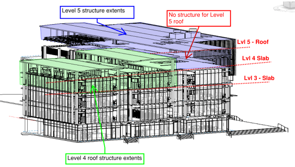
Task 1. UoW – Structural Steel Frame design on Levels 4 & 5. I was tasked to develop the concept designs for the entire level 4 and 5 structural steel roofs. In the initial stages, I had to scrutinise the architectural model in Revit as well as the architectural floor plans to produce some initial layouts for a frame. The aim was to create a frame layout that would correspond with the Architect’s floor plan but, also achieve continuity of load run-down through to the concrete frame to avoid load transfer. The level 4 roof was to be built off the level 3 slab, and the level 5 roof off the level 4 slab. You can see the extents of the steel frames for level 4 and 5 in RBG’s structural BIM model below (you can see that level 5 had no structural elements at this stage). My initial layouts were incorporated into the BIM model and the in-house draftsman created some hasty level 4 and 5 general arrangements (GA) for further design development.
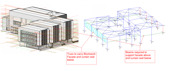
In order to simplify the analysis and design, I decided to consider level 4 & 5 separately. I used a software package called Microstran (I agree with Brad, much easier than STAAD) to complete the analysis for the indeterminate frame. The biggest challenge was ensuring that lateral stability was provided and that the frame included members to support the various architectural features (e.g. curtain walls and façade). I finally opted for horizontal and vertical bracing in order to provide lateral stability (loads eventually running back into structural slab). The image below shows my Microstran model for level 4 and the various structural elements that had to be included to support some of the architectural features.
 To create a working model, the nodes and members had to be modelled accurately in order to complete analysis. Deciding whether a connection was to be pinned or fixed was very challenging. The process helped me understand how the overall structure and individual members were behaving (e.g. tension only members, what the different connection types would be and what forces could be transferred). To simulate the interaction between the frames on level 4 and 5, I modelled the connection as pin supports.
Once the associate engineer was satisfied that my model was stable, I then had to calculate the actions and create the design load combinations for the model (22 in total). This included the calculation of wind actions using Australian Standard (AS) 1170.2.2011: Wind Actions. The process was similar to EC; you work out the design pressure and your net pressure coefficients to get a KPa value (extract from my calculations below).
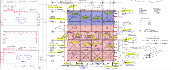
After calculating the actions on the structure, I then assigned section classifications to each member in the model. I started by considering the primary rafter and modelled it as a SS beam to get a ballpark BM. With the primary member assigned, I worked through the structure and reduced the section geometry as I went. I had to go back and change some of the sections, as RBG will typically use particular sections for different purposes (e.g. CHS/SHS for struts and EA for ties). With more experience, this process would be more intuitive. The image below shows my final model for level 4, the different section classifications are indicated by different colours (left image). The image on the right is my final analysis and shows the BM envelope for all load combinations. I used the results to complete strength and serviceability checks on the sections I had chosen. Australia didn’t completely copy the English on this one, they have the RED BOOK for their steel section properties and capacities. Deflections and bending capacities were satisfactory (Span/500 was used to be conservative). I did have to incorporate some fly bracing (restraints) to reduce the effective length of the main rafters; to prevent buckling in the wind suction case.

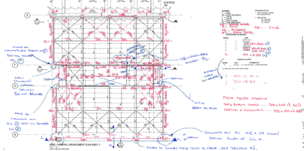
RBG subcontract the final production of structural drawings to RAMTECH software solutions in India. Therefore, I had to produce some marked up GAs and elevations to communicate my design output for final drafting (see examples of my work below). The final drawings will be issued to the competing contractors, via the client, to assist with pricing the job for tender submissions.

Task 2. BMDH – Precast concrete façade inspections. I was also tasked with overseeing the final approval and inspection of some pre-cast concrete façade panels on the BMDH. The panels are essentially SS slabs on the outside of the building. They are supported at the top of the panel by a corbel that sits on the structural slab and is pinned by a dowel connection (see image below).
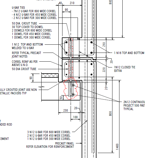
The design had already been completed for the panels and I just needed to check the details during my inspection. However, I wanted to understand how the panels were behaving and did some simple analysis to identify where the critical points for inspection were. I deducted that the shear load in the dowel connections was critical and that the critical BM would be in the corner of the panel (FBD and quick analysis below). The wind action would also create biaxial bending (so vertical and horizontal reo required in panel).


The panels were being constructed by Hanson in their factory just outside Sydney. The Architect (Jacobs) and Contractor (AW Edwards) were also present during the inspection. The reinforcement was satisfactory; however, honeycombing was identified in some of the corbels, which reduced the cover and durability of the section. Hanson will now provide a product specification and methodology for patching in those areas.


Pre-stressed concrete canopy analysis and design verification. Destined to fail?!
My current task on site is the construction of four pre-stressed concrete canopies (locations in fig 1 below). At first I wasn’t expecting any engineering challenges; however, they have offered some valuable experience in first principle analysis, contracts, building techniques and safety in design (AUS equivalent of CDM).

Figure 1 – Location of four pre-stressed concrete canopies to be constructed.
The Canopy Structure and load path.
All canopies will be constructed in-situ and off formwork to a class 2 finish as specified by the Architect. The canopy slab is reinforced concrete with post tensioning tendons running between the columns. At the edge of each slab, on the tip of the cantilever, is an architectural trim that weighs an additional 1.5 tons. The columns are also reinforced concrete and transfer the loads through to a reinforced concrete pad footing. The loads are then transferred into the ground using helical/screw piles which have already been constructed. A plan view of Canopy 01 can be seen in figure 2 and a typical section through the canopy can be seen in figure 3.

Figure 2 – Plan view of Canopy 01.

Figure 3 – Typical section through the pre-stressed canopy. Radial line to be used for analysis.
Contractual Arrangements
The Roundhouse project and the Science and Engineering Building (SEB) Project have been executed under two different contracts. The SEB has been procured under a Design and Construct (D&C) contract, whereas the Roundhouse is part of a two stage Managing Contractor (MC) contract. The first stage of this contract was for the Roundhouse works and the second stage is for the external landscaping, referred to as the Public Domain works. Whilst the MC contract means that the principle has final authority on all design decisions and appointments of subcontractors, the second stage is still in the Early Contractor Involvement (ECI) stage, where MPX are essentially coordinating the design process, without carrying any liability for the final design. Stage 1 of the contract is essentially a traditional construct only, where the 100% detailed design was provided by the principle and the principal’s consultants. Therefore, MPX have no liability for the design and only review the drawings on a buildability basis. However, when there are concerns over the design, a request for information (RFI) can be raised to seek further approval of design.
The Issues
1. The structural consultant’s scope included the design of all elements apart from the screw piles, which were specified by the groundworks subcontractor’s (FCC) specialist consultant; Helcon Contracting Australia.
2. Concerns over the working loads created by the cantilevered slab on the foundation piles, including the impact of the stainless steel trims. The stainless steel trims were an architectural design variation and were not included in the structural consultant’s original calculations. The working loads specified by the structural consultant were 350 KN (SP2 – Compression pile) and 175KN (SP3 Tension pile) as shown in figure 4.
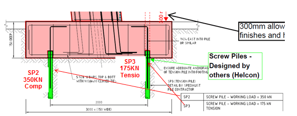
Figure 4 – Detailed section through canopy footing. 2 screw piles are designed to deal with moment created by the cantilever. Working loads specified by structural consultant shown.
3. No pile design calculations were received by MPX from Helcon for the screw piles. Helcon only specified the section geometry. Torque and depth readings were submitted as part of the inspection and testing plan (ITP) during construction, which Helcon used to produce a certificate of compliance. My primary concern was the depth of the screw piles. The site record shows that the depths were taken from ground level; however, the actual length of pile in the ground would be much less as illustrated in figure 4. After the footings have been constructed, the actual length of pile in the ground would be reduced to 3.35 metres.
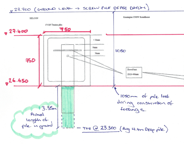
Figure 5 – RLs (AHD) for footing and pile depths. Screw pile records were taken from existing ground level.
Analysis (simple radial slice through the structure).
My aim was to ultimately determine if the structure would stand up! In order to do so, I did the following:
1. Analysis of the cantilever slab in order to calculate the maximum possible moment and axial load transmitted into the columns. The working loads in the screw piles could then be determined with a simple FBD.
2. Complete design verification of the screw piles by calculating the ultimate capacity and also determine theoretical ultimate capacity based on torque readings taken on site.
3. Compare working load vs ultimate capacity.
In order to determine the maximum moment created by the cantilever slab, I assumed that all loads from the slab are transferred to a column strip that will be modelled as a concrete beam. The middle column will be the worst case for Canopy 1 as shown in figure 6; the orange area indicates the section of slab that will be transferred to the beam strip highlighted in pink.

Figure 6 – Area of slab assumed to be transferred to notional beam highlighted in pink.
Design UDL = 83 KN/m (plus 6 KN PL at end of cantilever)
Cantilever slab analysis determined that the axial load in the column is 500 KN and the balance of the bending moment transferred to head of column is 487 KNm. The stainless steel trim only creates 5 percent of the total moment created (24KNm) and therefore its additional load is not overly critical.
Therefore:
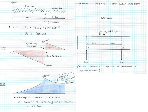
Figure 7 – Cantilever slab analysis and FBD for base of footing.
∑M @ A = 0 Therefore, (500 x 1) – 487 + (Tp x 2) = 0
SP3 = 6.5 KN (Compression)
∑V = 0 Therefore, Cp + 6.5 – 500
SP2 = 494 KN (Compression) > 350 KN
! WORKING LOADS GREATER THAN SPECIFIED BY STRUCTURAL CONSULTANT!
Screw pile estimate of ultimate design capacity.
The screw piles installed for the concrete canopy footings only have a single helix of 350 mm in diameter and the shaft diameter is 114 mm. An illustration of the screw piles used for the canopy footings can be seen in figure 8 below.

Figure 8 – Geometry of screw pile used for footings. Single helix at the toe of the pile.
Compression capacity (SP2 piles)
The ultimate compression capacities of the piles were obtained using effective stress analysis as follows:
Qult = AH (σv’ x Nq + 0.5 x y’ x B x Ny’)
where:
AH = Surface area of helical base plate
σv’ = vertical effective stress at the level of the helix/toe (D) = y’ x Depth.
Nq and Ny = bearing capacity factors
B = diameter of helical plate
y’ = effective unit weight of soil
GWL below toe of pile, so pore pressures assumed to be zero.
Therefore,
Nq (VD Sand φ’ = 37) = 40
Ny = 62
AH = π x r² = 96200 mm² (0.096 m²)
σv’ = σ – u = (16 x 0.65) + (17 x 1) + (18 x 1) + (19 x 0.7) – u (o – no pore pressure) = 57.7 KN/m²
B = 0.35 m
y’ = 19 KN/m³
Qult = 0.096 ((58 x 40) + (0.5 x 19 x 0.35 x 62))
= 0.096 (2320 + 206)
= 242 KN in compression < 350 KN Specified & < 494 KN working load calculated (FAIL)
If, full depth pile from ground level as recorded in ITP i.e. pile is 4.5 m in full length.
σv’ = 76 KN/m²
then Q ult = 0.096 (3040 +206)
= 311 KN < 350 KN Specified 494 KN working load calculated (Still FAIL)
(Shaft resistance ignored as it contributes very little to the ultimate capacity).
Screw pile capacity based on torque readings
The torque readings taken during installation appear to be the only basis for confirming the design capacity of the screw piles. In short, capacity of pile based on torque reading is:
Qult = kt x T (Kt = Torque correlation factor)
= 18 X 20000 = 360 KN > 350 KN specified working load (OK)
< 494 KN working loads calculated (FAIL)
Summary
Maximum working load from radial slice analysis 494 KN (Compression)
Maximum working load specified by Structural Engineer 350 KN (Compression)
Maximum Compression Capacity of screw pile 311 KN (FAIL)
Compression capacity of pile based on torque 360 KN (FAIL)
Questions for the group
By modelling the structure as a simple slice on a radial line, my calculations suggest that the structure will fail!
My working loads greatly exceed the structural engineer’s estimates and the capacities calculated. I think that my analysis is the extreme upper bound model and loads could be overestimated? Am I missing something on this one?
Although the capacities of the pile based on torque and effective stress analysis are relatively close, by only assuming that the top of the helix is providing resistance, I suspect that my calculation of screw pile capacity is underestimated.
Moment Capacity For Circular Pile Section! Any Thoughts?
During a routine inspection of pile caps prior to concrete this morning, I identified that one of the piles was offset by 216mm! At first glance it didn’t look that significant. However, the drawings highlighted a tolerance in plan of 75mm and the Mecc in the pile design was 206Knm! A Non-Conformance Report (NCR) was issued to the groundworks subcontractor immediately and they were told to assess the impact.
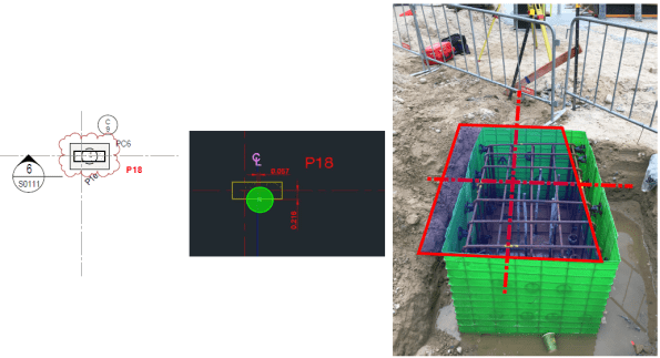
Markup used to highlight problem for NCR. Dashed line shows actual C/L for column.
This would have an impact on the pile and the pile caps, which were procured via 2 different subcontract packages with 2 different design consultants. Because of this I knew that a resolution wasn’t coming anytime soon and I wanted to complete some of my own checks.
I could see 2 potential problems with this:
- You can see in the image above that the steel fixers have just plonked the reo cage for the cap directly over the pile, which leaves the column off centre on the pile cap. This would create some bending stress in the pile cap and tension stresses may develop in the concrete = BAD. (Did quick P/A – M/Z = -0.5 N/mm2! Not sure how significant that is?)
- If the pile cap is moved back into the correct position (outlined in red above); then the pile is offset = Moment created in pile head due to eccentricity.
The images below show a section through the problem and some rough calculations. In summary, the moment created by the eccentricity is 594Knm and a quick strut and tie model identified a tensile force of 634KN in the top of the cap, therefore, Ast required = 1585 mm2. The current N16 @250 E.W.T.B was insufficient and I think additional steel ties will be required in the top of the pile cap. Not a showstopper.


I THEN HIT A WALL!! HOW DO YOU CALCULATE THE MOMENT CAPACITY OF A CIRCULAR SECTION?
I’m sure the answer is glaringly obvious, but I couldn’t get my head around it. As an alternative I transformed the circular section into a square section and reduced its capacity by 10%.
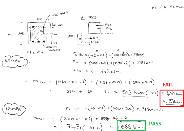
Whilst checking the ITPs for the CFA piles, I also identified that the concrete strength used was 65 Mpa, despite the design and construction drawings only calling for 40 Mpa. Nobody on site can recall why 65Mpa mix was used, but my calculations show that this apparent mistake could actually have increased the piles flexural capacity enough to resolve this issue!
Below are my calculations for Mmax. If anyone can provide a solution for a circular section it would be much appreciated.
SLOPE STABILITY ASSESSMENT FOR TOWER CRANE ERECTION
Apologies for the long winded explanation that follows this intro! In summary, I have a slope stability problem and if anybody could provide solutions in addition to the ones I’ve suggested below that would be great. My solution also requires fill that I assume would need to be compacted? Has anyone done any work on compacted effort required in coarse grain soils? Any other thoughts appreciated also.
My primary responsibility at the moment is managing the construction of the tower crane for the SEB site. This has principally involved managing and coordinating contractors to ensure that all enabling activity is completed for this Saturday (1 July 17).
The tower crane will be constructed in sections through the use of another 300 tonne mobile crane. Figure 1 below shows the site layout for the tower crane construction. The main boom arm will be constructed on the road before being lifted into position. The red highlighted area shows the extents of a slope which separates the two construction zones (North and South) and the blue highlights the outrigger pad areas.

Figure 1 – Site layout for tower crane construction.
The crane company are required to complete a lift study for the exact location of the crane in order to accurately calculate their maximum boom radius and resulting loads that will be transferred into the ground via the outriggers. During planning the location as shown in figure 1 was agreed and a lift study was completed by the crane subcontractor. The resulting loads were 90 tonnes through each outrigger, which with pads of 2.5 x 2.5 m creates an operating stress of 144Kpa (I conducted a quick bearing capacity check for the loose sand layer to 2.5m which produced a stress at which failure occurs of 360kpa. No FOS!). One of our contract clauses requires MPX to complete DCP testing for any activity requiring outriggers. It was only once the positions of the outriggers were placed on the ground that I realised that we could have a possible slope stability issue. The image below shows the profile of the slope and the position of the mobile crane outriggers.
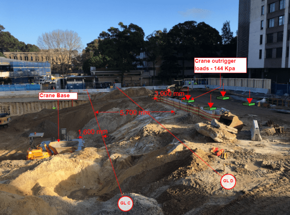
Figure 2 – Current slope profile and position of 300T Mobile crane
The proximity of the outrigger pads to the crest of the slope was a concern. The geotechnical engineer had also specified batters of 2:1 (H:V) throughout. The slope was clearly not 2H:1V. It was almost 1:1 with reduced level (RL) at the top of crane base of 24.000m AHD and a RL of 29.000m AHD at the top of the slope.
Transferring risk is the Multiplex way and the decision was made to get the Geo consultant (Coffey) to inspect and approve a solution. They will be visiting site tomorrow!
Smelling an opportunity to conduct some much-loved geo analysis, I immediately leapt into action and retrieved my John Moran Slope Stability notes in order to see if the current slope would be safe. About an hour or so later I realised that I was stumped. I understood the Bishop’s method of slices, but I couldn’t see how to model the surcharge load created by the crane outriggers (any advice would be appreciated).
I eventually decided to go back to first principles and use the equilibrium equation ∑M = 0. The idea was to take moments (resisting moments divided by disturbing moments) about the origin of the slope to determine a factor of safety (FOS).
Assumptions:
- No GEO reduction in soil parameters. All ϕ’ values etc taken from Coffey’s GDR.
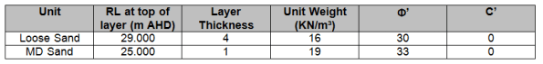
- GWL is at measured mean levels (22.6m AHD) and therefore no pore pressures considered in calculations.
- Failure would be a circular slope within the loose sand layer (this was also based on the fact that the pile cap would provide toe stability and additional anti-clockwise moments about the origin).
- No consideration made in hand calculations for DC1 or DC2 i.e. factoring the soil parameters of loads.
Figure 3 below shows my hand calculations for the existing site conditions. The FOS was 0.91; so a risk that the slope would fail if not modified.
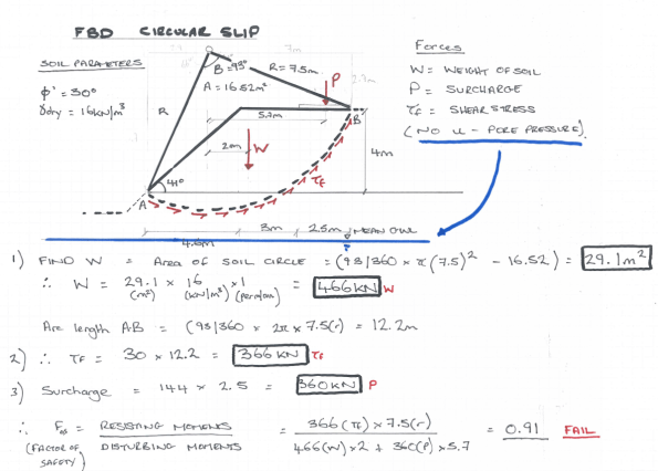
Figure 3 – Slope stability hand calculations for current soil profile.
When looking at solutions to this problem I could see 2 possible solutions:
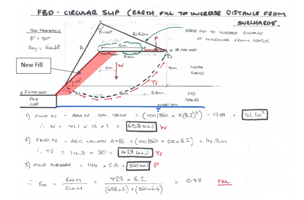
- Place additional fill on the slope to increase the distance of the surcharge from the crest to 5 metres.
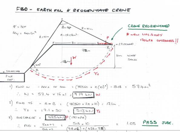
- As above, but also re-orientating the crane to further increase the distance of surcharge to the crest (This required a new crane lift study as boom ranges would increase; this was completed for contingency and outrigger stresses increased from 144Kpa to a maximum of 170Kpa).
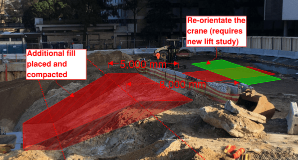
Figure 4 – Potential solutions on a mark-up.
Solution 1 Calculations – Build up slope with fill only (FAIL).
Solution 2 Calculations – Build up slope with fill and re-orientate the crane (PASS –JUST).
My results showed that the crane would need to be re-orientated and additional fill would need to be placed to increase the distance between the surcharge load and the crest of the slope. Mindful of the fact that my hand calculations may not be entirely accurate, I also checked on GEO5. Results are shown below, generating similar results for the current profile but passing on both solutions (only just passing for solution 2).

Based on these calculations I would suggest that the distance from the crest of the slope to the outriggers needs to be increased by placing some additional fill and by re-orientating the crane. The lifting will also need to be monitored very closely to ensure that loading conditions don’t increase (i.e. lifting study boom ranges are not exceeded) and the outrigger plates are the correct sizes. It will be interesting to see what the Geotechnical engineer comes up with tomorrow.
Contamination Crisis – UNSW
G’day gents (had to do it). Australia has experienced a record breaking 23 days of continuous rain, so I have managed to maintain my pasty complexion. Quick orientation – My site is at the University of New South Wales where there are effectively three separate projects. The main event is the Science and Engineering Building (SEB). The substructure consists of a contiguous pile wall (CFA piling), followed by a bottom-up concrete sub/superstructure. The Roundhouse is a refurbishment (including significant structural steel strengthening) of the University’s precious student union. It’s the oldest building on campus and there is a big push to complete before Christmas for obvious reasons. The Hilmer building is a M&E services fit out project.

Contract arrangements.
Shock – none of the projects has a formal contract. A letter of intent was issued only last week to continue with works on the Roundhouse and the SEB contract is still being negotiated (current works including piling mattress form part of the early works letter of intent). Multiplex are pushing for a Design and Construct (D&B) contract, but the client wants more influence via a managing contractor contract. In addition, the SEB still doesn’t have Development Approval (DA) from the council and the delivery of the piling rig has been pushed to the right by another 2 weeks as a result.
Contamination Issues.
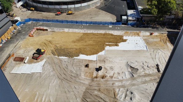
The Geotechnical Engineer found no evidence of ground contamination during his GI. However, whilst the SEB site was being excavated to formation level in preparation for construction of a piling mattress, bonded asbestos was identified on site (believed to be old formwork panels from previous construction that were dumped in an excavation!).
There were 2 potential remedies. First was to employ a hygienist to sift through all excavated material and inspect each load as it left site. Or alternatively just remove the first 1.5m from across the entire site and classify the whole lot as General Solid Waste Asbestos (GSWA). Surprisingly, this was only $2/tonne more than normal GSW and therefore a mere $26,000 of additional cost. The total effort was 13, 000 tonnes of waste material that required approximately 600 “truck and dogs” (Aussie slang for a truck with a large 12 tonne skip on the back). I was involved in producing high risk workshops and removal control plans for the site. Clearance certificates were issued for the site and piling mattress construction has begun.
On the roundhouse, the existing steel structure was covered in lead paint (for fire proofing I assume). This was obviously identified and considered in the programme, but the length of such a process was hugely underestimated. The programme is now 4 weeks behind and only 30-40% of the paint has been removed. The first option considered was to sand blast it off. However, this idea did not survive very long due to the clean-up effort required and the difficulty of containing air particles. The second option proved mildly successful and involved soaking the lead with a gel before blasting off the lead with dry ice pellets in a spray gun. See dry ice pellets and gun operator below.
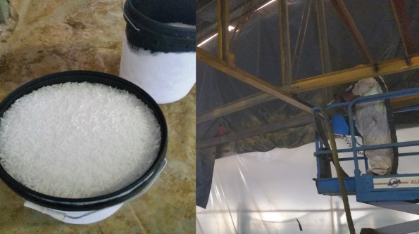
However, although successful, it is a painfully slow process, even after reinforcements arrived with additional guns. Yesterday the subcontractor switched to a soaked paper peel that is applied overnight before being peeled off with ease, bringing the lead with it, the next morning (very effective). Unfortunately, whilst everyone was high-fiving each other, some of the solution dropped onto the leg of one of the workers and it burnt straight through his PPE! All work has been stopped until a new Safe Work Method Statement (SWMS) is produced by the subcontractor and reviewed by MPX. That is tomorrow’s problem…….
