Archive
Integral Bridge Design
Now firmly settled into Phase 3, I thought it was about time I provided an update of my most recent ponderings.
I am working for Tony Gee and Partners on a new link road near Wigan. The A49 Goose Green to Westwood Park Link Road scheme comprises a new 2.3km highway to relieve congestion and provide future access to a new development – Westwood Park. The scheme consists of a new dual two lane carriageway with new non-motorised user routes, four new road bridges, two new footbridges and culvert repair works. Two new roundabouts will be built as part of the scheme to provide access and distribution into the future development of Westwood Park. The scheme provides design opportunities across highways, structures and geotechnical disciplines.
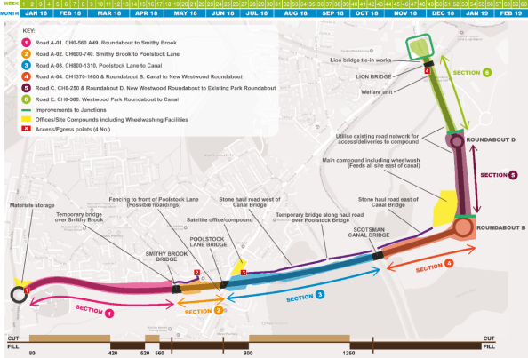
Proposed A49 Route with Route Sections & Structures
Roles – One of my current responsibilities is for the developed design of Scotsman Canal Bridge. This was tendered as an integral bridge under the ER’s. The design consisted of 8No. 1.6m deep W12, 32.3m long, precast pre-stressed concrete bridge beams supporting a 250mm thick reinforced concrete bridge deck. The bridge has a 13.7° skew. The superstructure is made integral with reinforced concrete abutments supported on reinforced earth embankments atop a 7m wide zone ground improvement.
Integral bridge design solutions (designed without any expansion joints between spans and abutments) offer a host of benefits from increased durability, reduced maintenance and lifecycle costs. However, they can pose the designer several issues to consider from the moment connect between beam and deck to the geotechnical issues of increased earth pressures and deformation behind the abutments. At the moment these are problems for future Al to overcome – so wait out for further blog posts!
A calc or two – Given the rushed nature of tenders, one of my initial tasks has been to verify the tender design for various aspects. These have included;
- Verifying the abutment pad pressures – The ground improvement works that the proposed abutments are to be sited on have a maximum uniform bearing pressure of 170KN. Assuming the carriageway dimensions in the tender and a precast manufacturer of the W12 beams a permanent load take down was achieved. The tendered ER’s stated an SV 196 variable loading requirement. From BS EN 1991-2 a Group 5 loading regime was assumed with LM1 and LM3. In the same vein as Ex Bridge, the notional lanes and load models were calculated to attain a variable load adequate for the purposes of this rough pressure check. My initial verification checks noted;
122KN (permanent) + 64KN (Variable) ≥ 170KN ∴ Not Okay
However, it is deemed that values used for verification are very conservative and so this could be satisfied later in developed design.
- Verifying Edge Beam Arrangements – As designers there is a need to design for the execution phase. One of my tasks has been to verify various edge beam arrangements for the contractor to choose as a desired install arrangement. This has involved creating beam arrangements around; beam, parapet and deck elements. From here the permanent load of the system is calculated and then the beam arrangements are checked for global stability / overturning moments allowing for wind and pedestrian effects. A summary sheet is then provided to the contractor in order to allow an informed choice of install arrangement.
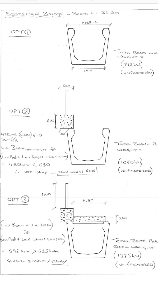
Sketch Summary sheet
I have quickly realised that in the design office communication is as important a skill as on site. Communicating assumptions and/or queries early makes for a smooth and productive design phase. However, this information also needs to be succinct and relevant to the recipient.
I hope to provide some details of the developed design in the coming months as I get to grips with LUSAS!
Al
Beams with a twist
I would appreciated peoples thoughts on the below issue I have encountered on site.
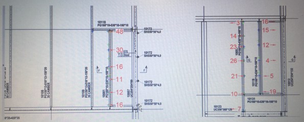
ISSUE: The steel frame erection is generally progressing well on site with approximately 90% of the steel work now erected. Unfortunately a recent site inspection highlighted that some of the secondary steel beams to level 02 had developed a twist in the member (see below). Level 03 above is a cantilevered deck which is currently temporarily supported through diagonal bracing.


The tolerances for the steel work on the project are laid down in the Structural Steel work Specification developed by Ramboll. These are in addition to the requirements of the National Structural Steel work Specification (NSSS). However, establishing the tolerances for the twist has proved more difficult than first thought. The steel contractor is currently attempting to determine a root sum squared answer from the fabrication and erection tolerances. In the meantime the visual distortion has been enough to instigate further investigation.
An as-built survey conducted by the steel work contractor confirmed the following ‘out of tolerances’ for three of the beams highlighted on site.
OPTIONS: The two options as I see it are to either leave it as it is, or to release the members and conduct remedial works as necessary. In both situations an evaluation of the significance of the twist is required to be made.
- Assess the structural significance of the twist. If not significant then do nothing and except the visual impact.
- Assess the structural significance of the twist. If not significant then do nothing, but weld a plate to the bottom flange in order to mitigate the visual impact.
- Assess the structural significance of the twist. If significant, release the connection. Relocate fin plate on primary beam to accommodate altered position of the secondary.
We are currently finding that, possibly due to the consequences, neither the structural engineers nor the steel subcontractor are willing to comment on the structural implications of the twist to the members and subsequently commit to a strategy moving forward. We are due to remove the temporary bracing in the near future. It is hoped that this along with the erection of the cladding will counteract the twist, however it is unlikely to counter it to the extent required.
It would be interesting to hear the thoughts of others with regard to the issue and potential remedial options? I would have thought that this issue must have been encountered previously through the experience of others? Any feedback is appreciated. Cheers, Al.
S2 Kings Cross – Orientation
I’m now several weeks into my Phase 2 placement with Carillion plc and it’s time to break my blog cherry. This post will hopefully serve to provide a quick overview of the project and company with an emphasis on pictures rather than words!
Site Orientation
The King’s Cross estate is owned by, and being developed by the King’s Cross Central Limited Partnership. One of the largest redevelopments in London, the 67-acre site has a rich history and a unique setting. What was an underused industrial area is being transformed into a new part of the city with homes, shops, offices, galleries, bars, restaurants, schools, and a university.
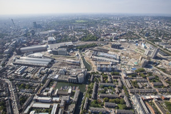
Kings Cross Development Area (looking West) circa 2008
The S2 site is one of seven sites that Carillion currently have within the Kings Cross Development Area. Two other contractors (Kier Group and BAM Construct) also operate sites in the development.

Kings Cross Development Site Plan (Purple-Carillion, Red-Kier, Green-BAM)
S2 project Outline
Kings Cross S2 is a new £78 million commercial office development comprising; eleven storeys of grade A commercial office development, over; retail, lobby and further office space at ground floor level, over; deep single storey basement housing plant tenant cycle storage and changing facilities and welfare. Further plant is located at levels 10 and 12 with a tenant roof terrace located at level 11. The tenant is Google UK who have signed a 17 year lease on the development. As the initial tenants numerous aspects of the build conform to their specific requirements, including double height floor spaces to various areas and open lobby spaces
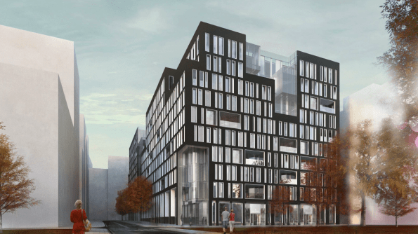
Architects image of completed S2
The building frame consists of a reinforced concrete basement and ground floor, with steel frame superstructure and composite floor system. Stability is provided via a central reinforced concrete core, which is formed around passenger lifts and stairs. The cladding system is a 1.5m unitised system, with a stone faced façade. Within the superstructure of S2 there are a number of cantilever floors and setbacks. On the south-eastern corner there is a large cantilever at fourth floor level.
The substructure consists of reinforced concrete basement and ground floor with rotary bored pile foundations into London clay. Contiguous piled walls on each basement wall provide temporary retention and permanent vertical support to columns.
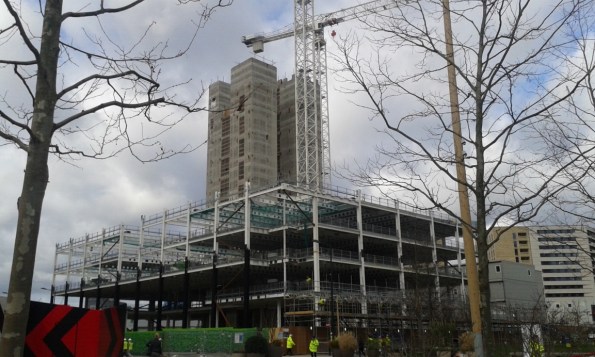
S2 Progress – March 2017
Contract Information
The main contract between Carillion plc and King’s Cross Central Limited Partnership is a JCT (2011) Design and Build contract with Employers Amendments. The price and payment structure of the contract is based on a lump sum with interim stage payments. The contract seems to work well on the S2 project with its provisions for collaborative working and sustainability meaning there is a real team ethos between client and contractor with a shared effort when issues are encountered. The current completion date for the contract is March 2017.
A two stage tender process was implemented for this contract. Stage one was a competitive tender aspect between Carillion and BAM, both of whom were selected off the clients selected delivery team members list. Carillion was successful at stage one and so moved forward to stage two which was a negotiated element directly between the client (Argent) and the contractor (Carillion).
Roles & Responsibilities
My current role is as the Construction Supervisor for the superstructure on the S2 project. I work directly to the Package Manager (Construction Manager) for the superstructure/substructure. Given my parameters I liaise with the other Package Managers (Fit Out, Envelope and M&E) in order to expose myself to as many activities and issues as possible. My initial time has seen my attention focused on health and safety matters and quality concerning the steel erection and composite floor construction. This period has proved challenging at times with a steep learning curve endured with regards to the project and company processes, however, this has allowed me to immerse myself in the project and understand how the project it being run.
Summary
The S2 project seems an exciting project to be involved with. I feel the timing of the attachment has been well situated in terms of the project programme with a vast amount of activity currently being witnessed with numerous trades all working on site. As with probably all students my concern at this early stage is that I will be able to meet all the ICE Attributes in the time available.
I hope this post has been partly interesting in setting the scene. I will look to provide some site related engineering issues in the near future!
