Archive
Stadium Australia
Built for the Sydney Olympics, Stadium Australia originally looked like this…

After the Olympics, the stadium was expected to attract smaller crowds and so the terraces behind both goals were reduced. This modification has resulted in the present day configuration, see below.

The owners now want to make two further modifications. Now that the running track is redundant, the first alteration will see the seating brought much closer to the pitch, adding to the capacity and atmosphere. The second alteration will see the addition of a roof, see below.

Whilst both endeavors are intrusive, the alteration of the seating arrangement is the greater challenge. This is because the trusses which span over the length of the stadium were designed with a roof in mind – bonus.
The box and mid terrace which run the length of the pitch are cantilevered from the main structure. The lateral push / pull loads are transferred to the core via the floor plates. Without a balancing load, this would cause the core to deflect towards the pitch. To counter this, vertical post tensioning runs the full height of the core, on the wall furthest from the pitch, see below.
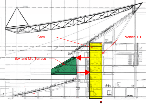
Key: green = terrace, yellow = core, bold red arrows = forces in floor plate, red line at back of core = PT.
To reconfigure the seating, the box and mid terrace will need to be demolished. The requirement therefore is to identify a methodology which allows the removal of the terrace without causing an unacceptable imbalance with the post tensioning.
My first intention is to track down the original construction methodology. Has anyone else been exposed to the modification of PT structures during their Phase 3? Suggestions on a post card please…
Agora Tower, Taipei, Taiwan
Check out this building!

http://en.prnasia.com/story/126403-0.shtml
http://www.designbuild-network.com/projects/agora-tower-taipei/
http://www.designboom.com/architecture/vincent-callebaut-architectures-agora-tower-taipei-taiwan/
![]()
Calcs v Real World
Hambly’s Paradox…
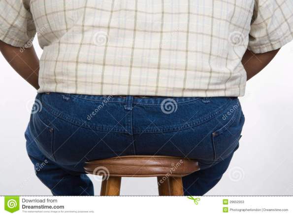
A man weighing 600N sits on a three-legged stool. The stool is symmetrical, the man sits in the centre of the seat. What basic force should each leg be designed for?
The same man now sits on a square stool with four legs, one at each corner, the stool and the loading are symmetrical. What force should each leg of the stool be designed for?
Concept Design…
A potential client, wanting a 7 storey building, is keen to discuss the advantages of ‘beneficial occupancy’. Interestingly the most valuable floors are levels 4 to 7 and as such, these are the priority. Having been approached with this request, RBG have offered a concept design which allows the contractor to programme the more valuable, upper levels ahead of the lower.
Step 1: Foundations and raft slab (black)…

Step 2: Jump the core (green)…
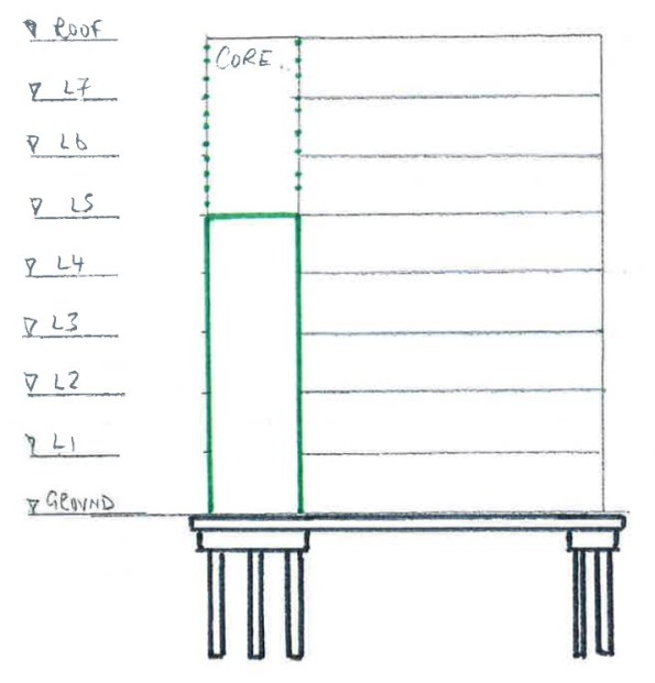
Step 3: Once the core has reached the required height (level 5), secure 15m prefabricated column (blue)…
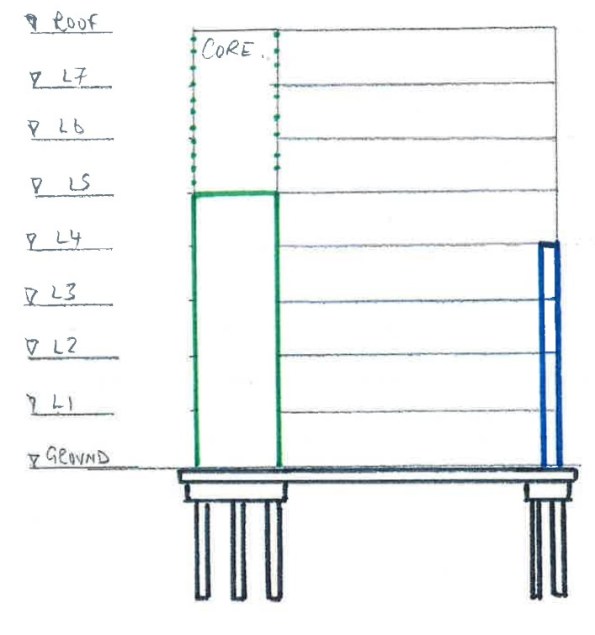
Step 4: Connect column to core at level 4 with prefabricated steel truss (red)…
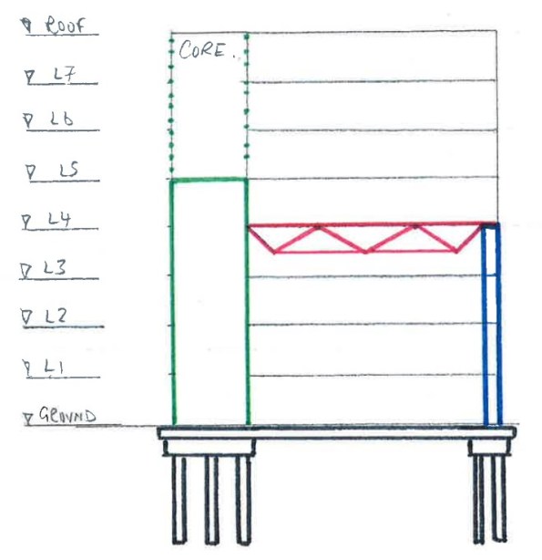
Step 5: Infill level 4 with precast slab and then progress concurrently through levels 5 to 7 and ground to level 3 using conventional falsework.
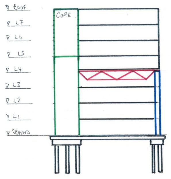
Step 6: Remove truss.
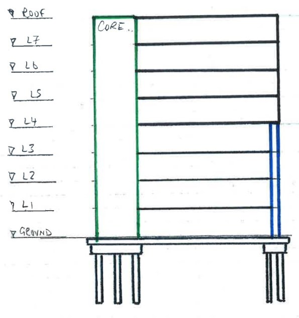
Whilst simple, this approach delivers the most valuable areas of the asset to the client earlier than conventional methods. It also negates the need for a ‘deep beam’ arrangement at level 4, maintaining level 3 headroom.
Unfortunately due to commercial sensitivities, I haven’t been allowed access to the cost benefit analysis of this approach. I have however been informed that whilst this approach costs more in materials, it delivers the most valuable areas of the asset sooner. The earlier delivery of levels 4 to 7 translates to an earlier profit for the client. This advance of profit offsets the inflated cost of materials.
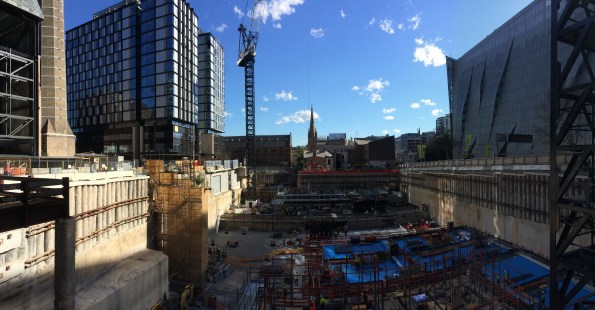
Site Inspection – in at the 1.4m deep end…
Anybody interested in what a site inspection of 1400mm deep, 5.5m cantilevering transfer beam designed to support 18 storeys looks like…
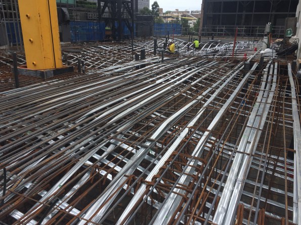
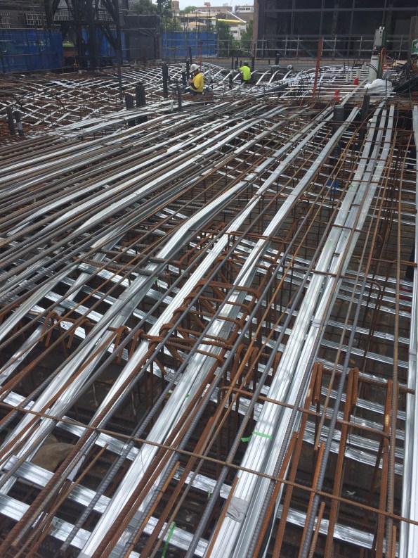
The PT is made up of 15.2mm diameter strands @ 300 centres. The cantilever supports 18 storeys with only 20mm deflection!
The construction of this was not simple. PT design is not in the structural engineer’s package, it is in the PT sub-contractor’s. Their original design saw almost half the amount of PT shown in the photo but and deflection of 38mm. By the time the design consultancy had highlighted the need to restrict deflection to 20mm, the PT had been assembled as per the original design. You can imagine the look on the contractor’s face when they were told more PT was needed. Due to congestion, the additional PT could not be added in a side-by-side arrangement, but by way of a second layer in the vertical plane. The contractor was not happy.
Phase 3: Week 1…
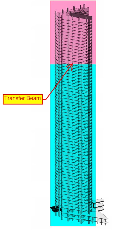
Since starting my Phase 3 attachment with Robert Bird Group last week I have been tasked with evaluating the current conceptual design of a 70 storey building. The main effort in this exercise was to see if the column layout could be revised to maximise floor space in the upper floors. An impression of the structure is in the figure below.

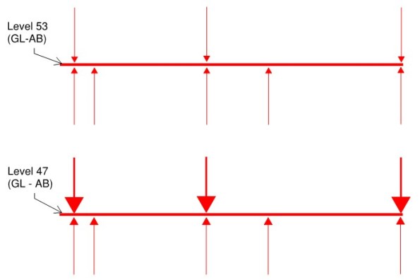
The current design sees a consistent column layout between Ground Floor and Level 53. Above Level 53, the layout changes to maximise floor space in the upper levels. My task was to evaluate whether the Level 53 transfer beams, would still work if they were moved to Level 47, without changing their geometry. The main consideration here is the additional load on the transfer beams caused by Levels 47 to 53. An illustration showing the approximate location of the transfer beams is in the figure below.
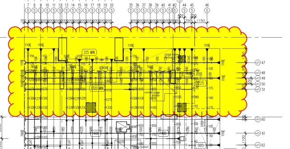
A plan of the structure is below. The two transfer beams have been highlighted.
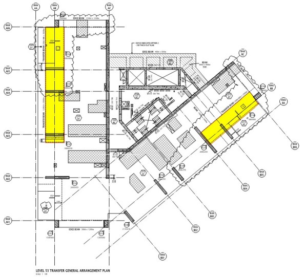
A simple sketch indicating the loads acting on one of the two beams is below. There are three columns acting as point loads on the beam, with five supports below the beam. Moving the beam lower in the structure simply changes the magnitude of the loads.
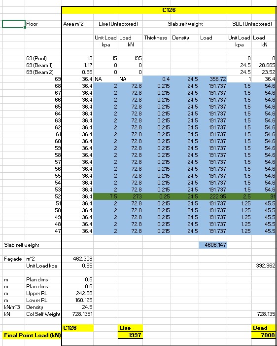
Once I understood the intent, I set about analysing the loads. I captured the loads acting on each floor and multiplied them by the area of that floor being supported by the columns in question. This allowed me to work out the magnitude of the point loads acting on the beam. An example of my load analysis for one of the columns is below.
I then added the UDL acting on the beam and checked to see if the beam could perform under the new design loads. This check was performed using a software package, commonly used by Robert Bird Group – ‘RAPT’. RAPT is not too dissimilar to STAAD Pro.
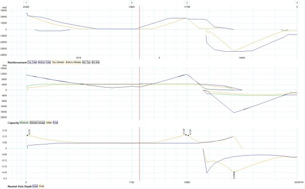
After running the check, I was able to confirm that the transfer beams could continue to perform as designed, without changing their geometry.
A relatively simple task, ideal for dusting off the Structural Analysis notes.
Duo – Central Park; key achievements…
Here are the key achievements of the Duo – Central Park project during my attachment so far. It hopefully provides Phase 1 students with an insight into the works packages Phase 2 can expose you to, when dealing with early structural works.
Feb – Apr 16. Although Multiplex had won the tender, several months past before a head contract was agreed. Site establishment and ‘early works’ commenced under a pre-contract budget. With the bulk excavation complete, the pre-contract budget allowed detailed excavation of footings to commence and the completion of general site establishment including temp services. In the meantime, project staff engaged in value engineering, rationalising, reviewing drawings and the identification of method statements based on anticipated buildability issues.


May – Jun 16. Contract signed. Detailed excavation continued and two tower cranes were installed. Whilst the majority of the project progressed through the pouring of footings, columns and SOG, my focus was on temp works in and around a heritage building. These temp works were required to provide structural stability to the heritage building before work on the new, adjacent structure could begin. These works involved underpinning and structural steel supports. I also had to identify methodologies for these key areas.


Jul 16. With the heritage building structural works complete, we progressed with piling and pile cap excavation.

Aug – Sep 16. With the piling out of the way, works in my AOR have progressed with the construction of four pile caps, a lift pit, PT slab removal and in-ground services.
Oct – Nov 16. My final couple of months have seen the completion of the following works in my AOR; SOG, columns from Basement to L1, a lift shaft and two suspended slabs. I have also completed the removal of HAZMAT (asbestos and lead dust) from the heritage building.
Early structural works provide exposure to a wide range of works packages. The individual can gain experience in ground investigation, piling, mass concrete, reinforced concrete, prestressed concrete, structural steel and more. The site experience goes beyond these packages to include high risk workshops, method statements, contract admin and stakeholder management to name but a few. In my experience, being a site engineer is like being a Tp Comd. I view my PM as my OC, my site manager as my SSM, my project engineer as my BGE / OpsO, my senior site supervisor as my staff sergeant, junior site supervisors as section commanders and the subcontractors as soldiers. To quote Gus, the only difference is ‘soldiers follow orders and require far less supervision’. Finally, for anyone thinking of working on a structure for their Phase 2 attachment, I think the course prepares you extremely well but I would have benefited from being more efficient at reading structural drawings. I have sent a drawing exercise to John Moran, not a bad place to start. Oh, and if you can, avoid scheduling reo like the plague!
Here’s a conundrum…
Did somebody order the spinning loading platforms???
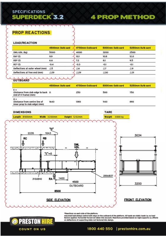
Preston Hire – ‘count on us’.
Contract Admin…
Having recently moved into the Contract Admin office for a couple of weeks I have had my eyes opened to a few things.

It appears there are several major subcontractors who have been working on site for the last few weeks without a contract. This issue has raised its head as we are currently processing many of the subbies’ progress claims and the figures aren’t adding up. The differing figures result from conflicting terms and condition. Unfortunately, as much of the works are underway, Multiplex has little leverage as the cost of replacing the subbies almost definitely outweigh the benefits. This means the subbies are in a very powerful position and are almost dictating their terms. It has also caused cash flow issues for some of the leaner companies as their anticipated millionaires’ weekend has been postponed. We are now exercising diplomacy and smoothing over the frictions, whilst also attempting to negotiate reasonable terms and conditions in order to finalise the contracts.
The contracts in question were the responsibility of an administrator who recently left without closing them out. Signed off, switched off…
Whilst on the subject of contracts, below is a link which may be of use to anyone else about to enter the CA world…
Modification of post tensioned concrete: update…
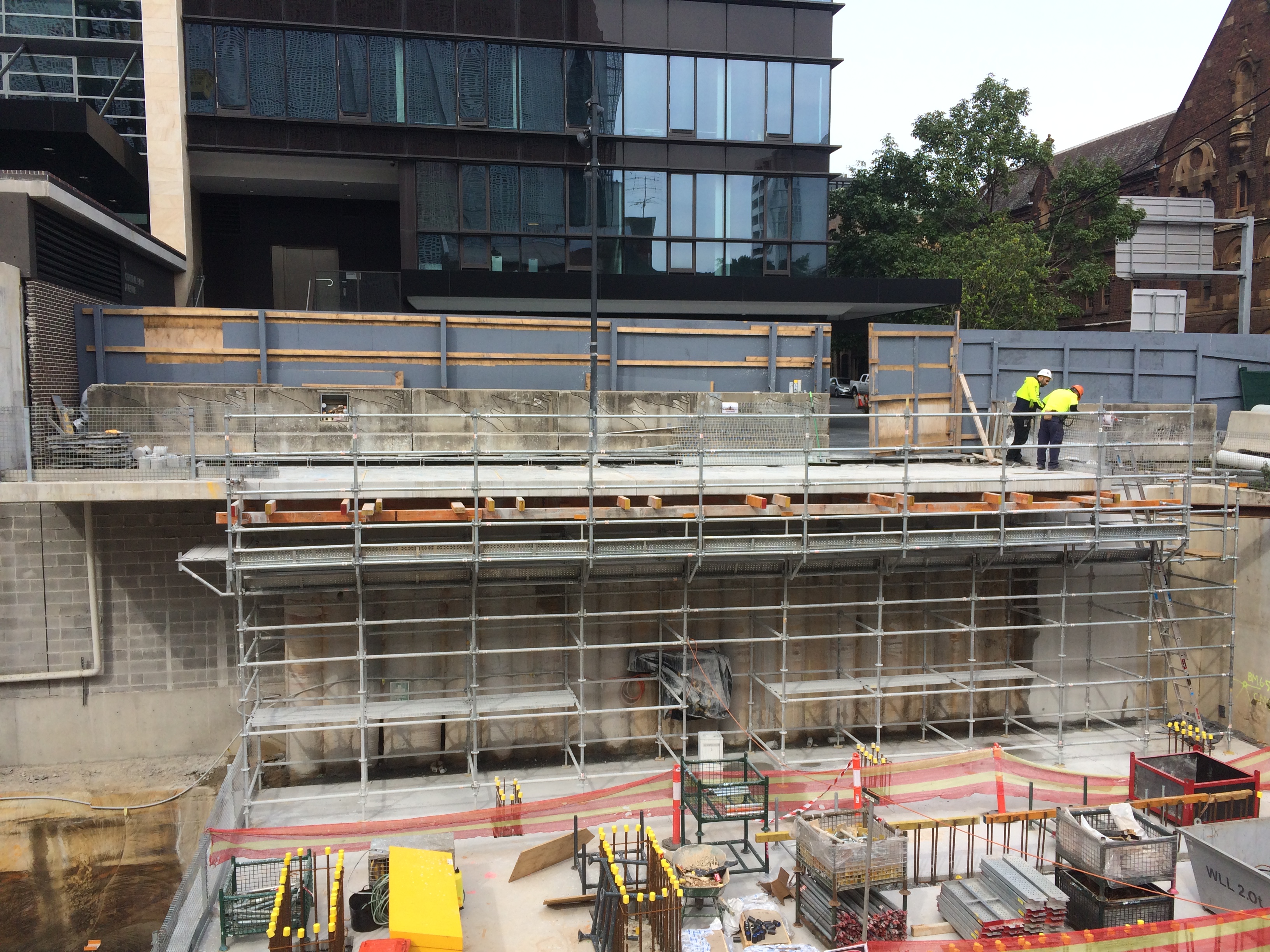
In my last blog I explained how I was planning the modification of an existing post tensioned slab, here is a quick reminder…
For unknown reasons the ground floor slab of an adjacent building cantilevered into our site by approx 2m. As we are building a bottom-up 4 level basement, this intrusion obstructed progress.
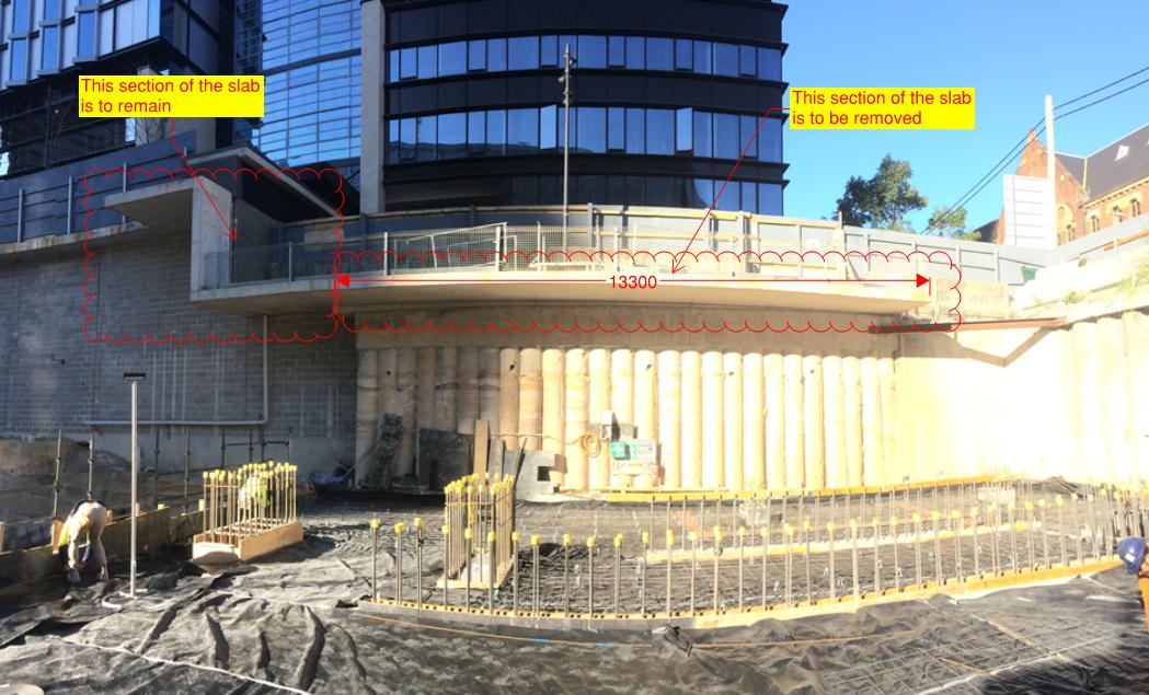
Step 1: In order to remove the offending section (2m x 14m, 250mm thk), we first analysed the likely effect on the remaining slab. This was anticipated to be between 2 and 5mm – acceptable. Step 2: We constructed falsework to the underside of the section being removed to allow the section to be temporarily supported between being cut and lifted out. This falsework also provided access for the crane crew and edge protection during the cutting process.
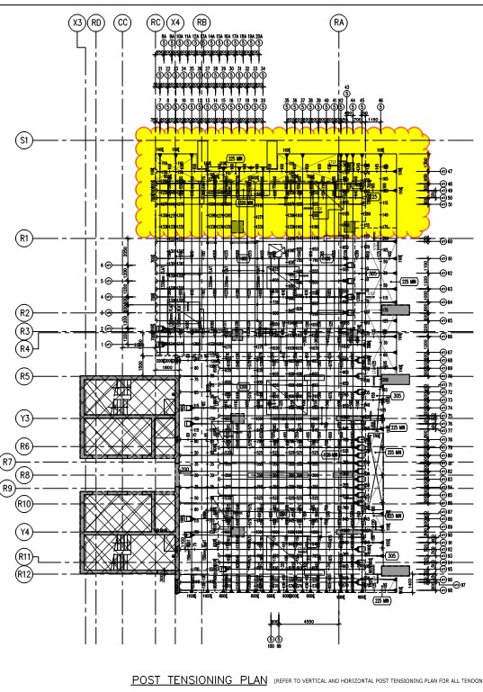
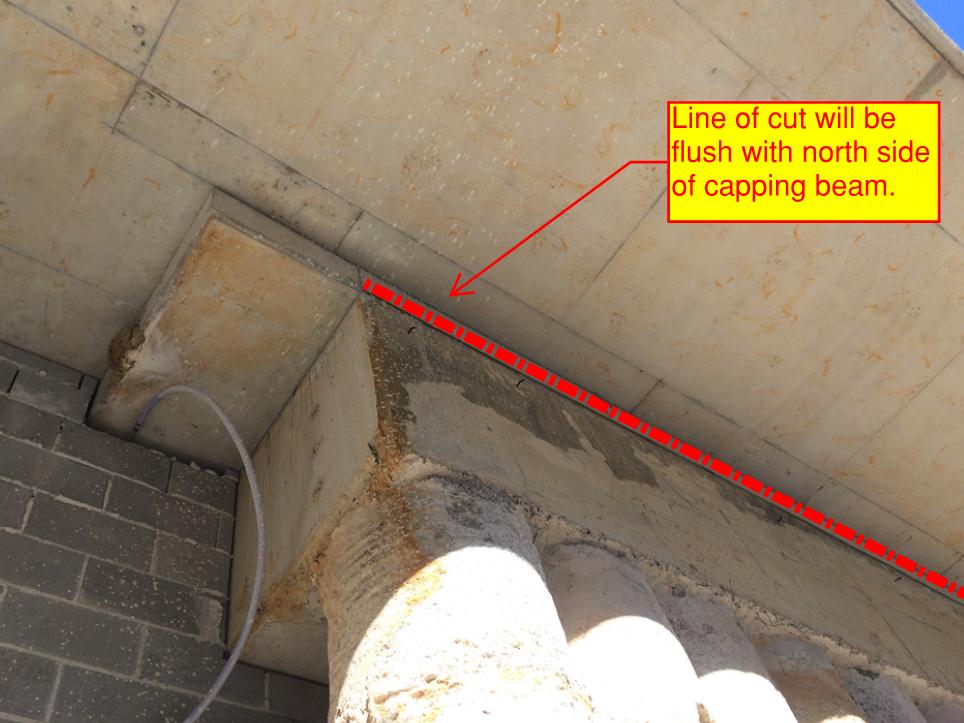
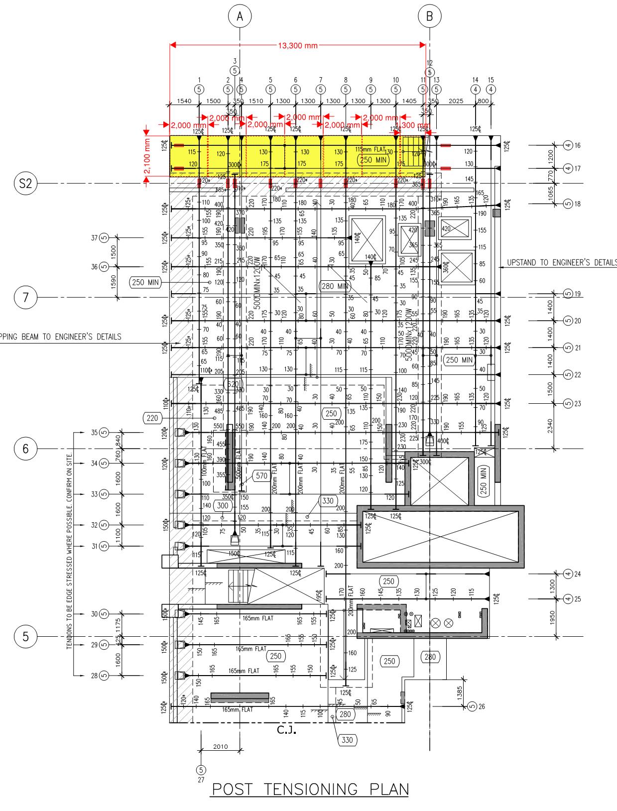
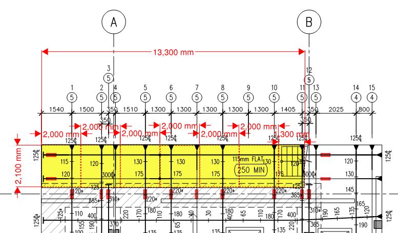
Step 3: We scanned the area to locate services and ensure PT ducts were as per the as-built drawings, they were. Step 4: Truncate the PT tendons 100mm past the line of cut (in the section of the slab remaining) to ensure the tendon remains stressed once the cut. The image below shows the entire slab, the section removed is highlighted yellow, the red rectangles represent areas of the PT duct which were truncated. A more detailed image is below it.
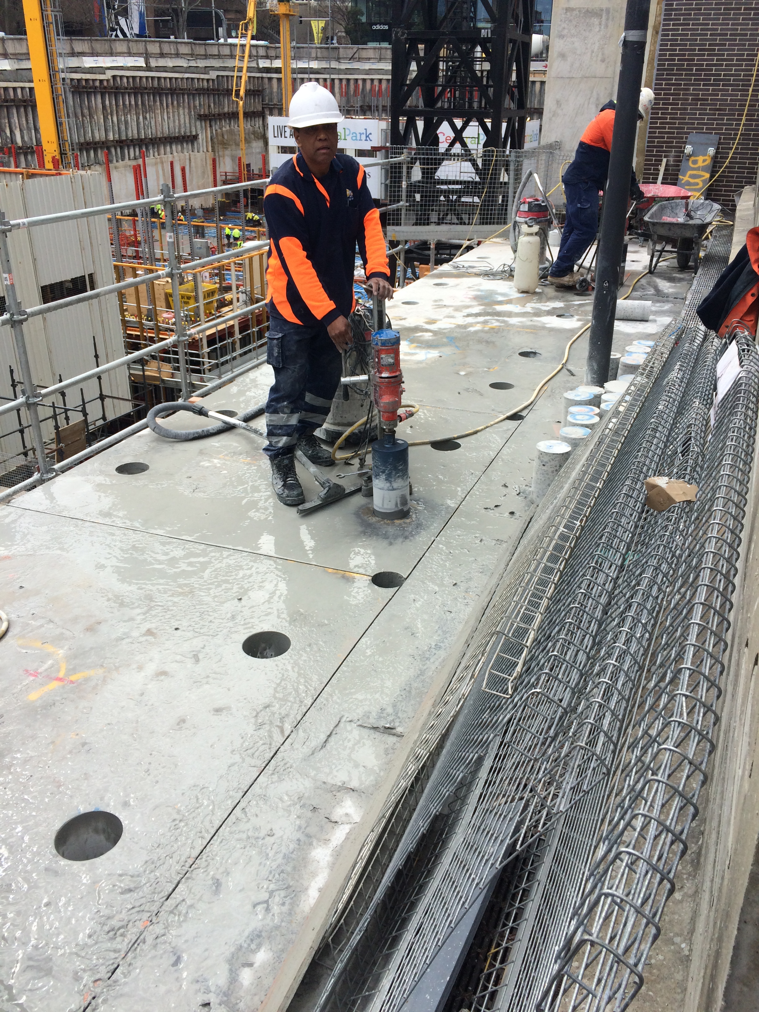
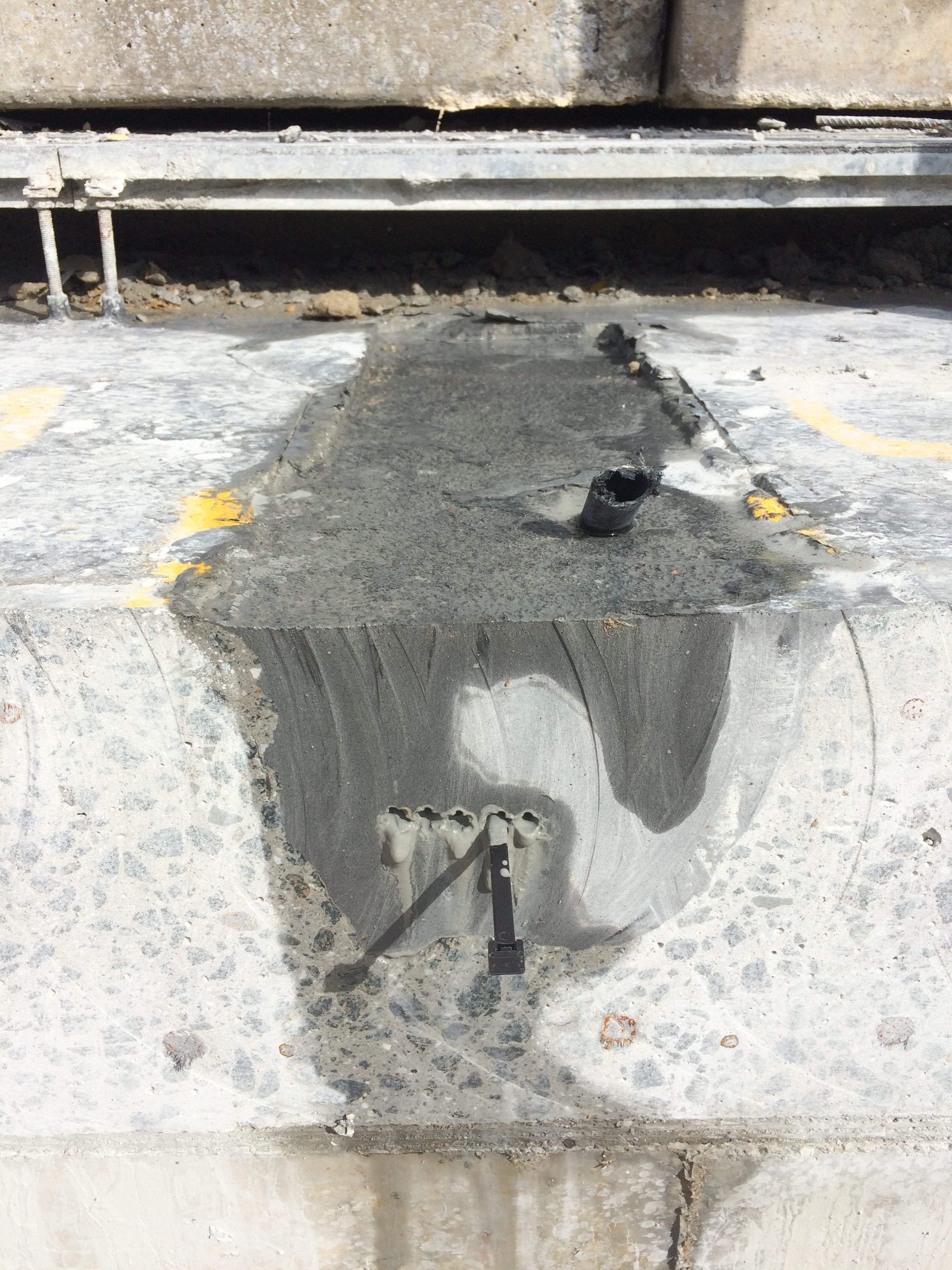
The truncation process involved removing a 500mm x 200mm by 150mm deep section of the slab to expose the PT duct, image below. The duct was then stripped back to allow inspection of the grouting around the tendons. The void was then filled with an epoxy which, once cured, acts as a plug to truncate the remaining tendon.
Step 5: Core holes were then drilled for two reasons… 1. to allow the sections to be slung by the crane crew, 2. to prevent the ‘road saw’ from over cutting at key locations.
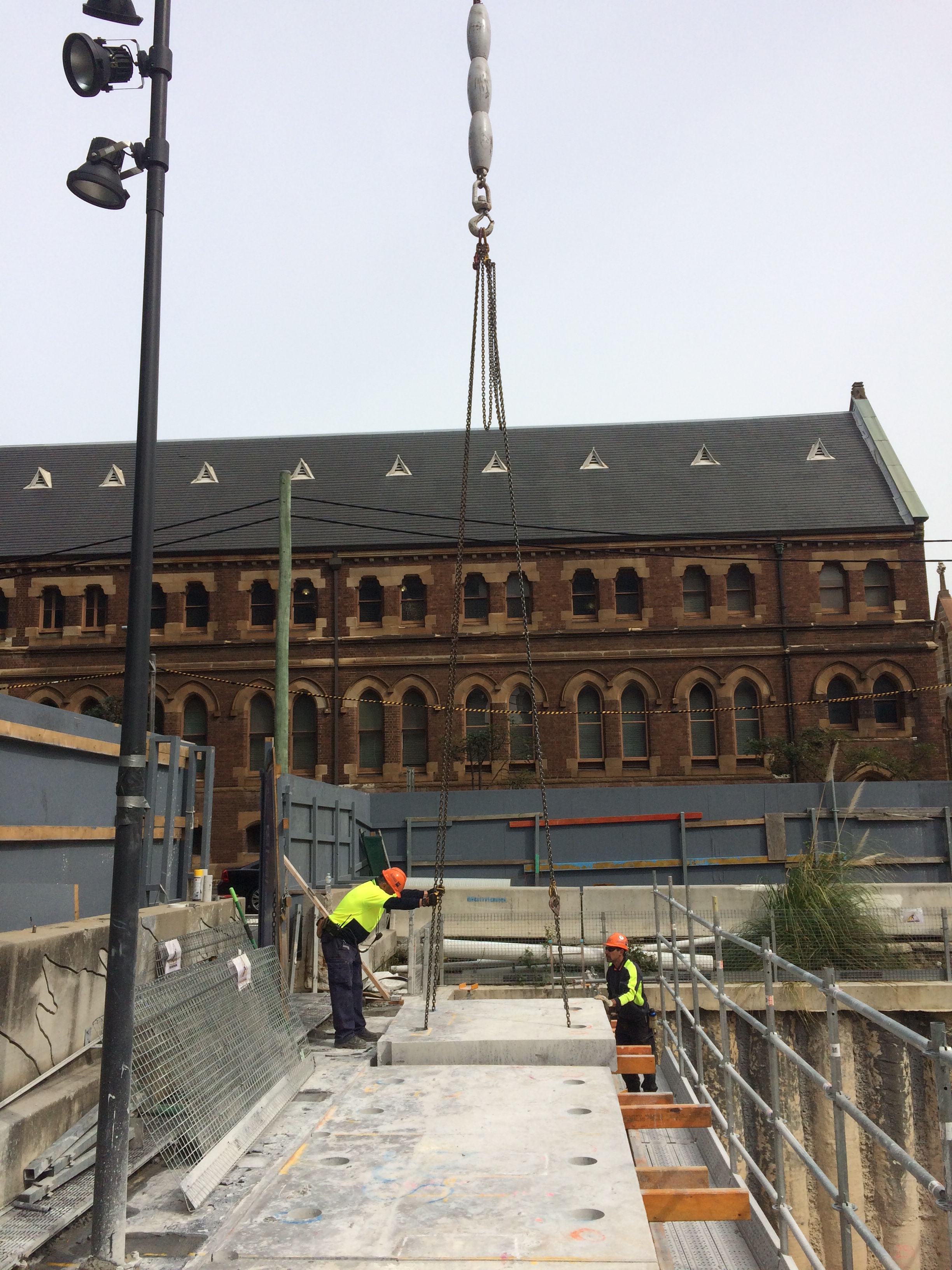
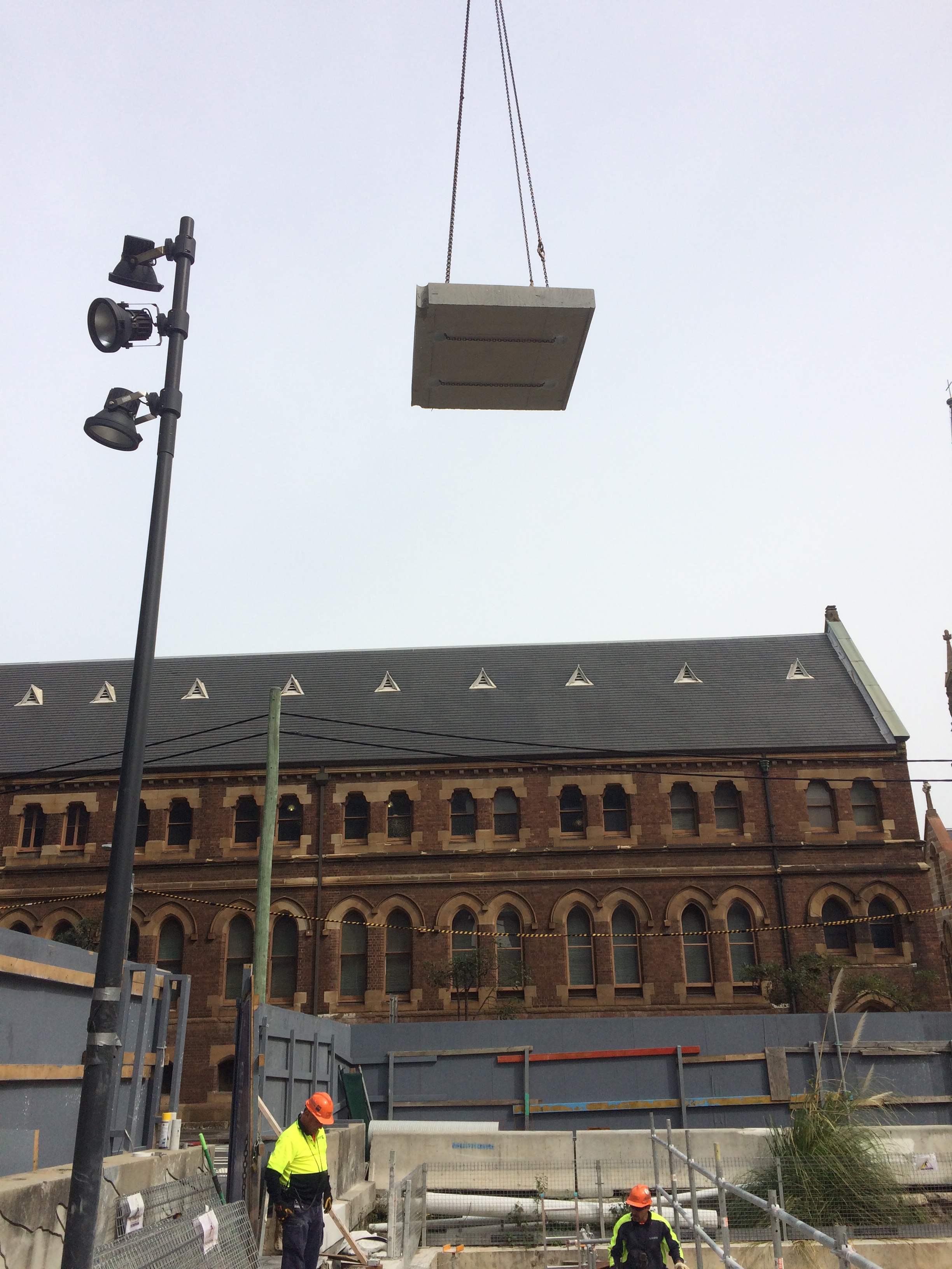
Step 6: The sections were then slung and lifted out for removal from site.
The final step involves treating the newly exposed PT tendons to prevent corrosion. On inspection we noticed that the PT tendons had slipped at 2 of the 12 epoxy plugs, one by 70mm and the other by 180mm. Initial analysis indicates that the slip is acceptable but an investigation is ongoing to work out why the slip occurred. In my opinion, it is worth noting that these two locations lacked grout around the tendons during the grout inspection. More is therefore being asked of the these epoxy plugs. It is also worth noting that the epoxy didn’t appear to be completely cured. In my opinion, these two factors are to blame for the slip, but hindsight is a wonderful thing and time is money apparently…
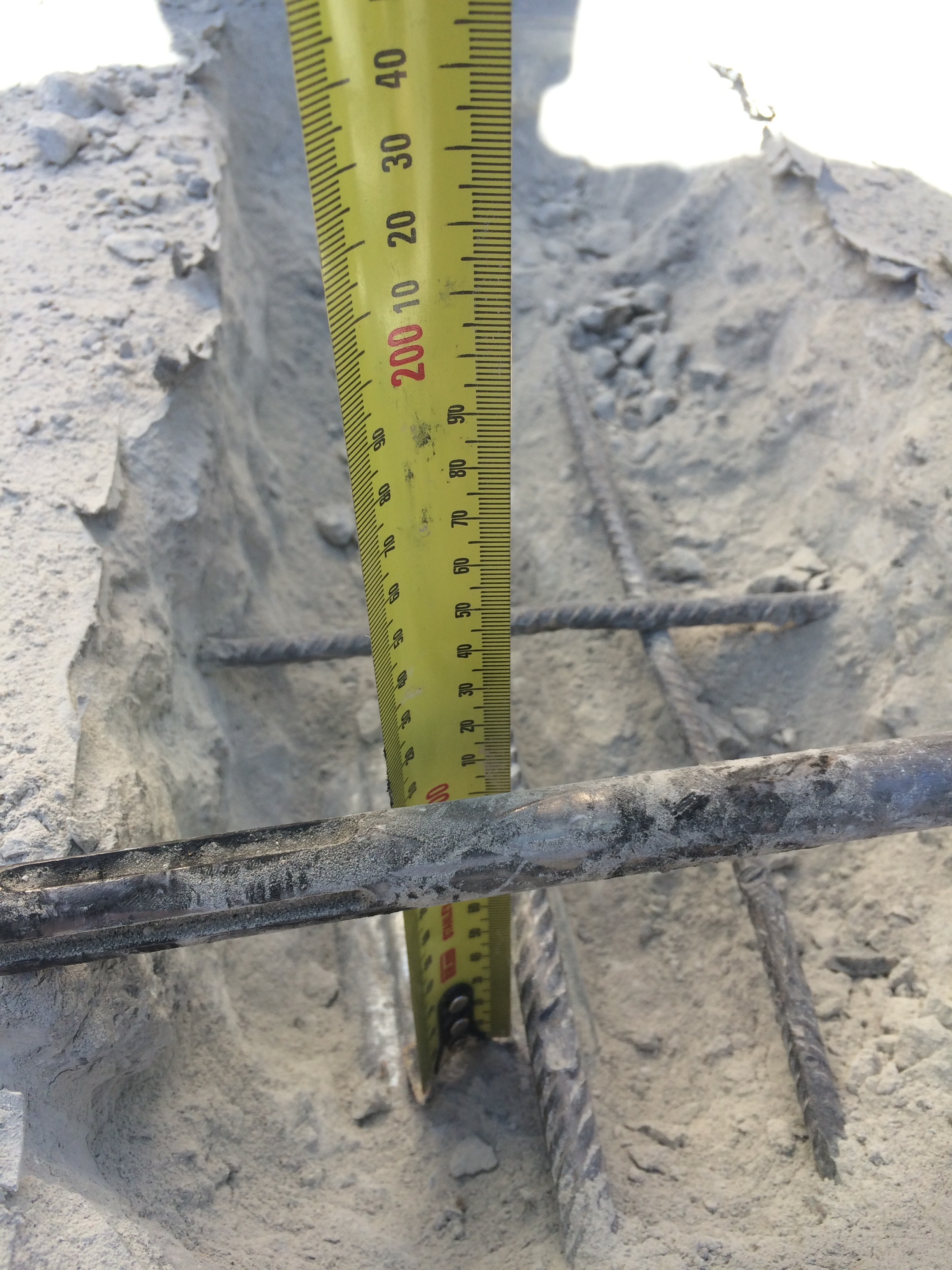
The image below shows the exposed PT tendon at the face of the cut. NB: no slip!
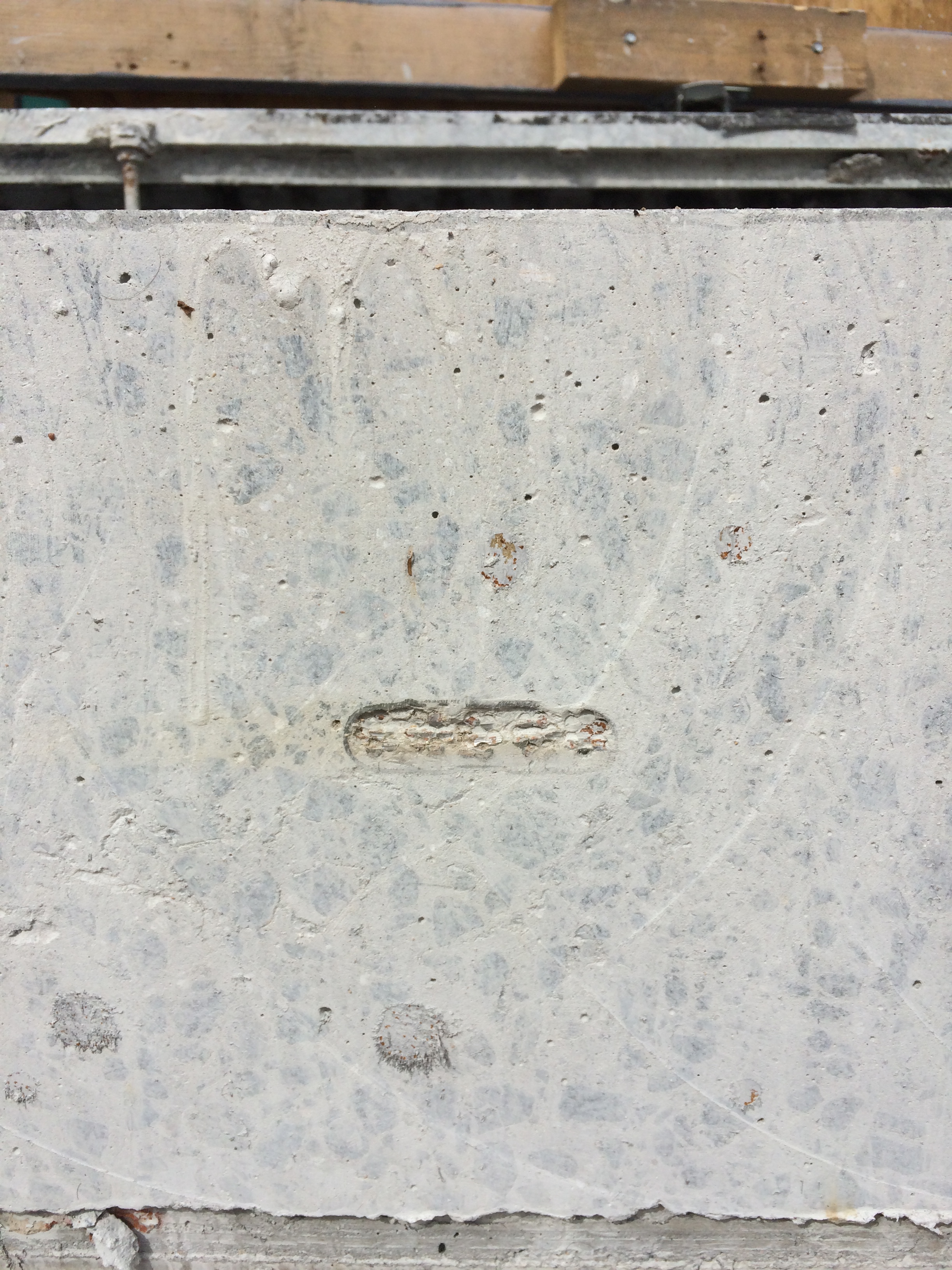
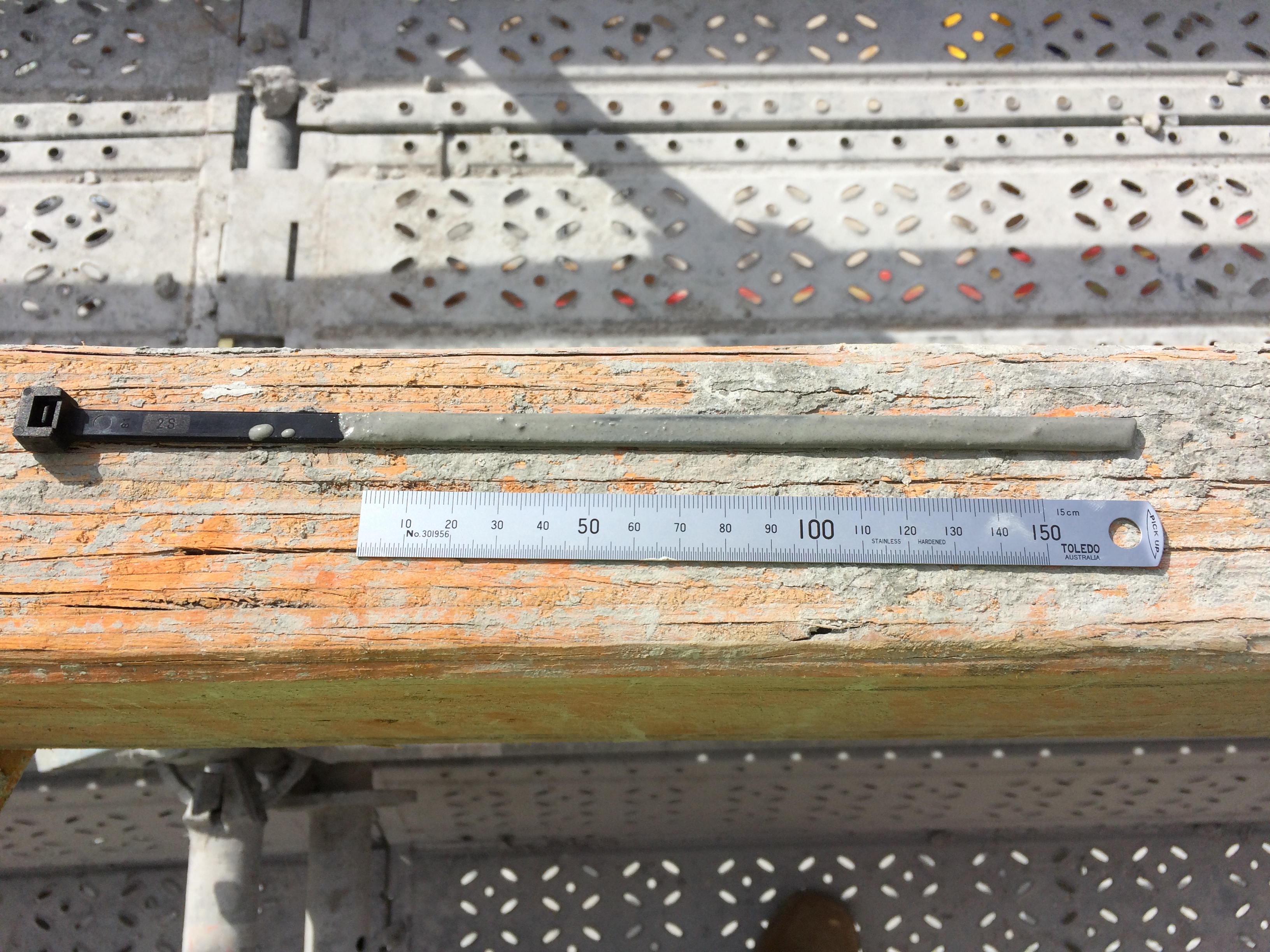
The image below shows slippage of the PT tendon at the face of the cut. NB: my high-tech cable tie measuring device!
More to follow…
