Archive
CDM – Who is responsible? Rebar Stability
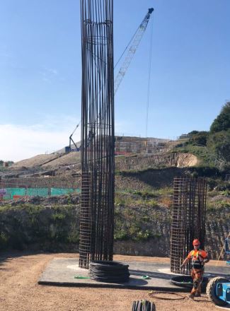
We recently had a temporary works problem on site involving rebar stability for the columns (picture 2) below. The sub-contractor has argued that the principal designer (PD) has given no considerations to buildability of the structure and has negated its responsibility under the CDM regulations. The principal designer argues that the temporary works are not their responsibility. The question arises: where the line is drawn for responsibilities in considering the buildability and structures in the temporary state?
Picture 1 – Example of reinforcement failure (not my site thankfully!)
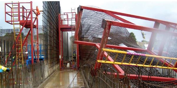
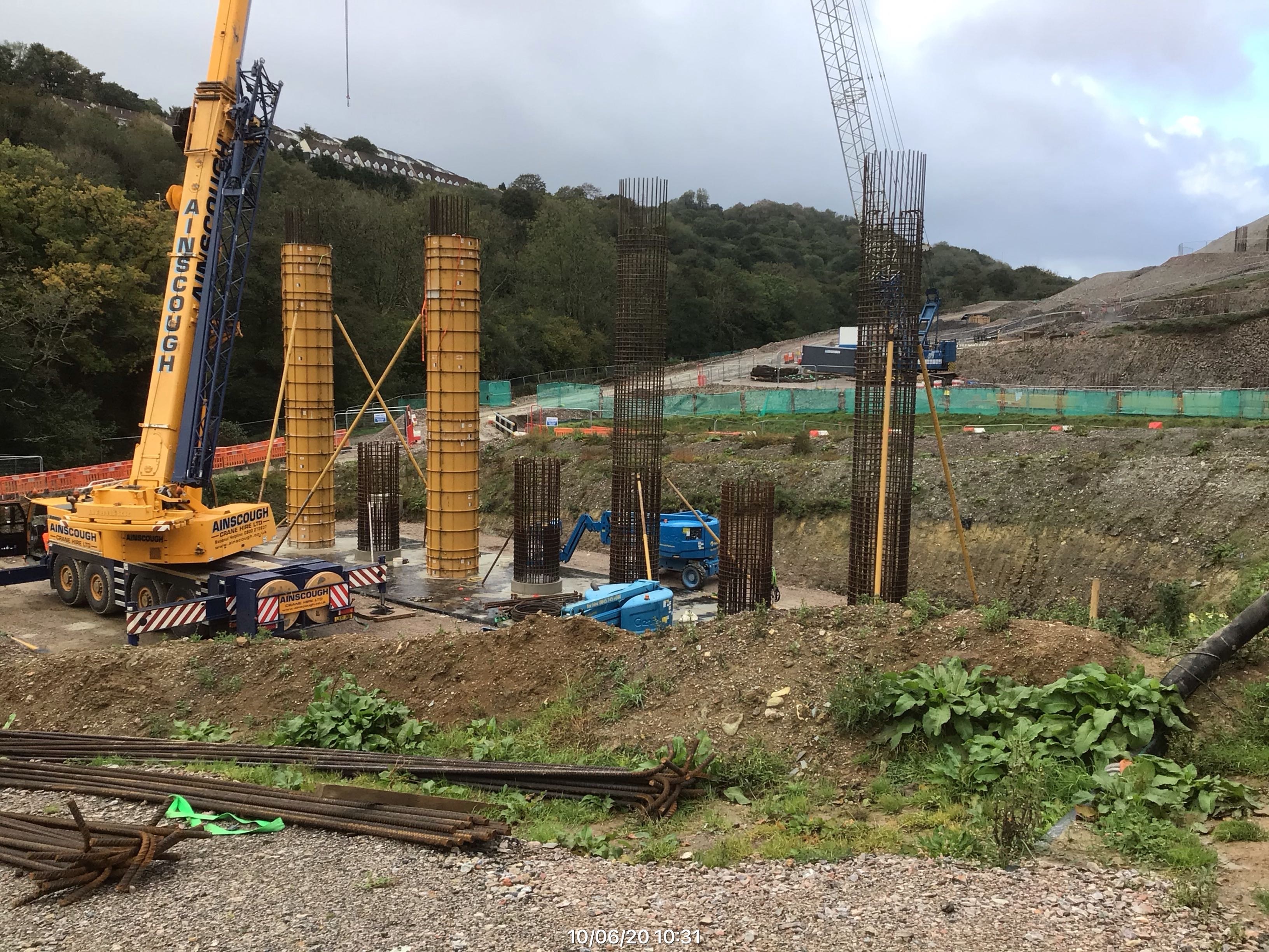
Picture 2 – Abutment columns with deflection (my site)
Picture 3 – Abutment Columns with temporary propping and kickers cast to support main bars
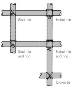
Picture 4 – different tying wire arrangements
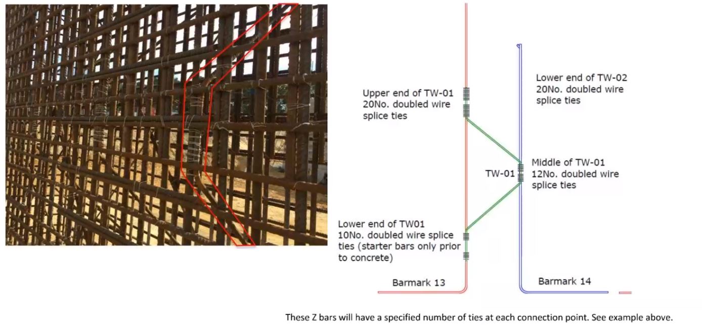
Picture 5 – Z bars and additional ties prescribed
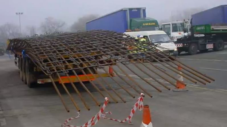
Picture 6 – Racking failure with welded reinforcement
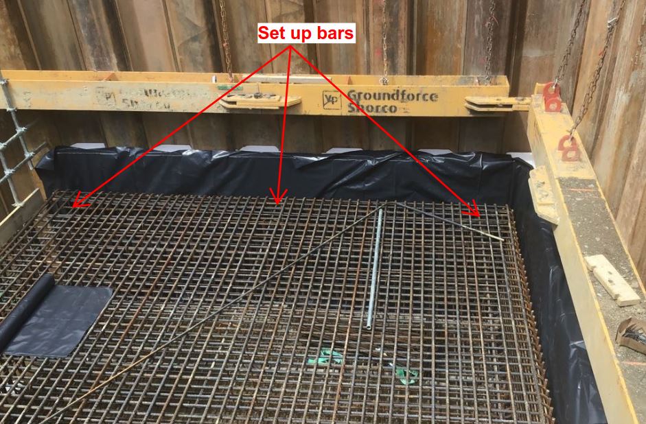
Picture 7 – Set up bars to aid fixing but can also be specified to support slabs
Personally, I think that any permanent works designer worth his salt should at least identify the specific risks in the temporary state. Merely, stating “temporary stability of the structure to be designed by others” is not acceptable in my opinion. As always time/money in the design office is always an issue as designers juggle several projects at any one time. Furthermore, I have experienced that some permanent works designers imply aren’t aware of the risks. How can the risks be eliminated if the risk is not known. Nevertheless, permanent works designers should always be receptive to design amendments proposed by sub-contractors an other designers to ensure schemes remain buildable.
The following website/blog produced by an independent consultant offers some interesting thoughts on the PD role.
The Temporary Works Forum (TWf) is an excellent starting place for any engineer. https://www.twforum.org.uk/home
For rebar stability, some (not all) of the failure modes and potential solutions are:
- Racking/Sway – diagonal z bars (square columns), propping the cage.
- Bending – erecting a one/two faces of a shutter before fixing steel or an access scaffold designed to support forces imparted by the reinforcement.
- Discontinuity Failure (ties fail/sliding of bars) – additional tying wire*, different tie patterns, welding of cages, casting a column kicker to allow main bars to rest on when connected to starter bars.
*1.6mm black – 280-320N/mm2 , 1.2mm stainless 600-800N/mm2 (TWf, 2020)
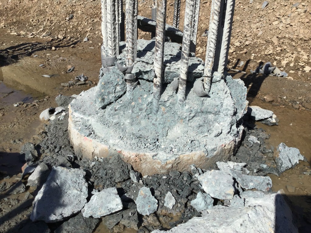
Pile Cropping
Debond, Debond, Debond!
An interesting loop hole/oversight, that we have come across on site. The main bars for the pile cage are de-bonded using foam down to cut off level.
The designer will never approve foam all the way down to cut off level in case of any drop in the reinforcing cages. (They allow 50-100mm). The piling subcontractor have a tolerance of cage level of -50mm and +150mm in accordance with the ICE Specification for Piling (SPERW). In this case, we have both extremes of +100mm and +150mm, which has resulted in 250mm of bonded concrete.
Normally, this would be easy using a pile cropper or diamond drilling company but not when it is bonded. Back to pneumatic picks by hand.
The drawings and tolerances were all checked by the piling subcontractor, principal contractor, designer and client’s representative. All failed to spot the issue, myself included. I would expect the piling subcontractor to be fully aware of the issue but again nothing was mentioned.
Contractually, nothing that we can do. The pilers are within these individual tolerances. Unfortunately, it falls on the next subcontractor to work through the issue. This means a lot of time and especially Hand Arm Vibration (HAV) as they work around the main bars.
The lesson here is even though the tolerances may appear acceptable in isolation. The sum of these tolerances have resulted in extra time, cost, and H&S risk.
The sixth sense…
At what point in an engineers career is he able to look at a problem and sense that risks haven’t properly been addressed…?
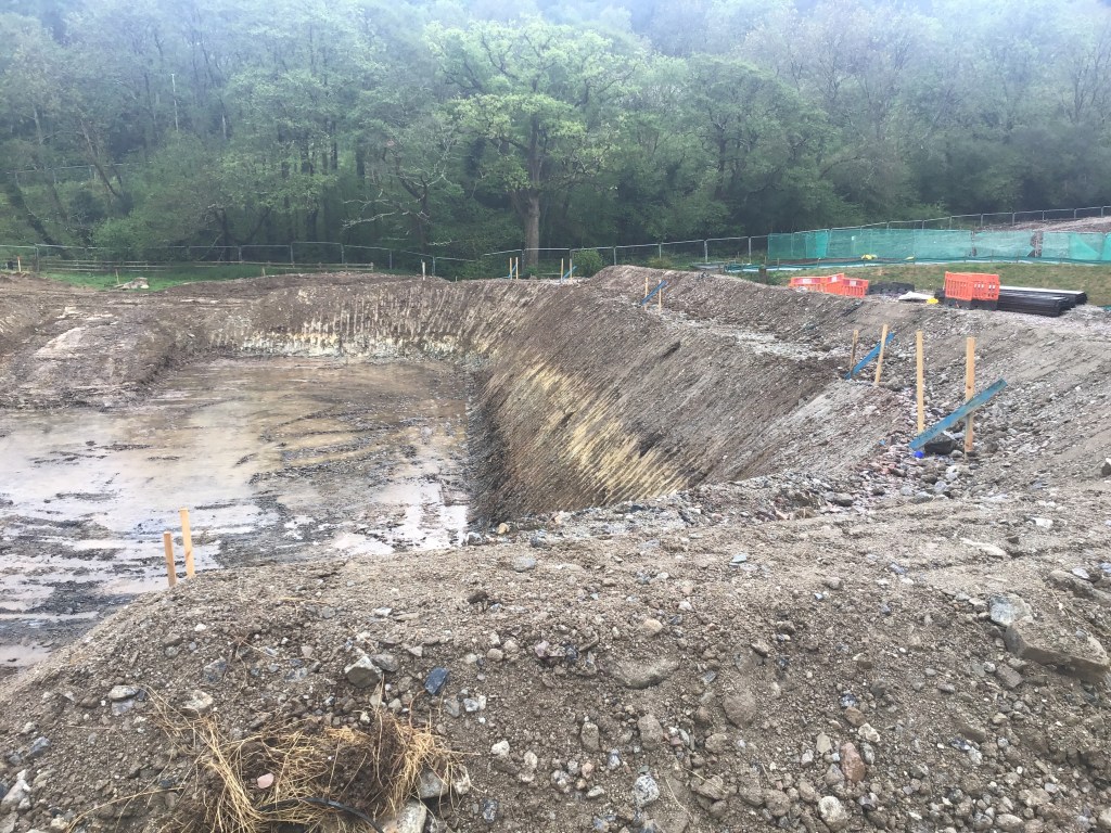
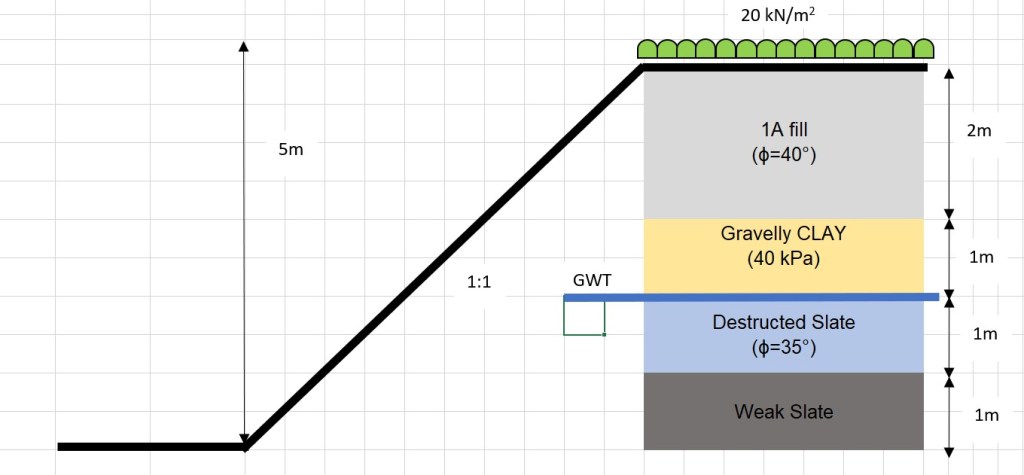
The risk in question here is safe. More specifically, slope stability of the excavation below. The slope is at a 1:1 batter at a height of 5m. The bund at the top of the slope (RHS) indicates the outer edge of the proposed site haul road (not yet operational), which will carry all laden plant. The bottom of the slope is ready for a piling mat for abutment piles. From this, I would suggest a surcharge of 20kPa at the top of the slope. The profile and design borehole is estimated below in the sketch.
Strength properties have been taken from the principal contractor’s temporary works (TW) team for other designs. If is interesting to note that most TW problems to which the site team having varying opinions
The approach/opinion to this has varied dramatically on site. The opinions are: 1) “It will be fine”, 2) “This needs assessing by TW”, 3) This is unsafe”. All project managers (10+ years experience) and all with civil engineering degrees.
What is your gut reaction? for this problem? for other problems? What problems can you rely on your heuristics to address the risks?
Experience is critical but training goes a long way.
My personal opinion (without analysis) is a suitable assessment with either GEO5 and Bishop’s method is required to propose a technical solution and manage risk. Furthermore, I would need to do some re-reading of the rock classification and discontinuities to determine if this is unsafe. I would feel semi-comfortable on doing some analysis on this and making the call on site without TW design. Perhaps a feature of a TMR in the future.
