Archive
My Passive is Active and piles might get pre-bored!!!
So yesterday I ended up chatting to Richard and John for a while with a question about how pre-boring affects the resistance of sheet piles in clay and how to model it in WALLAP. As I suspected the answer wasn’t a simple one!
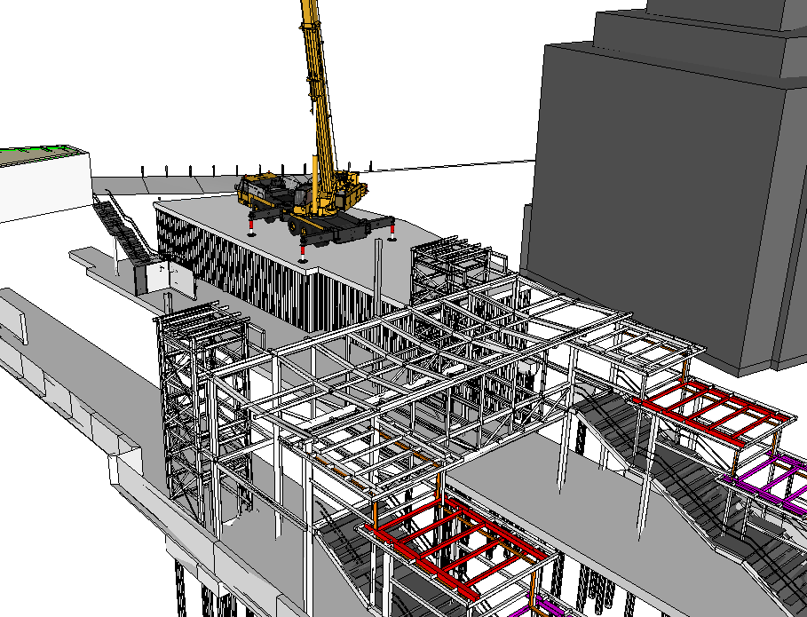
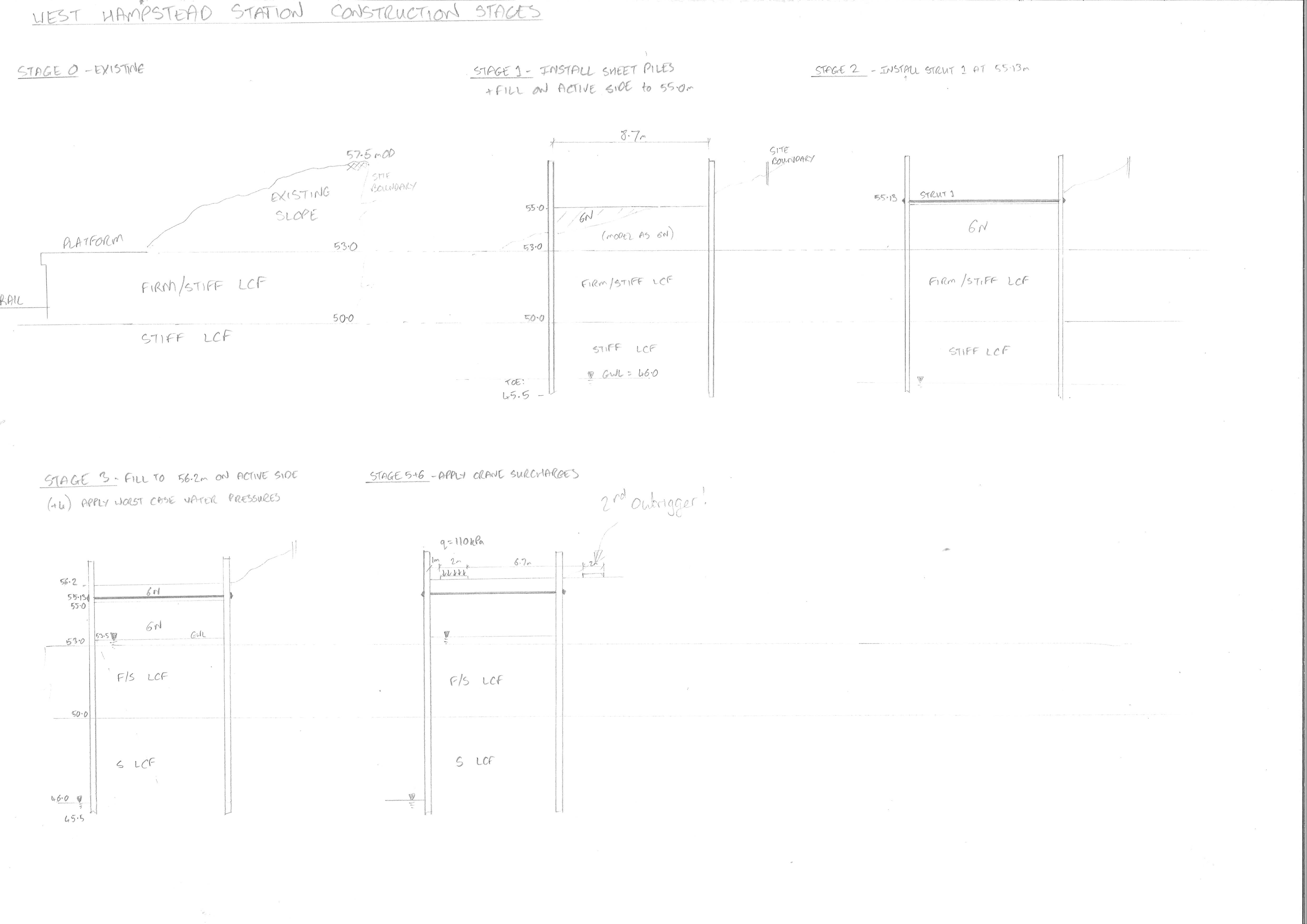
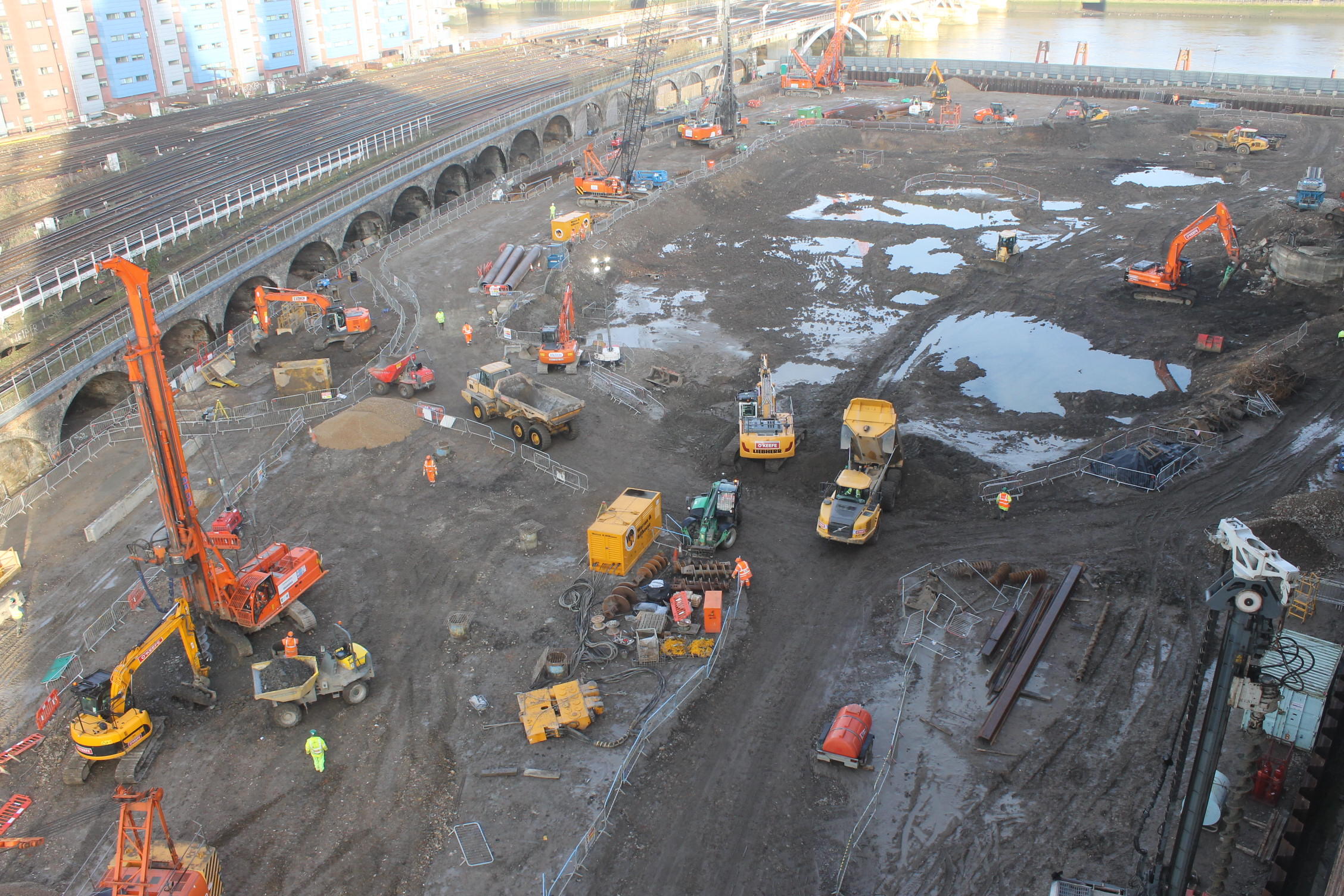
The retaining wall is part of the station redevelopment at West Hampsteadand were are designing a cofferdam that will act as the base of a new station building. It will also need to accomodate a large crane during the building of a new footbridge.
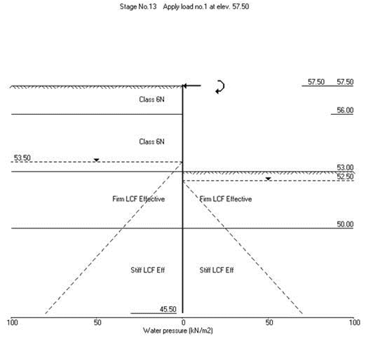
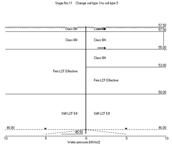
The ground consists of firm to stiff London Clay overlying stiff London Clay and we will use 6N (Granular Fill) inside the cofferdam. I used WALLAP to model the wall nearest the track to obtain the moments and shear forces and strut forces to enable us to design the ties between the the walls of the cofferdam.
Because the clay is stiff, it may need to be pre-augered to loosen the ground prior to piling. This has an effect on the stiffness of the surrounding soil and vertical resistance. The question was-by how much? After a long conversation with John I established that seeing as stiffness is unreliable squared then your guess was a good as mine! The solution was to do a sensitivity analysis by adjusting the stiffness parameters in WALLAP and see how much it actually mattered. The result wasn’t too significant so we have stuck to values of half of the undrained shear strength and half the stiffness values. We’ve also suggested water-jetting instead-has anyone had any experience of it on site??
Active and/or Passive??
The next part of the problem was modelling the far wall of the cofferdam. In theory because is was in level ground it is acting as a deadman anchor to the main wall using the ties. The ties forces were modelled as horizontal loads on the passive side.
Life would be straightforwards if that was simply the case but because that side also the active side of the main wall we have a problem where the two wedges interact. Since this is quite a common problem I thought there would be lots of literature on it but I was wrong! The BS CoP for Earth Retaining Structures simply says move your deadman further away outside of the active zone:
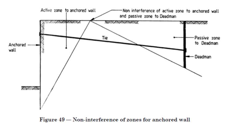
But we can’t do that as our second wall can’t be moved further out and it will become the piles for the building. So we have ended up just adjusting the rigid boundaries in WALLAP to reduce the amount of passive resistance available. It is a bit concerning that there isn’t much written about this when you think about the number of walls behind walls that are holding up various structures everywhere!
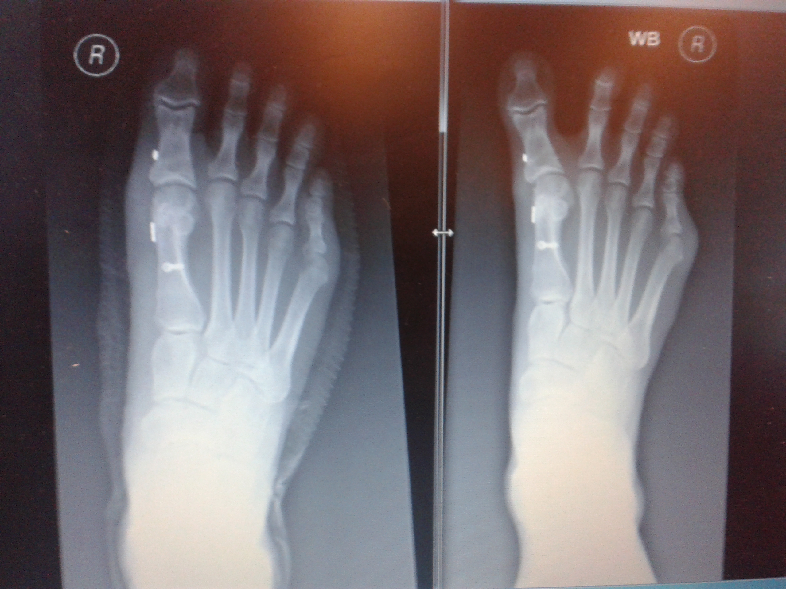
Unfortunatley it looks like my foot doctor didn’t do his maths on the forces that my foot goes through as my podiatrist sent me back to him for a review as my big toe looks a bit wonky again. You don’t need to be a doctor of engineer to realise that the piece of wire between the two metal buttons that goes between my big toe and the next has either snapped or cheese wired through the ligament holding it in place. The Xray on the left was post surgery in Jan and the right was last month. It looks like it will be 3rd time lucky with surgery on this foot and next time he will use wire meant for holding together shoulders and I get a month in my air cast boot 😦
Some additional info to add:
Well I think I had already done what John has said by drawing up this sketch of the Active wedge of the front wall (orange) and what is left available to become the passive wedge (pink) since we have a deep anchor we will have more passive resistance as shown by the pink dashed line too. I had a play around with WALLAP by moving the passive rigid boundary and it didn’t affect things too much. I will also have a go at making the ground slope on the passive side to see what that does.

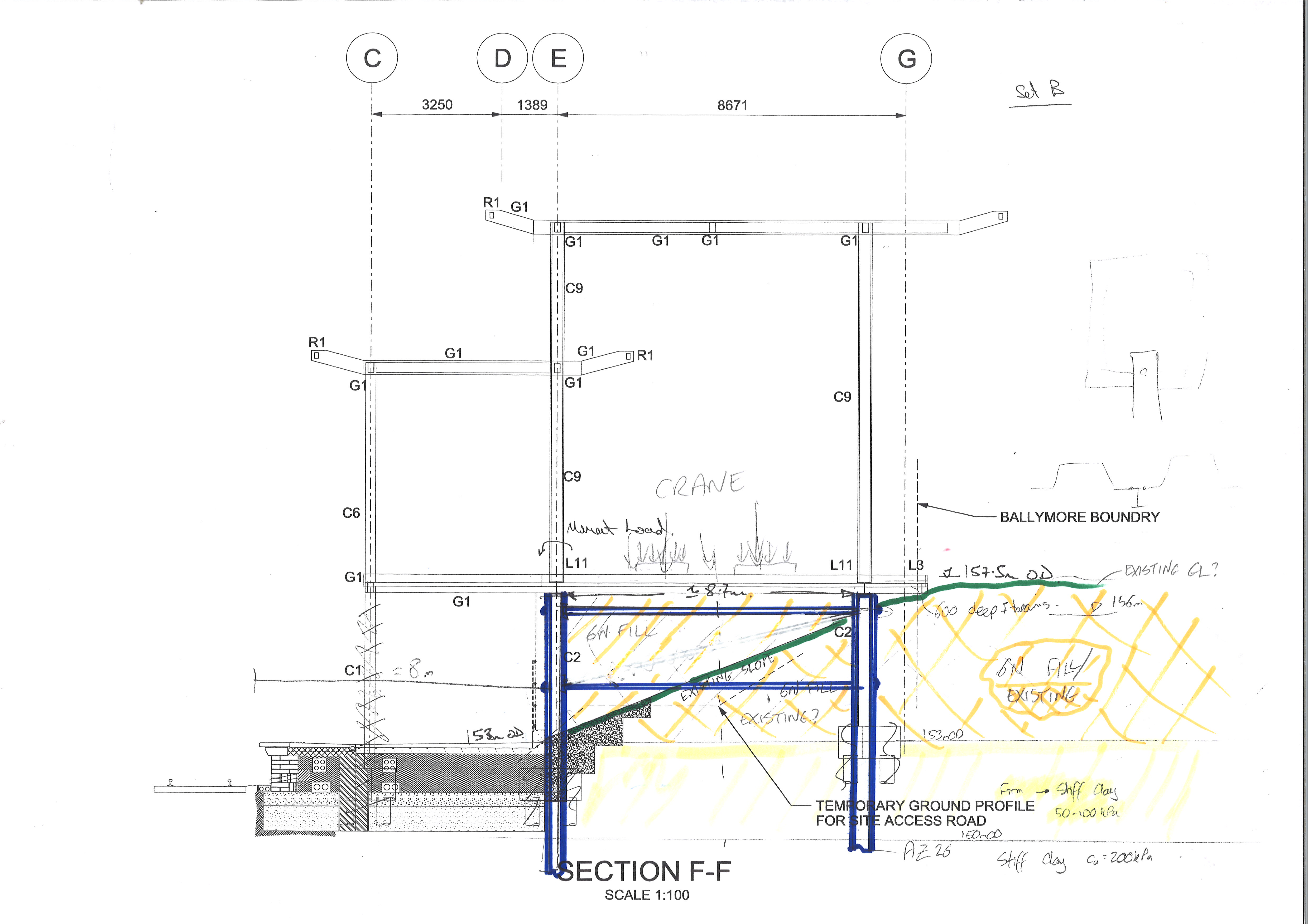
In response to Howards points here is a section view to help explain the bigger picture. The rear wall will become the piles for the back of the building and the site boundary is just behind it so we are restricted on anchor systems. Our worst case loading is the crane in the temporary condition so once the slab is in place and it becomes a building it ends up retaining less as currently the slab is suspended.
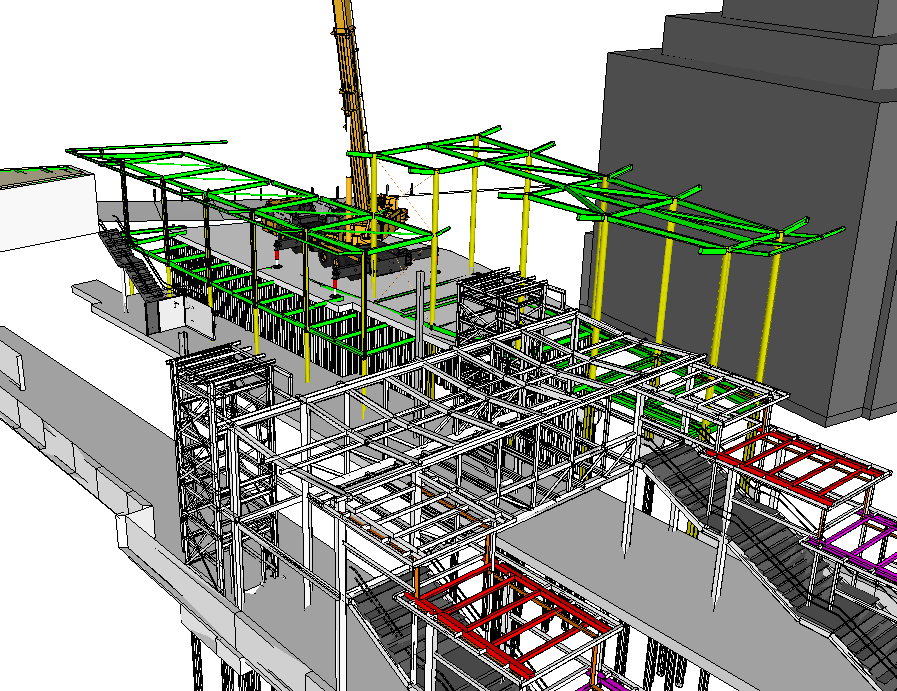
The railway team then decided to throw a spanner in the works and they now want an attenuation tank for surface water just below the slab so we have had to lower the crane and set up a new model. On drawing out the construction sequence I have found a much bigger spanner to lob around as I’ve noticed that their crane doesn’t fit!! I’ve just sent the email that no-one wants on a Fri afternoon saying that not even a crane 1/5 the size of what they need will fit in our cofferdam and they might struggle with the site boundary too!!
Back to Battersea
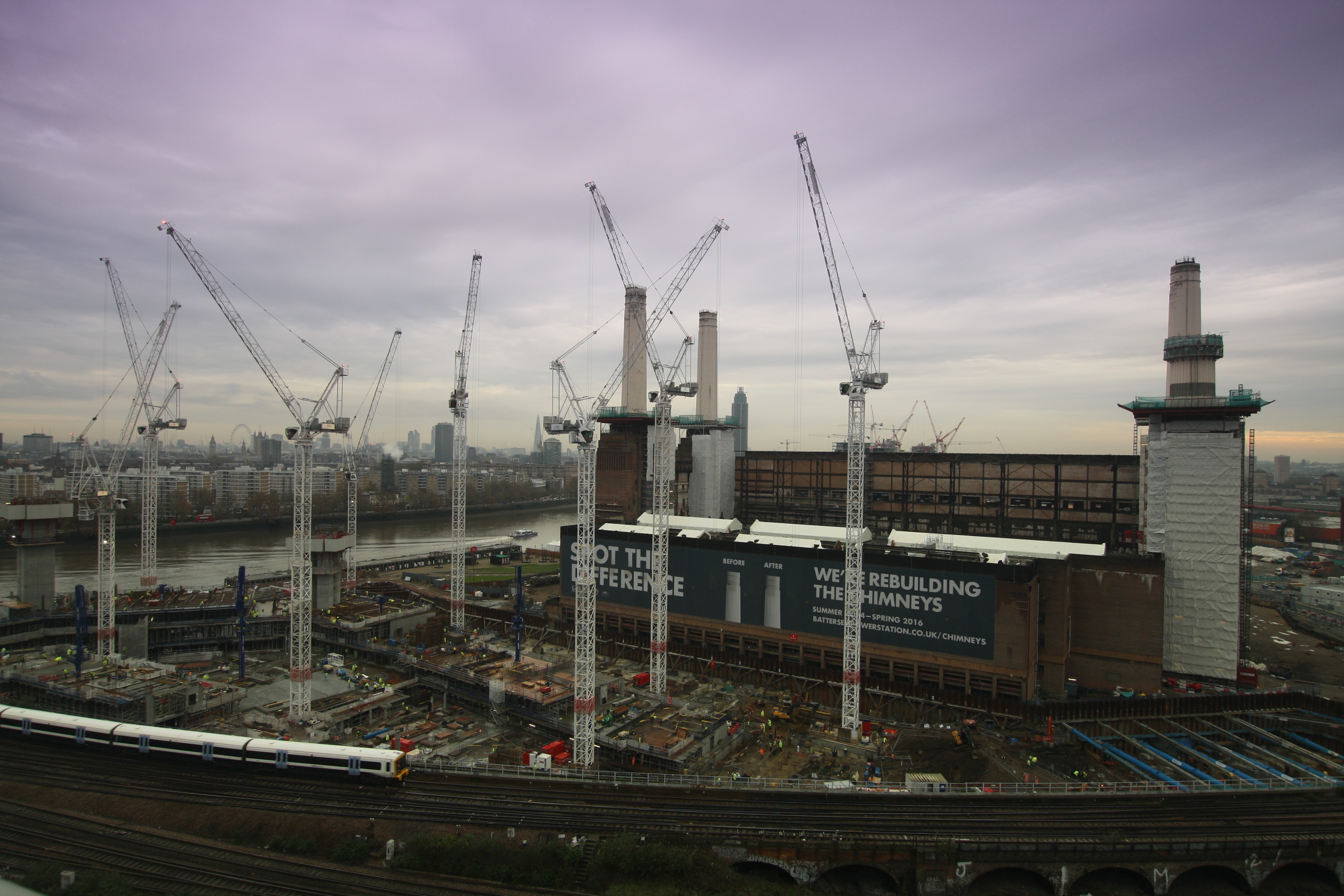
Well this week escaped the sleepy hollows of the New Forest to head back to the Powerstation to host a group of RE Senior and Junior NCOs on a H&S site visit. They are deploying to the Falkland Islands to construct a concrete pad foundation for a radar station being constructed by 39 ER. This was part of their pre-deployment training and an opportunity to see the H&S principals learnt in the classroom at Chatham in practice. I took the group round with my old mentor Richard and the ex-Grenadier Guards H&S guy who had started working at Battersea just before I left. I was pleased to say that they had actually made progress since I left and it was interesting to stand on the 8th floor overlooking the river.
As the group will be mostly working on construction of a large concrete slab, I concentrated the tour on the concrete pouring aspect of work. I showed them the area where Byrne Bros were preparing the re-bar for a large floor slab pour and I took the time to highlight the quality control aspects such as checking cover, bar diameter, spacing, formwork, etc. Later in the afternoon we were able to see the team pouring the slab and the group were able to take away a number of points to bring up with their chain of command. They noticed that the thick work gloves that they had been issued would not be suitable for the intricate task of wiring together rebar and that paper suits would be essential for concrete pouring even though the QMs department has deemed it too expensive.
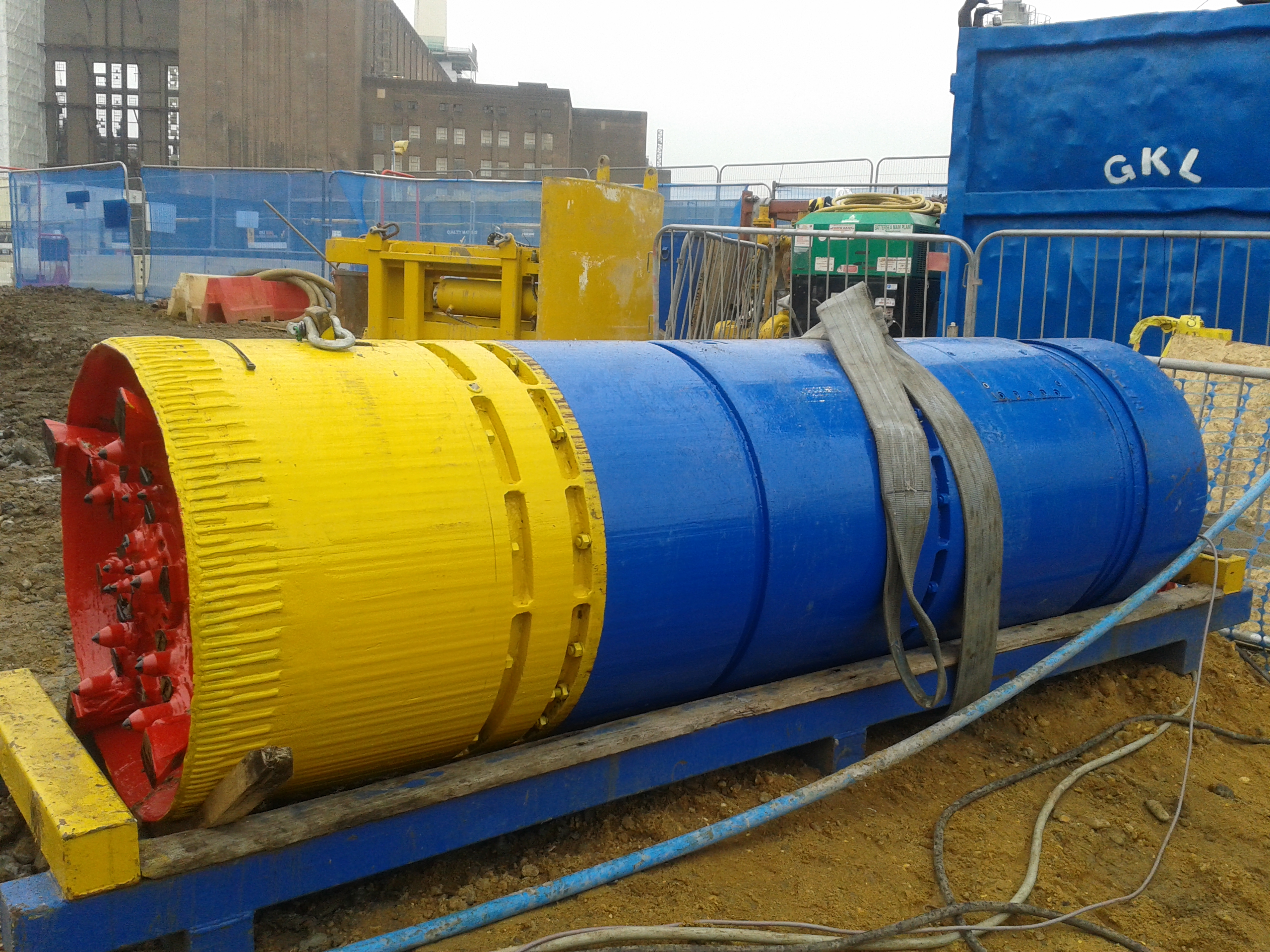
The group would also be installing drainage so I explained the Carillion policies on permits to disturb the ground and safety in excavations. I took them to view the final processes of the infamous micro-boring that has finally connected the foul drainage to the Thames Water trunk main. As I left Battersea they had just uncovered that the trunk main was too close to the Battersea Park Road bridge for them to retrieve the microboring machine. The team from Barhale ended up having to recover it from the Network Rail arch that runs underneath road. They constructed a steel girder gantry (see picture) over the reception pit to recover the machine and push it out of the arch using a miner’s railway track. Thames Water would not allow them to tunnel directly into the old Victorian sewer using the machine so the last few meters were completed using a traditional timber heading with soil grouting and de-watering. The total cost of the operation is now likely to exceed over £1m and is almost 4 months later than the planned completion date.
I think the day has been an extremely worthwhile trip and I felt that the H&S tour was a good opportunity for me to remind myself how much I have experienced and learnt on the placement. The guys were astounded by the scale of the project and they have taken away some good ideas to include within their pre-deployment training. I think we should encourage more trips like this for the artisan trades back in units to learn more about industry standards and large scale engineering projects.
Back at the ranch in Poole I have been plodding on with some breakwater design analysis of the super port in Morocco and I have also been given a smaller task of the Cat 3 design checks on a small boats marina in Gibraltar. John will be impressed that I have done some hand calcs for bearing capacity and settlement all by myself but it hurt my brain! I also had an escape from the office for a trip with the Army XC MTB to Cyprus for our training camp and to compete in the (not so) Cyprus Sunshine Cup, the first UCI stage race of the year. There we were competing against Olympic medallists and World Champions in a 4 day stage race including 2 days covering 50km each in the mountains. The final day was just 2 laps and a start loop on the XCO course that looked more like a Chamonix black downhill course but you had to ride up the back of the rocky drops in lycra! The race started pretty badly when I was wiped out 20m from the start by my fellow Sapper teammate Maj Charlie Batty. I think thought the photo evidence proves that I had overtaken him though!


My eyes hurt.
Well life is slowly but surely becoming relatively normal again after the worst Xmas ever. The combination of a foot operation the week before Xmas, my garage (which was my AT store) being burgled the day before the foot op and no skiing was pretty depressing. Thankfully the New Year has started more positively and I have settled into the design office at Ramboll in the New Forest quite nicely.
Just as Rich Phillips had warned me, it is a bit quiet but everyone is very nice and extremely helpful. The pace of life is much more sedate and for once I am not the biggest geek in the room! Luckily I sit near a guy who is also a very keen mountain biker and behind a girl who has just finished her geology degree and is keen to explain principles to me. Rich has paved the way in what they expect and what sort of things we need to cover so thanks Rich if you ever read this!
My first task has been of mammoth proportions. Ramboll have been tasked to come up with a design for a breakwater for a port out in Morocco. Initially I thought great, you just design the core, protective rubble layer, do a bit of maths for settlement, wave and boat impact loads and off you go-WRONG! This breakwater is 3km long in 35m of water and a purely rubble breakwater would have needed to be 450m wide! To add to the problems it would be founded on around 8-10m of soft silt which has the compressibility and strength of a soggy bathroom sponge. Ramboll changed the design to be a rubble mound with a concrete caisson (30m wide and 35m tall) to bring the structure above sea level.
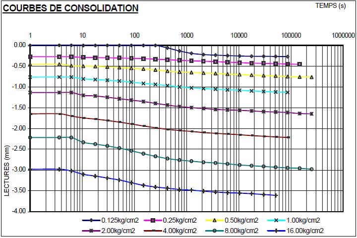
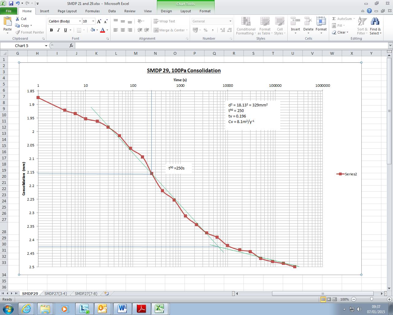
My initial task was to go through the 1D oedometer tests (which were all in French) and re-plot them on bigger axes to be able to establish the primary and secondary compression lines of best fit. This meant getting my head back into the books to understand the oedometer test and the theory of consolidation. I then had to calculation the coefficient of consolidation (cv) using the Casagrande logarithm of time fitting method. This involved plotting lots of points, fitting lines, measuring time values and calculating cv on a spreadsheet. The work was quite time consuming and monotonous and it hurt my eyes but it was a good opportunity to fully understand some theory.
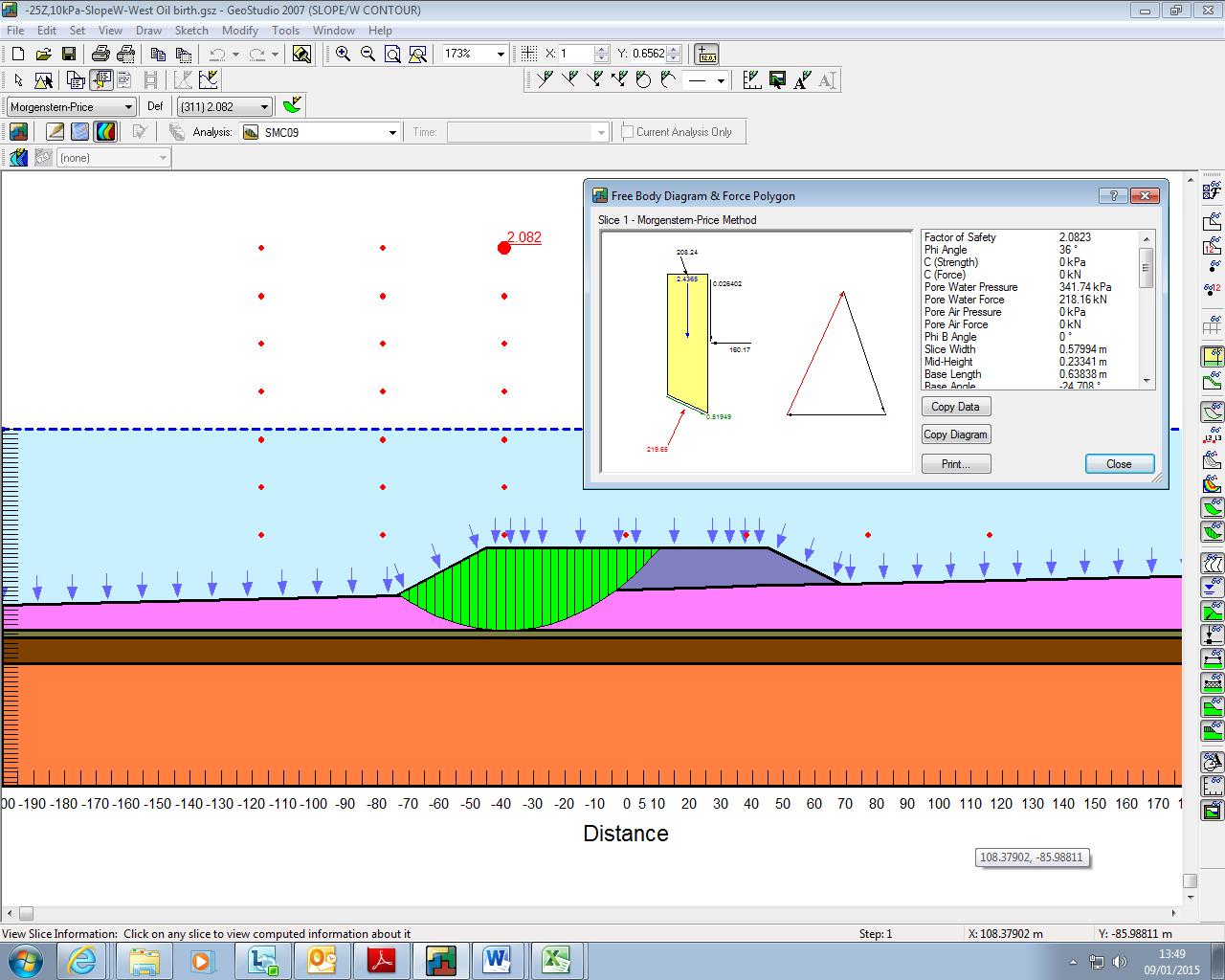
My second task on the project was to model part of the breakwater using the slope stability software SLOPE/W. Firstly I had to input the geometry of the problem and assign the initial material parameters which was the easy part! The software then calculates potential slip surfaces using stability of slices within a slip circle. The output is a factor of safety which must be above 1.15 in the temporary condition. I had to break the model down into stages starting with just the breakwater structure, then the concrete caisson followed by layers of fill in the caisson. Again this initially sounded simple until I had to incorporate the increase in strength of the silt due to consolidation. I had sudden flashbacks of John’s lecturers hammering against the board trying to get us to explain the difference of drained and undrained parameters. Well John, having read a few chapters in Craig’s Soil Mechanics book I think I get it!
The theory. When a fine grained material is loaded it is compressed and initially the load is taken by the pore water resulting in an increase in pore water pressure. The initial (undrained) strength is quite poor which is why fine grained materials often fail suddenly on loading (John’s grain silos). The excess pore water pressure dissipates at a rate depending on the permeability which results in the primary compression part of your 1D oedometer test curve. We also added vertical sand drains which shorten the drainage path and speeds up the rate of consolidation. As the excess pressure dissipates the load is transferred to the soil skeleton increasing the strength (drained conditions). Is that right John???
My task was to calculate the increase in strength after each month and adjust my model parameters accordingly. This became increasingly complex as different parts of the silt under the breakwater had different loading for varying durations. I finally managed to create a crazy spreadsheet and I got my model to take a caisson that was half full over around 4 months when disaster struck. The next 5m of fill caused a collapse even if the silt was left to consolidate 100% after the previous loadings. So it won’t work, back to the drawing board! One of the other guys has also been modelling the seismic effects and the structure also fails in sliding so we are now considering steel piles, it’s going to be one expensive project!
I have also been working on a project closer to home near Bermondsey station with part of the London Bridge upgrade. I had to understand the Bermondsey Dive Under Box concept of construction and write a specification for new trial holes as some of the low headroom bored piling did not work with the ground conditions. I suddenly realised that it’s quite difficult to dictate where the holes need to go having never been on site and only seen drawings of the proposed structure. I now feel really sorry for the design engineer from Buro Happold who I got really annoyed with at Battersea for wanting to put boreholes in really inconvenient places!
In summary I think this will be a good placement with plenty of support for CPR and a nice working environment. I actually get the time to sit and understand the principles before I start number crunching. The commute is okay at the moment and it is nice not to have to drive back somewhere on a Sunday evening, let’s hope I don’t end up posted to Kinloss next!
End Ex at Battersea
End Ex was called for me at Battersea on Friday and as I handed in my phone and PPE I realised that I had outlived the Project Director, Construction Manager, Construction Project Manager and the other Sub-structure Engineer! There were only 2 others in the original construction team that had lasted longer than I had!! To me that suggests that the grass is not much greener on the other side and that this project was certainly taking it’s toll on the workforce. My task back in Feb was to complete the installation of the utilities and Network Rail Road by the 26 Apr. Here is what actually happened and why:
-High Voltage Cables (power on planned 1 Apr): Actual power on: mid-Oct due to client not completing the contracts with the shipper and meter operator.
-Potable Water: Pipework installed on site, still awaiting pressure testing, swabbing and chlorination which can’t be achieved until just before the final connection to Thames Water-they still haven’t got the pipe over Battersea Park Road yet.
-Comms: Ducts installed but BT are yet to bring their infrastructure to the site boundary.
-Gas: Not even designed properly yet!
-Foul drainage: See microboring.
-Surface water drainage: No pumps installed yet as they haven’t been ordered, outfall to the Thames has been redesigned to accommodate Northern Line extension works and a new flood defence consent is required.
-Network Rail Road: Part opened on 26 Apr but remainder not opened till 30 Jun due to the requirement to install a second retaining wall. The road was then not wide enough and has already been dug up a number of times to pull temporary HV cables and find water hydrants.
-Road Retaining Wall: Completed on time but part was broken out by the concrete frame sub-contractor for access to arches.
-Microboring: Much to my amusement the microboring machine was still sat outside the launch shaft on Friday afternoon when it was meant to be halfway under the road by then. On digging the reception shaft they found that the sewer was actually 1.5m closer to the bridge than they thought, leaving about 0.25m to get the 1.75m machine out of the ground! I refrained from shouting ‘I told you so, should have gone with pipe-jacking!’
So in terms of grand achievements part of me feels that I have failed but they have all been as a result of the large complex moving parts of the project or client and third party involvement. The only thing I would do differently is be stricter with monitoring the Quality Assurance of the sub-contractor as they got away producing extremely bad ‘as built’ records and some mistakes were made with connecting ducting. Until the project employed a Quality Manager we were making it up as we went along! On a positive note I have learnt a huge amount on the project especially from a contract management, quality assurance and health and safety point of view. Now I need to just turn my DO’s into ICE speak to prove that I have been achieving everything.
Here’s a start and finish picture of the project showing that we have actually achieved a hell of a lot on an extremely complex site with many constraints. I think Rich G will have an interesting time there and enjoy being part of such an iconic project. They can certainly do with some military help in terms of planning and co-ordination!
Feb 2014-a muddy puddle!

Nov 2014-Upwards progress in the north and excavation almost complete in the south.
A job with a view!
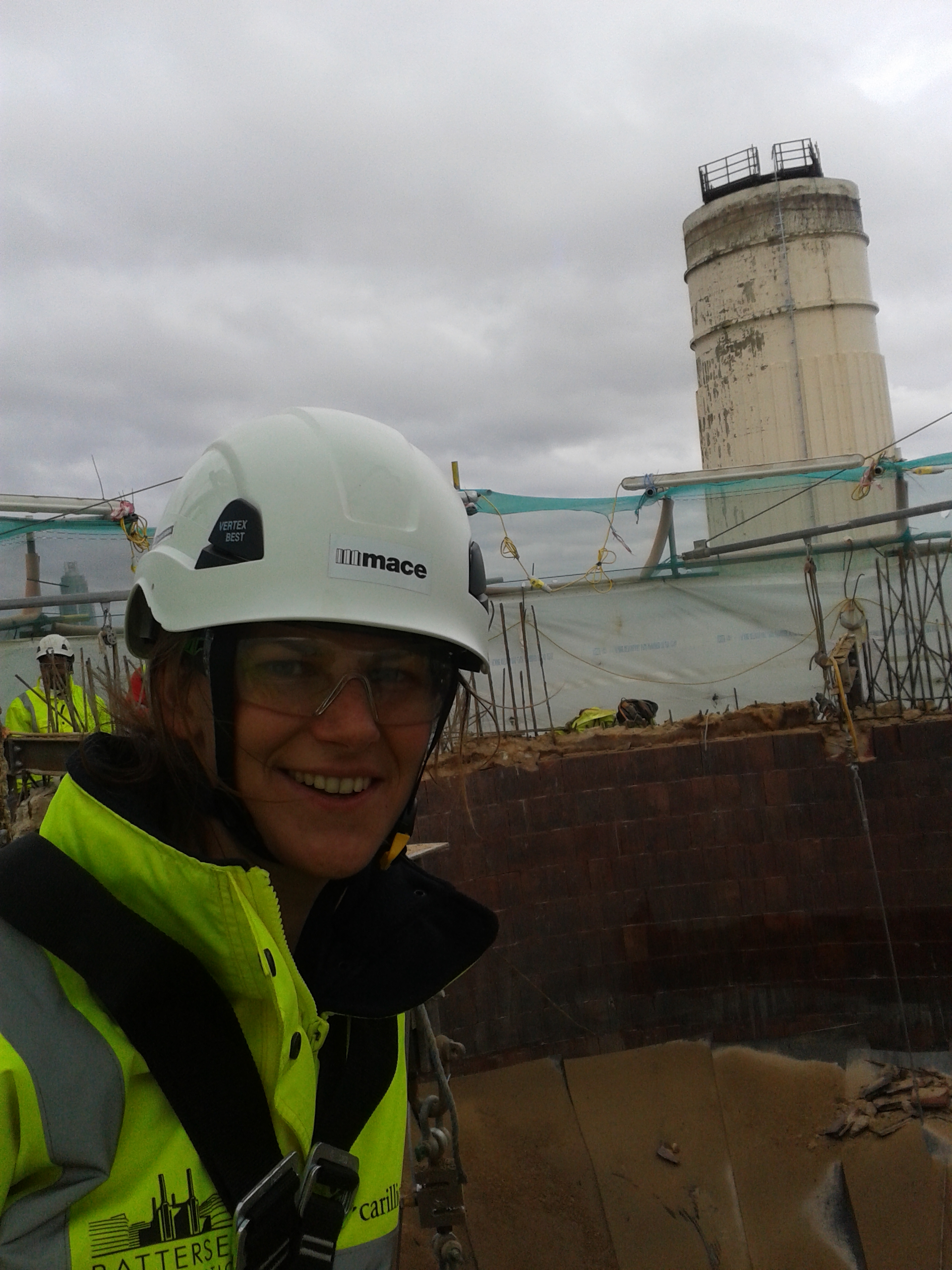
I finally managed to make a contact over in Mace by randomly chatting to the Project Director on the walk to site. He put me in touch with one of the engineers to chat about some of the technical issues who then put me in touch with a construction manager to organise my trip up a chimney! Having told him that I was a climbing instructor he quite happily gave me a full body harness and a glide-lock fall arrester off we went on a nice windy day!
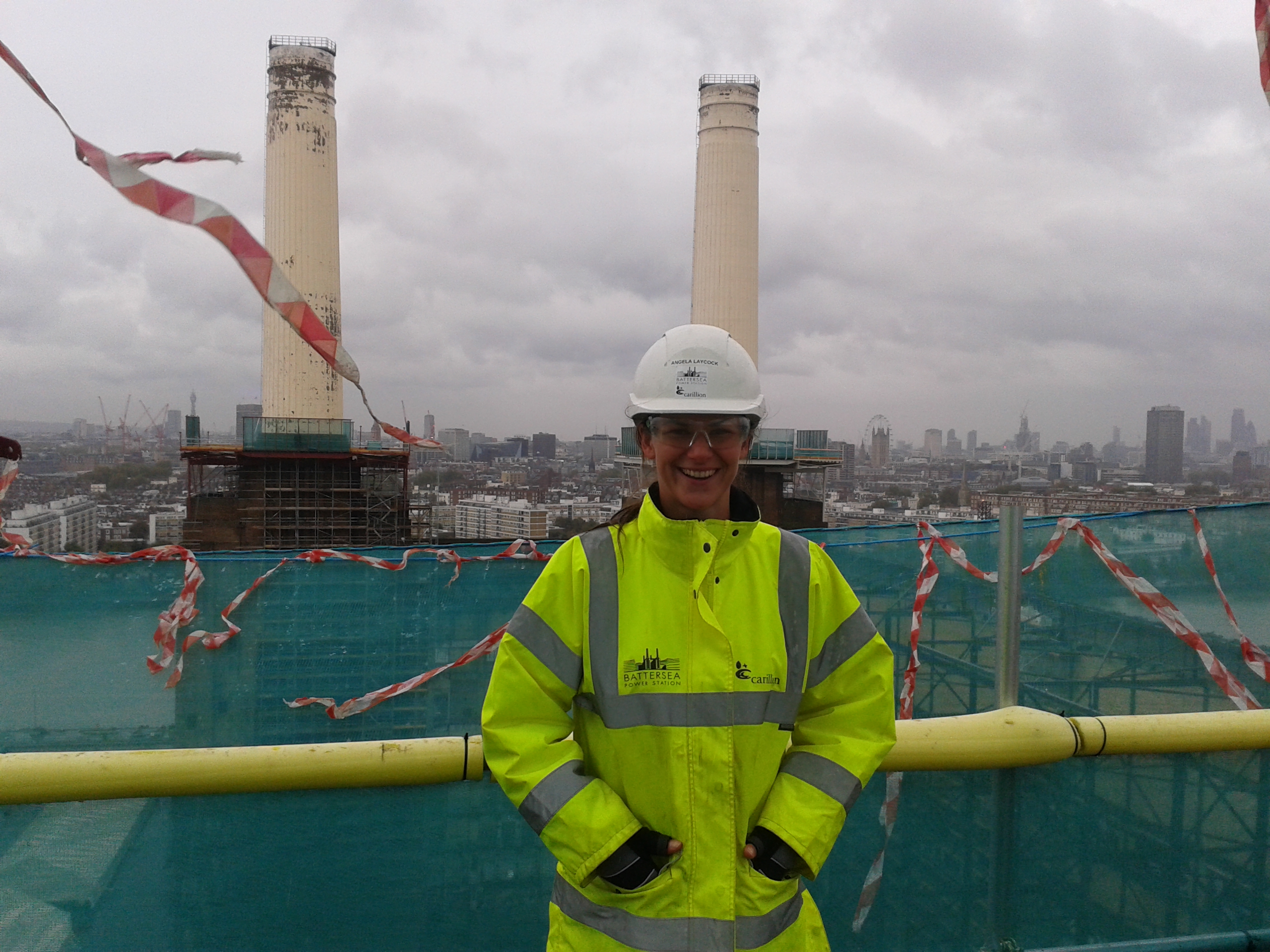
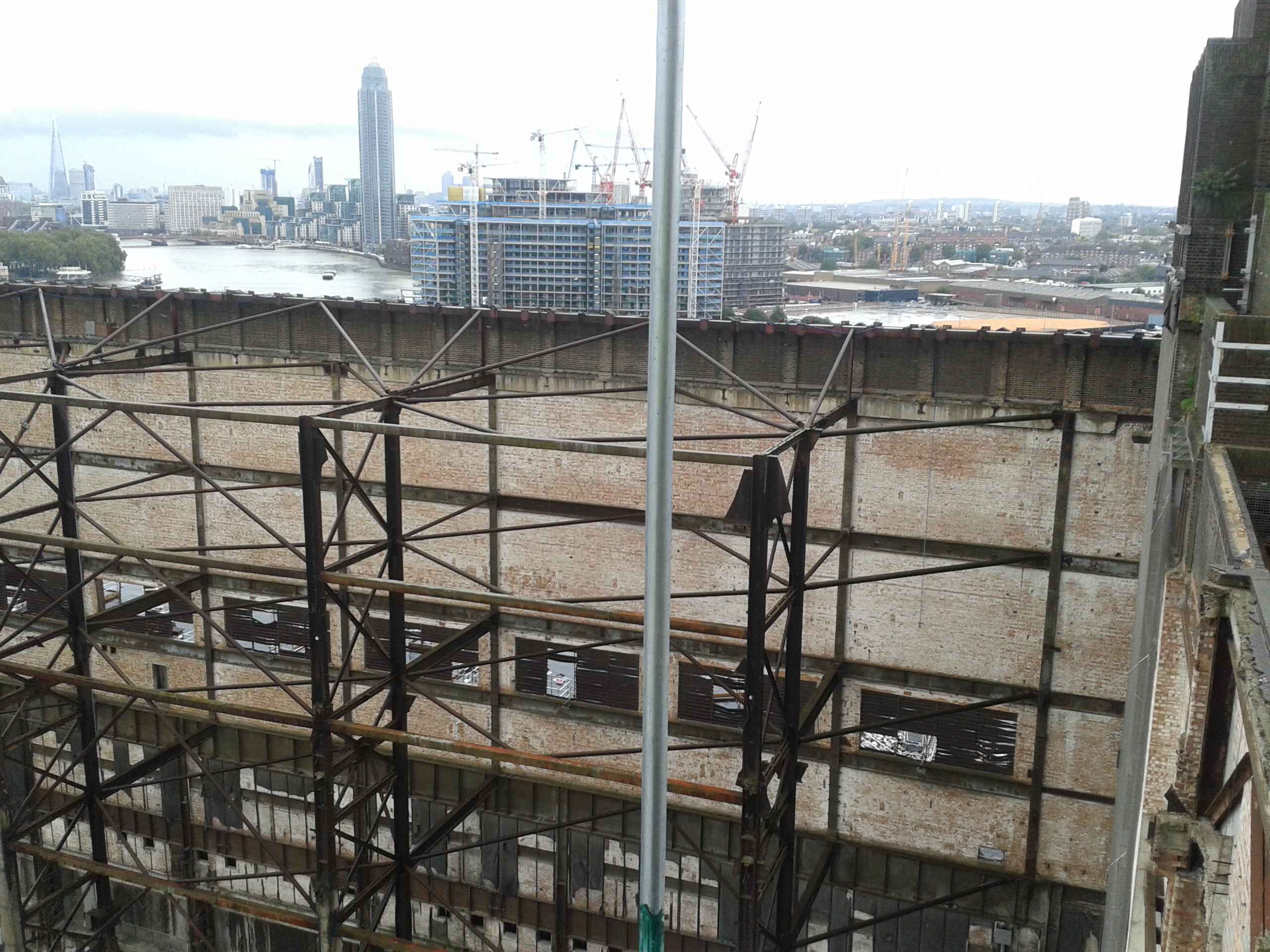
To get up the chimney you first catch the hoist up to the 14th stop which takes you to a level of scaffolding around the top of the brick wash tower. From there you climb up a couple of platforms via ladders until you are on the large protective platform that is designed to contain any spoil which falls from the demolition of the chimney. Even from there the view is pretty good and you can see what remains of interior of the steel framed-brick clad building.
If that wasn’t enough to trigger a bit of vertigo, the really exciting part comes next with the ladder of doom. The only access to the top of the chimneys is by a “Y-spar” ladder that has been bolted into the good bits of concrete. It wasn’t quite as hairy as the Via Ferratta on the Camino del Rey in Spain but it certainly got the adrenalin going!
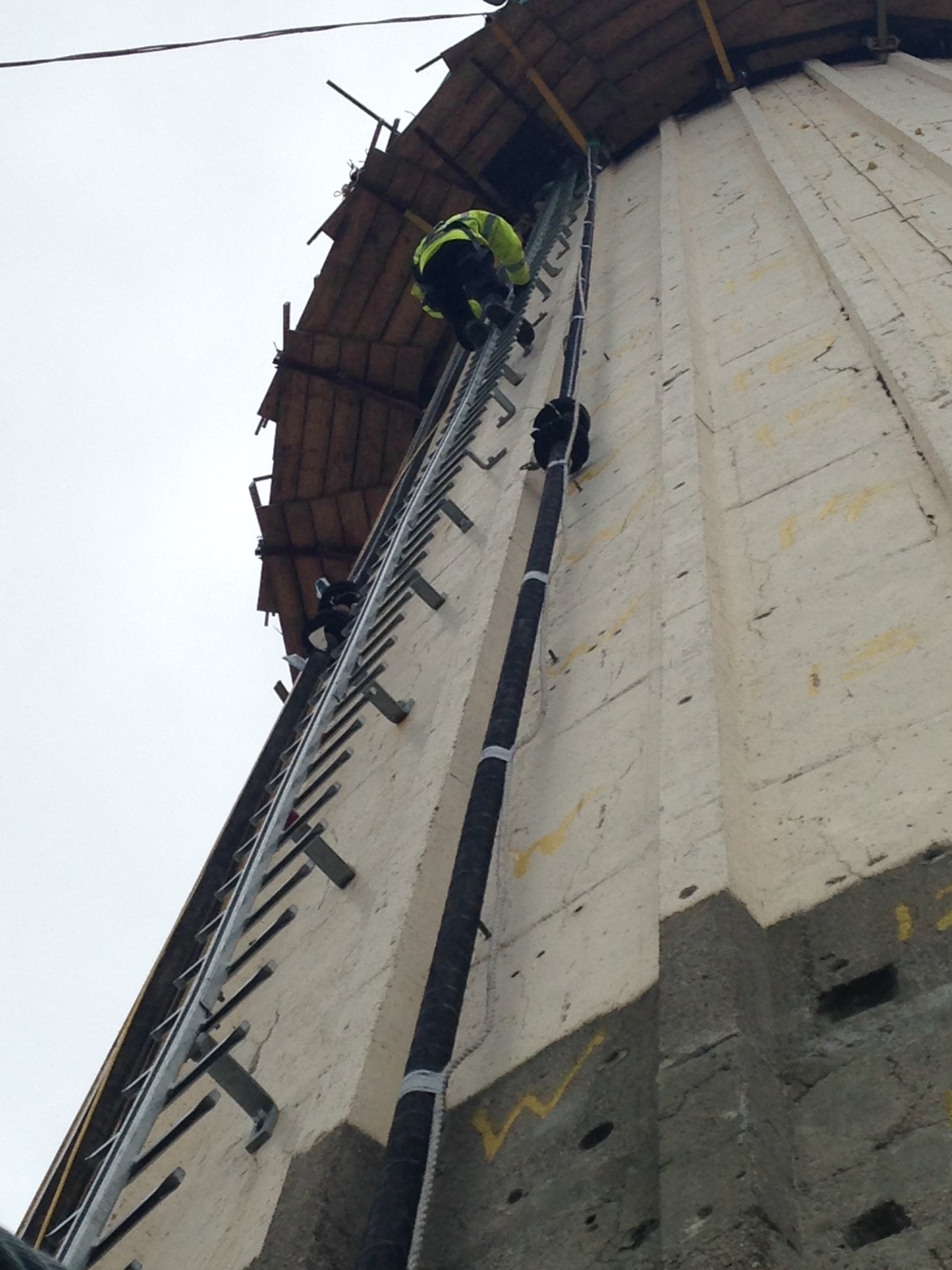

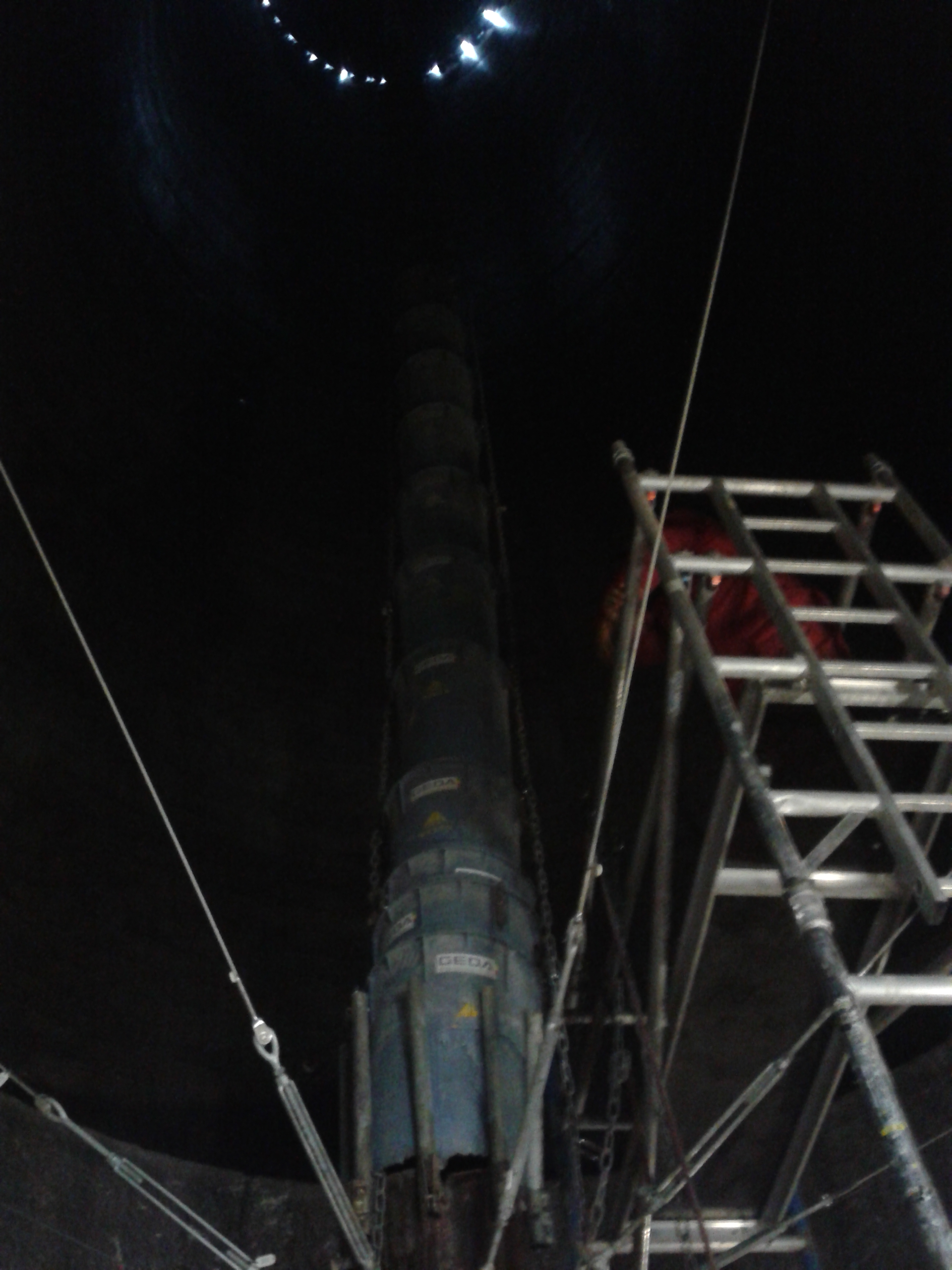
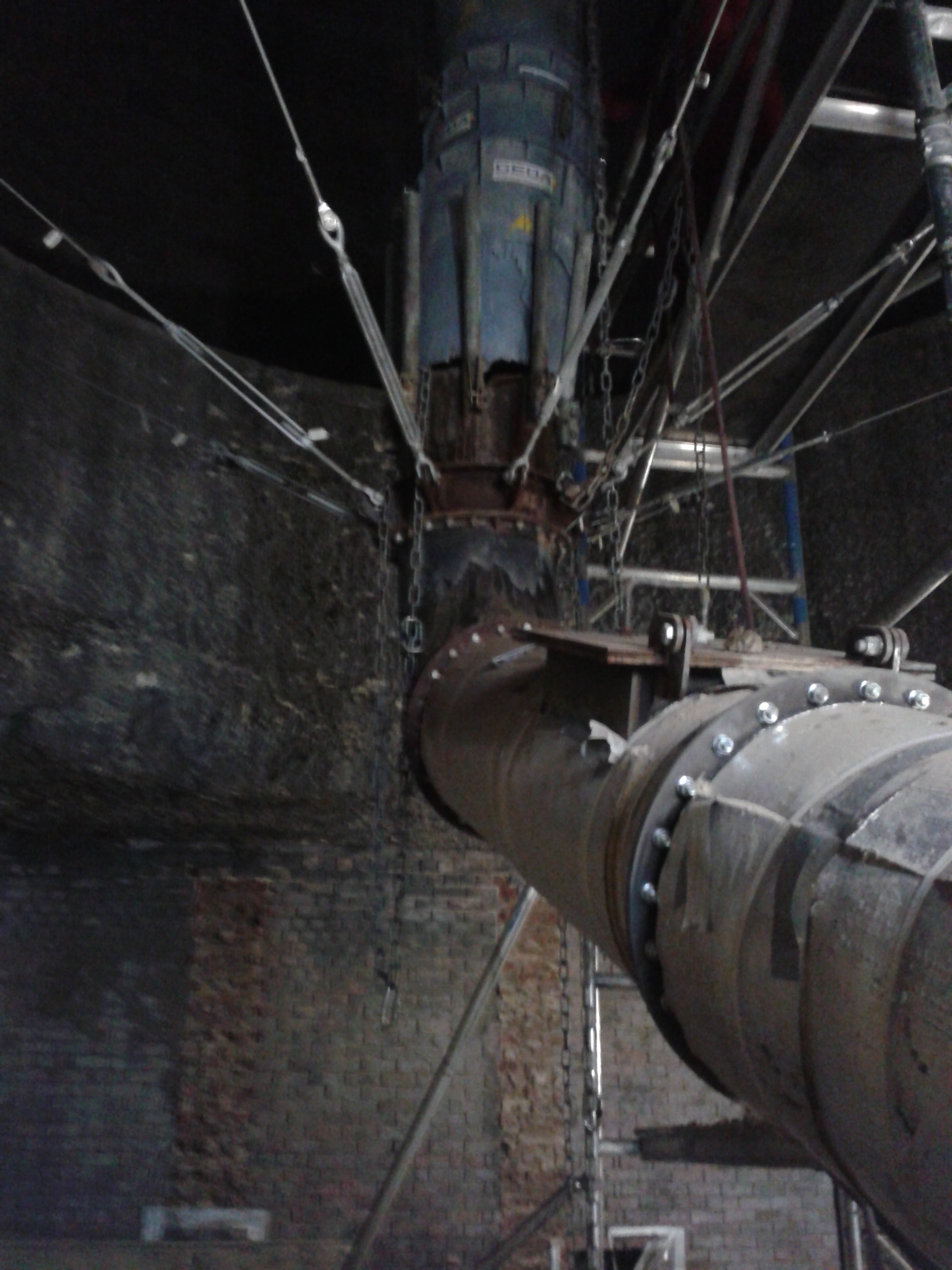
At the top of the chimney they have two circular platforms which can ‘climb’ up and down the chimney using hydraulic actuators on the bottom platform. They act as compressive bands around the chimney providing support keeping the concrete in compression. Hoists and other access methods were not used as vibration and differential loading could cause the 80 year old concrete to continue to crack and spall. Prior to the breaking of the concrete the interior of the chimneys was sprayed with a sealant to prevent the tiles which line each chimney falling off and to seal in any contaminated particles. The original plan was to use hydrualic concrete breakers on Davit arms on the top platform to crush the concrete and the reinforcement was to be cut using hand tools. The broken pieces were caught in the centre of the chimney in a collection funnel which then travelled down the centre of the chimney into the building. The pictures below show: 1) the breakers, 2) the chimney rebar, tiles inside the chimney and top of the collection funnel, 3+4) the funnel chute inside the chimney.

The dense lattice reinforcement meant that the breakers did not work effectively and the concrete did not separate from the rebar easily. The process was proving to be too slow so they switched to using pneumatic hand breakers and circular saws to break the concrete and cut the rebar. The process is quicker but more operatives are required due to the time limitations on the equipment due to the risk of HAVS.
The chimney will be demolished until the final section where the client want to keep a full section for display. It is yet to be decided how this will be achieved! The chimney will then be rebuilt using the jump form technique in 1.2m (4ft) sections to achieve the same ‘day lines’ as the original chimneys. The paint has already been matched and a small concrete batching plant inside the building will be used to produce their own concrete. Once they have built 25m of the first chimney, they will have the planning permission to continue with all 3 of the other chimneys concurrently as the cost and methodology will be proven. They are already looking into other forms of mechanical breaking rigs for use on the other chimneys to speed up the process and reduce the use of hand held equipment.
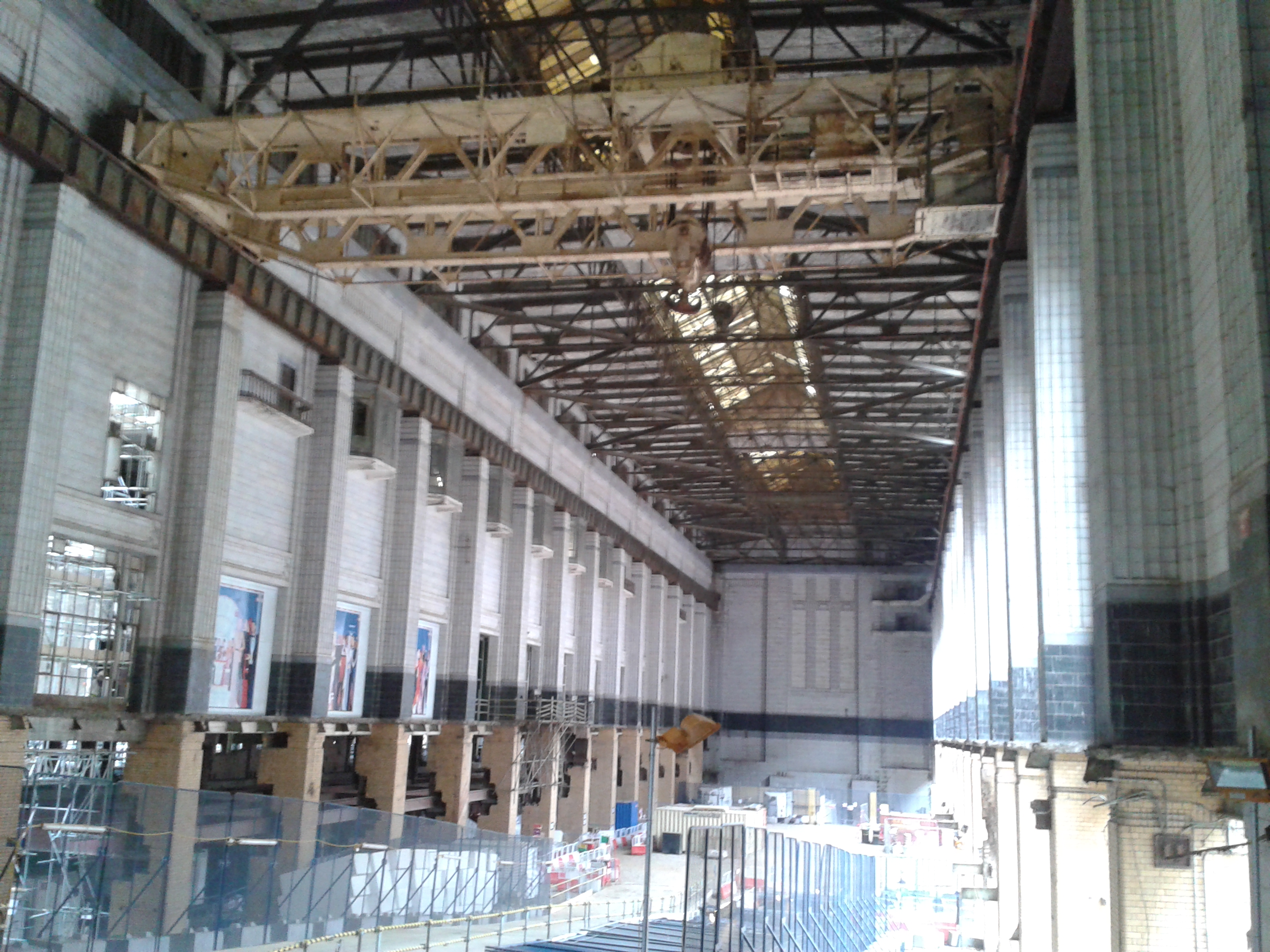
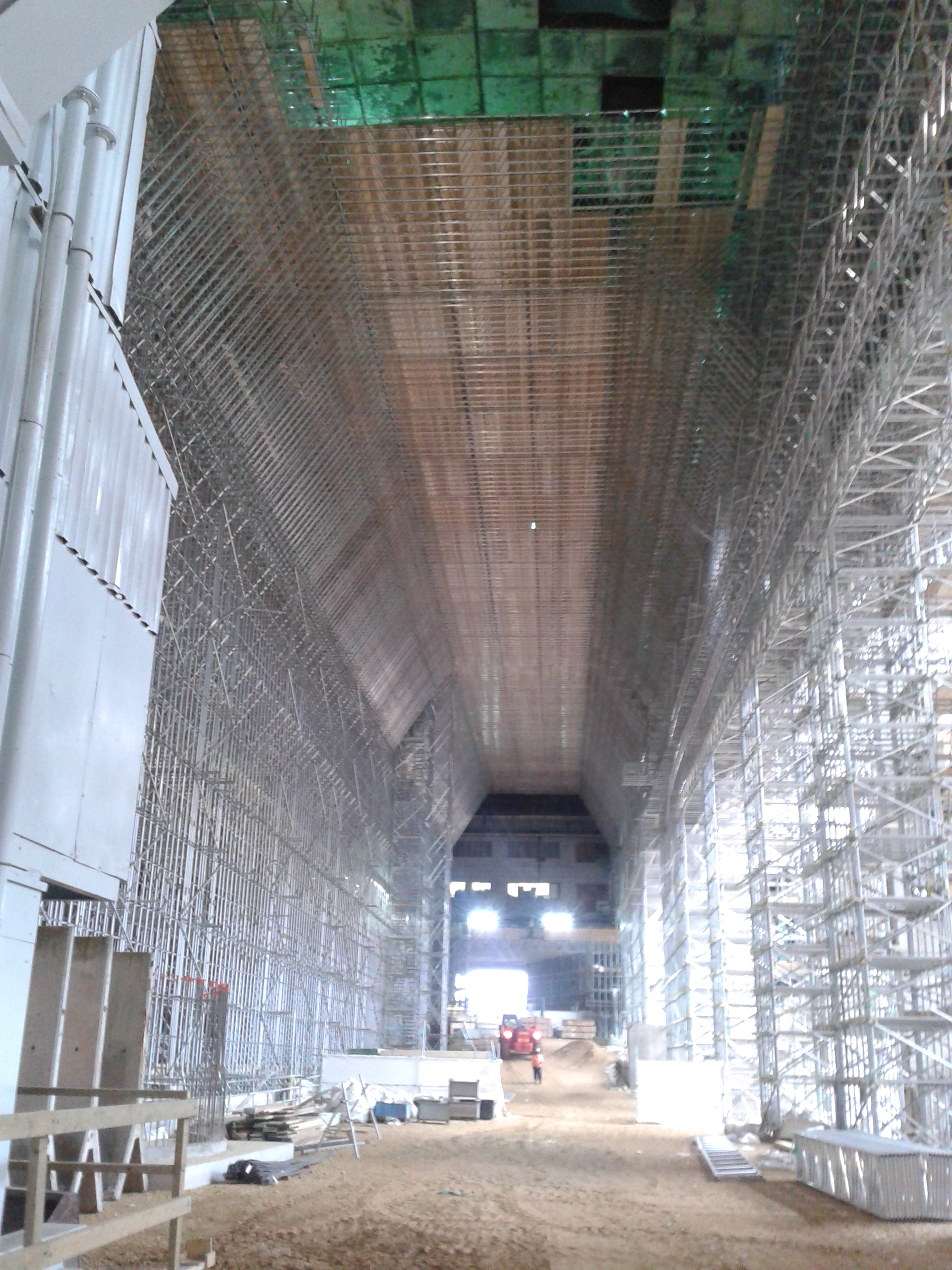
I was also shown around the main turbine halls which will be being refurbished. The asbestos has been removed and work has started on erecting the scaffolding to repair the roof. Even that is an impressive structure that I would not like to do the temporary works design on!
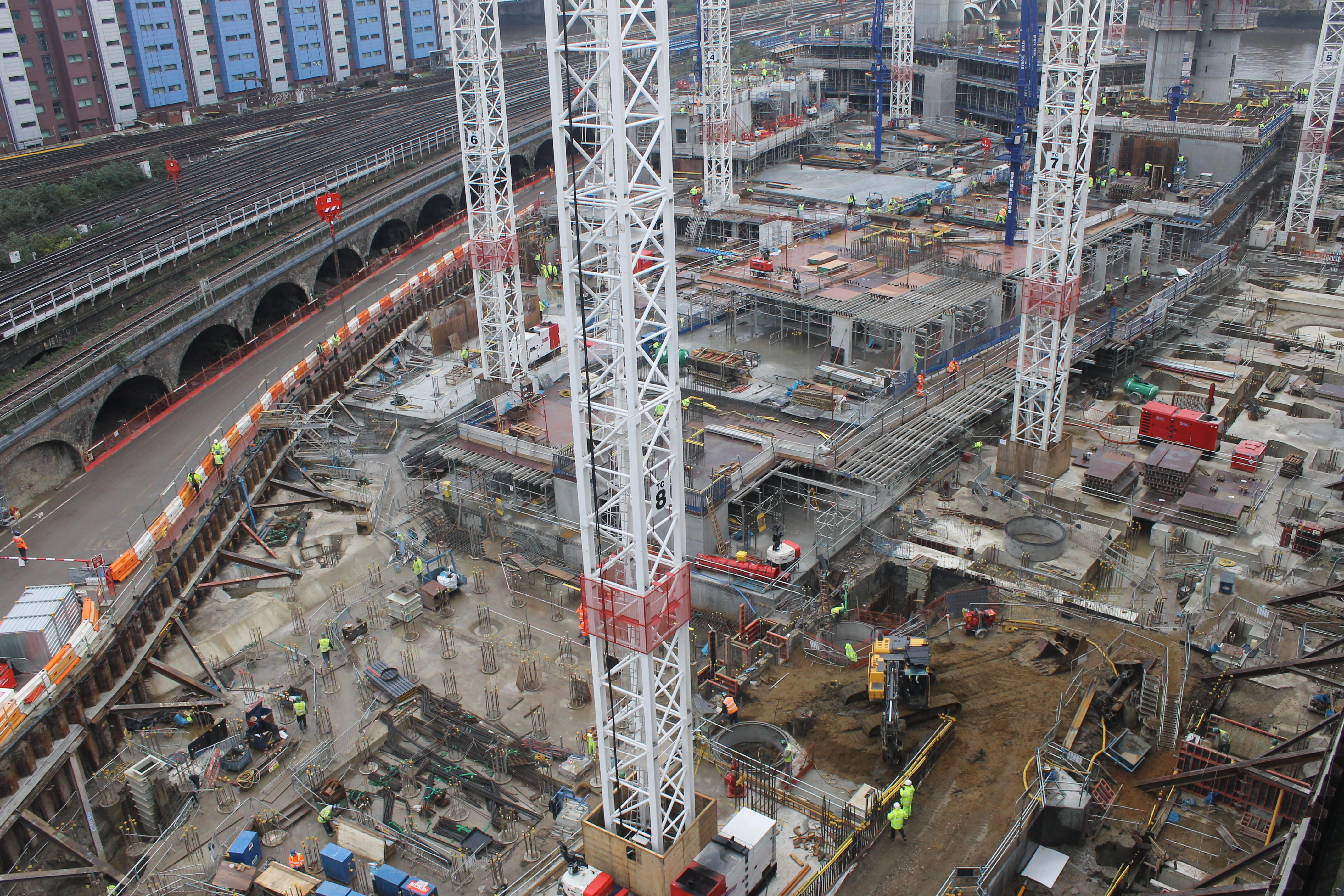
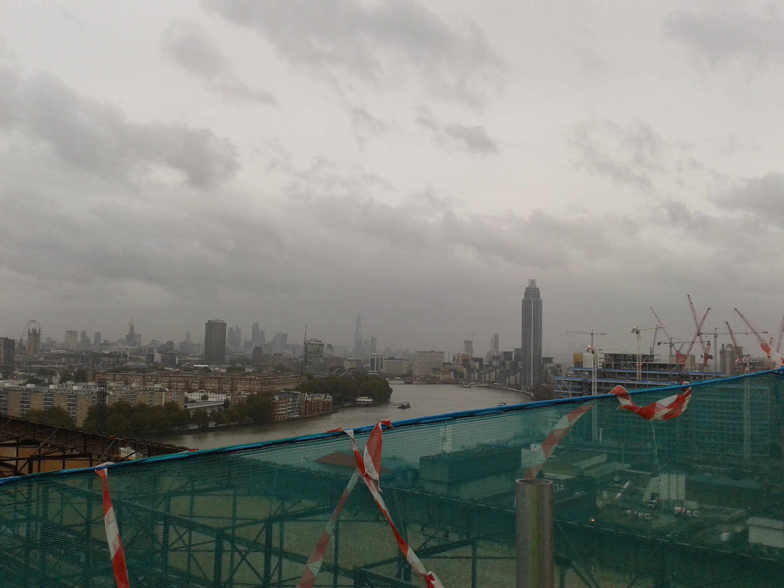
The trip up the chimneys also provided a good vantage point to view our construction site with Block G looking like Ex Cofferdam and my Network Rail Road standing proud along the main site.

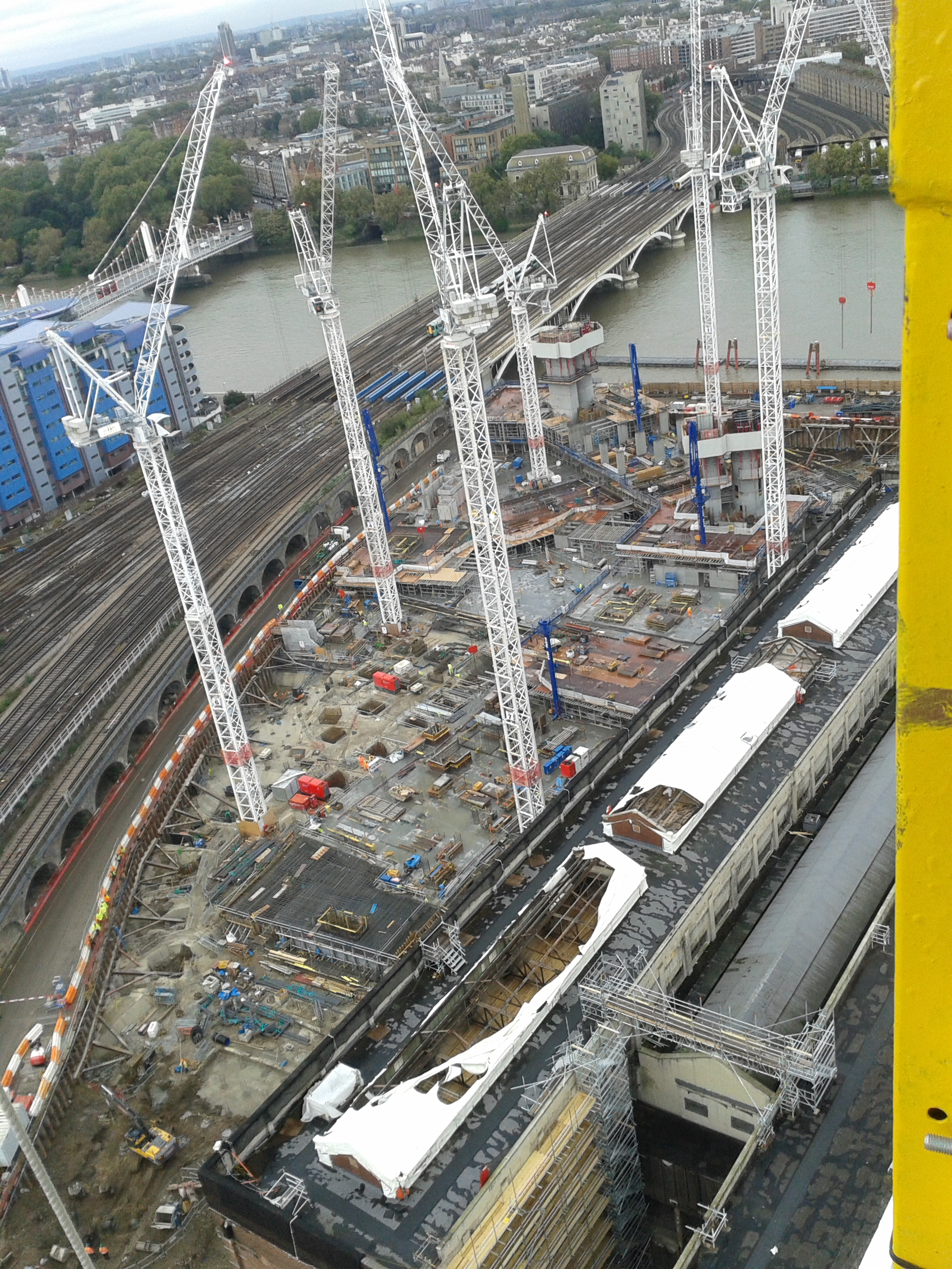
Back to the real world and my construction site. Well we hit a major milestone with the HV being switched on the other week-only 6 months later than planned! We are also near to getting the approvals for the microboring so work is likely to commence in the next couple of weeks. We also found out today that the Northern Line Extension contract has been signed by Laing O’Rourke and they have designed their escalator shaft to go straight through our HV cables, water supply and comms ducts despite them being a constraints drawing showing them! I think this project will be trying to dig up as much of the previous phases as they can as co-ordinated design doesn’t seem to be their strong point!
Block G Catastophe
Well I escaped the responsibility of Block G as there is still plenty of work to with ensuring that everything gets completed as OIC sewers, water and power. But I thought I would blog about this event from a few weeks ago especially for John and the Phase 1s as this is the part of the cofferdam they might be visiting.
Background
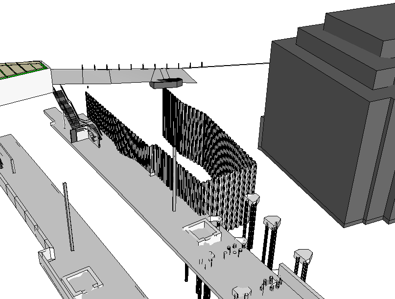
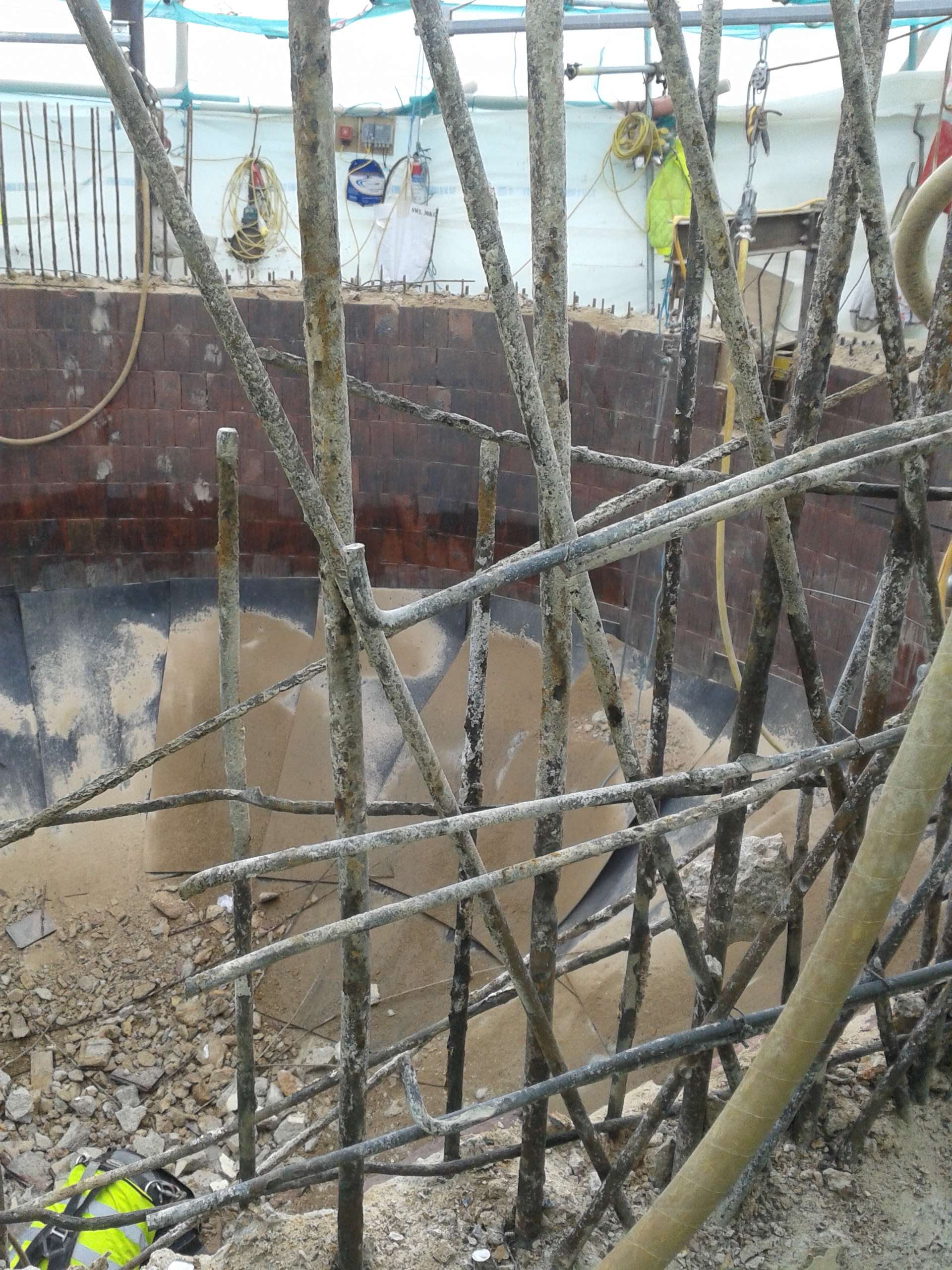
Block G is the most southern section of the building about 25m from the SW corner of the power station. On the thinnest part of land between the building and the railway arches. It is also the deepest part of the basement with the excavation due to be taken down to 8m BGL.
 Block G (Power Station is to the top-left (25m) and railway structure below the drawing (10m))
Problem
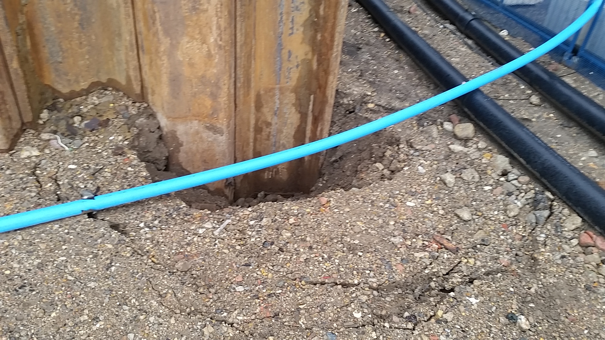
As the dig was progressing the banksman noticed a hole in the sheet about 200mm by 200-250mm located at around -2.3m to -2.5m AOD (Ground level is +3.5m AOD). The hole seemed to have had a plate welded over it but the plate had come off. With the ground water level at around 0m AOD so some water was coming in and we had a bit of a puddle forming at the bottom corner.

Initially that morning all were very calm, just a bit annoyed that there was a hole in the sheet pile. Apparently the hole had been noticed over the weekend but it wasn’t until the rain on Bank Holiday Monday that the water had risen to 1m high. THe construction staff in the office started to fly a few ideas around about how to seal the hole but with unstable sandy gravels and some clay in the excavation is wasn’t a safe enough surface to work from.
By 1600 hours after more rain things got more interesting and a nice pond feature started to appear:


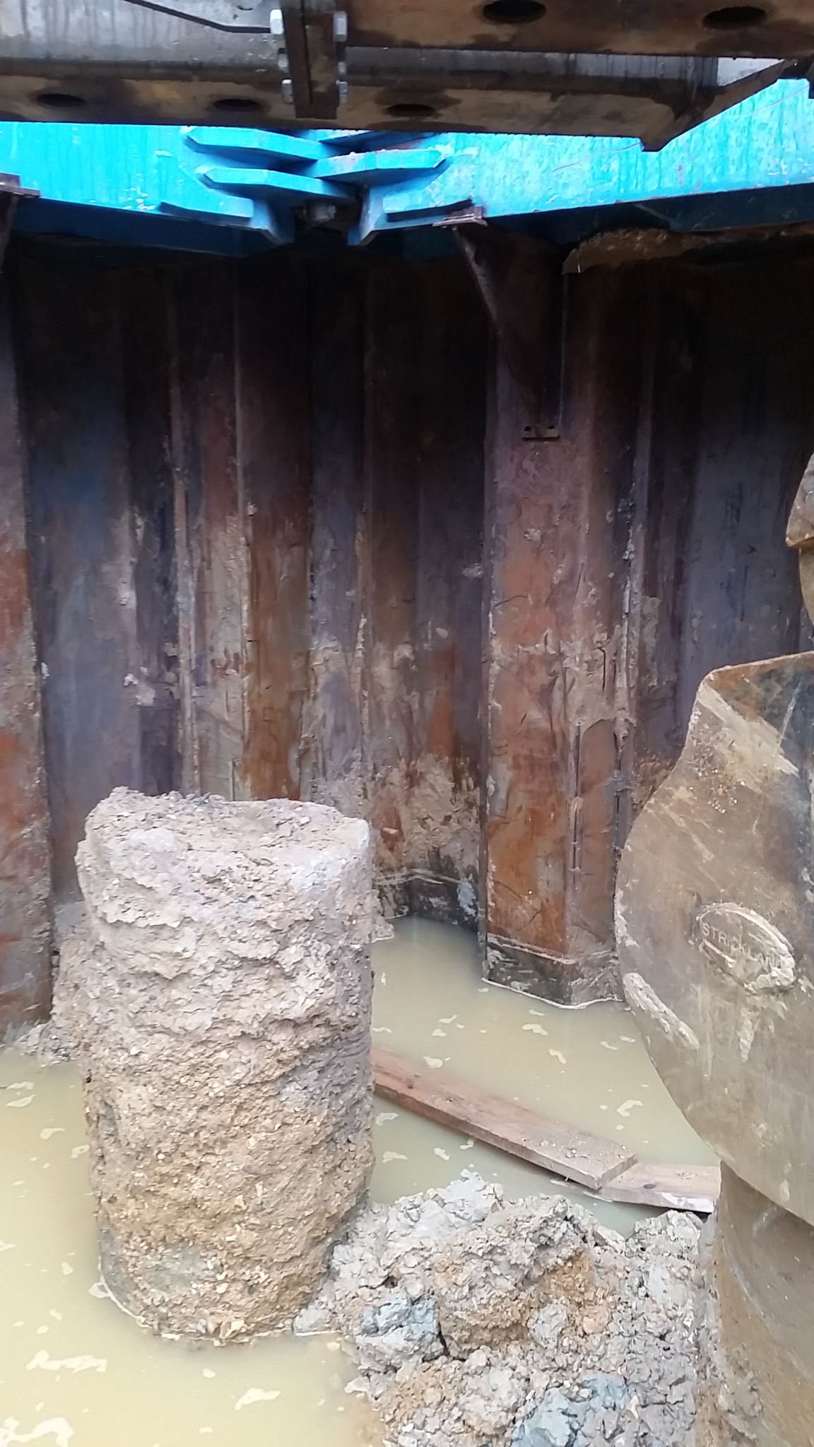
The excavators had retreated to the highest points they could but the water had risen nearly 1.5m and was now lapping around their tracks. The office then became much more excited and frantic emails were being sent backwards and forwards between the construction manager and the temporary works department. The de-watering well can be seen in the pictures as the blue vertical pipe and this was maintaining the water level but not draining it. They tried to pump the water out with 2 tankers but the high groundwater levels in the terrace gravels above the clay layer just kept coming in. They then noticed another problem hiding behind the sheet piles:
The constant pumping and removal of the water was also washing the fines into the hole creating voids causing ground loss on the surface behind the sheet piles. Luckily this corner isn’t right next to the power station or the railway line!
Solutions
My input to the problem was the suggestion of whacky ideas that could actually work the best being what I learnt on the Royal Navy Damage Repair Instructional Unit:
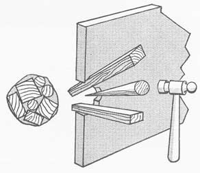
All you needed was to get the water down low enough to hammer some soft wood wedges in the hole or get a diver in! But since we couldn’t get the water levels down enough and a diver would take far too long the idea was liked in theory but not in practice.
The only other option was to block the other side of the sheet pile by driving another sheet pile behind it. All pumping was stopped to allow the water level to equalise and stop the migration of fines and they set about building a piling mat to support the crane required to drive the sheet pile into place. Once completed the water was pumped out and the culprit was uncovered and a plate was welded over the hole:

Lessons Learnt
- Don’t scrimp on second hand sheet piles at the deepest part of the excavation!
- Don’t use sheet piles with holes in or a plate welded on over the hole as they get ripped off during driving!
- If there’s a hole in your sheet pile, plug it immediately, don’t wait for it to flood over the Bank Holiday.
- Pumping water out of an excavation being fed by a months rainwater in the ground probably won’t work.
- RE Divers would have probably fixed it in a day and actually earned their dive pay.
Conclusion
Having caused a 1 week delay on the progress of Block G and incurred the cost of an additional piling mat and sheet pile being driven it will be interesting to see who foots the bill for this one. Carillion will blame the sheet pilers for using defective piles. They will blame Carillion for telling them to use second hand piles (one story is that decision was made to save money as these piles will be cut to join onto the Phase 2 works, the other story is that the job was rushed and only second hand piles were available). Someone will no doubt get the task of digging through numerous Employers Requirements (ERs), Addendum ER and Contractor Proposals to point the finger of blame.
Extra-Curricular Work
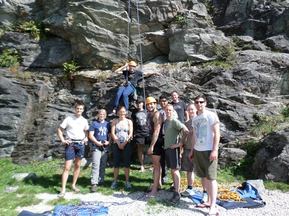
One of the reasons that Neil thought I was dead was that I have been away for a week in France teaching the AAC how to climb. I successfully delivered the new Rock Climbing Single Pitch Foundation (RSF) Course to 8 students on their expedition to a small place just outside Chamonix.

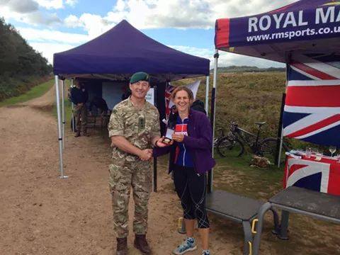
In the last month I have also become the Army Female Mountain Bike Champion and I represented the Army at the Inter-Services yesterday where I became the Inter-Services Champion. Unfortunately as a team we were beaten by the RNRM (who had set a gnarly course that looked like a B3 had got lost in the woods with a piece of mine tape!). I am hoping to race for the Army in National competitions next year and also get a nice bike sponsorship deal (and yes Rich, I am becoming a Stravasshole!).
The pipe-jacking saga continues…
I tried to post this before my holiday, but it seems that WordPress and I don’t get on that well so here I go again 4th time lucky!!
Well this is my 3rd attempt at a blog as first my computer turned itself off then the site crashed whilst trying to save my work. I am off on holiday in 1 hour so I will be quick!
For the last 6 weeks I having been waiting to be able to write a great blog about pipe-jacking under Battersea Park Road with pictures of the launch shaft or some pipes going in. But alas no, we are now going back to looking at different methods because it is too expensive. To cut a long story short the client’s representatives (T&T) and client (BPSDC) nearly had a fit when the £75k provisional sum wouldn’t even cover the launch shaft. Due to the soil type (Terrace Gravels) and water table above the pipe-level, the costs have escalated to £960k! Cue lots of panic and many meetings questioning how on earth it had become so expensive. Here’s why:
Due to the likelihood of hitting an obstruction under Battersea Park Road Bridge the open-face pipe-jacking technique was decided using a 1.2m diameter ID pipe allow miners to excavate inside. Due to the groundwater, this would require de-watering along the full length. As the bridge covered half of the 75m the de-watering regime would not be able to achieve such a large radius of influence without potentially affecting the railway lines 10m from the pipe. Therefore resin grouting would be required for the last 35m. So what was once around £250k for the pipe-jacking alone ballooned to nearly £1m once you looked into the detail design.
Despite my best efforts to explain this with the sub-contractor T&T looked at alternative solutions such as micro-boring and a representative from Barhale came along with his sales pitch. He tried to say that pipe-jacking with miners over 25m went against HSE guidelines (our H&S person then dispelled this as it is allowed with safe systems of work in place). He then said that micro-boring would save lots of money as de-watering and resin grouting would not be required. T&T thought that this was the golden chalice and they put a halt on all pipe-jacking work and made us investigate this more. Since we had already done this exercise back in March less the pricing side of things it wasn’t too difficult to highlight the constraints for the micro-boring. The big ones being: if it hits a boulder over 1/3 the size of the pipe, or timber or steel, it gets stuck-a cost of £350-500k and still no pipe under the bridge with no back-up plan. If that wasn’t enough to put you off then the installation of the reception shaft would need to be in a public cul-de-sac over the trunk main. Diverting services and digging up the street is also not a cheap option. A representative from Terra another tunnelling company also came in to explain this and suddenly T&T’s golden chalice turned into a poisoned one (and I refrained from shouting “told you so!!”). Now we will not get the job done by our deadline of the end of the year when the Northern Line Extension starts at the south of the site in Jan.
So it looks like we will be back to pipe-jacking when they make their mind up this week and I have left the 200 pages of Risk Assessment and Method Statements and temporary works designs with Network Rail for approval. Now I am off to Turkey kite-surfing for a week so next week should be quite interesting!
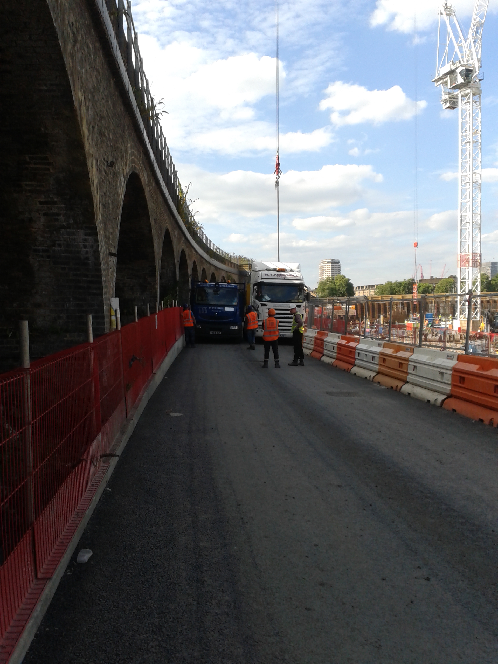
The Network Rail Road not so grand opening
Well the Network Rail Road was meant to open on the 26th Apr but due to various issues that I will go into a bit later that did not happen and only a small portion was opened. Grand opening number two was the 30th Jun and I hoped to write a great blog with pictures of us all celebrating a milestone, but 2 weeks later we are still not finished. So why has such a simple task of building an access road been so difficult I hear you all ask. Let me explain…
Here is what was explained to me back in Feb:
Mission: To construct the Network Rail Access Road once all services have been installed.
Concept of Operations
Intent: To open the Network Rail Road for construction traffic.
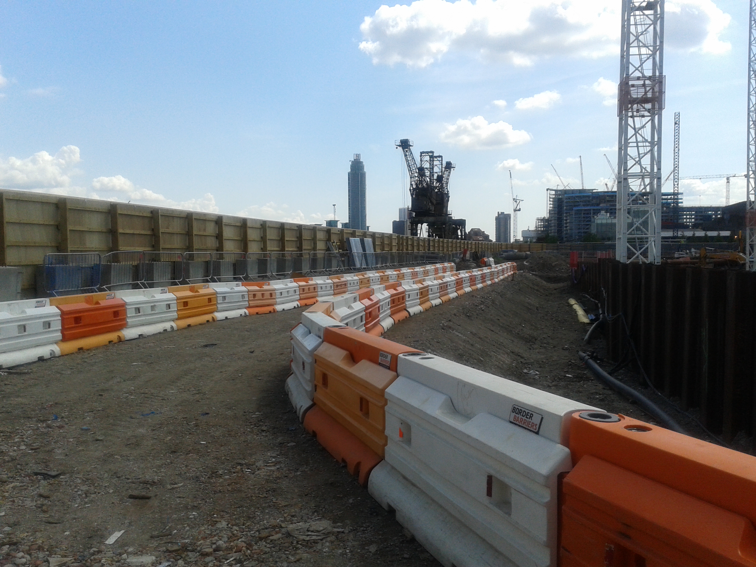
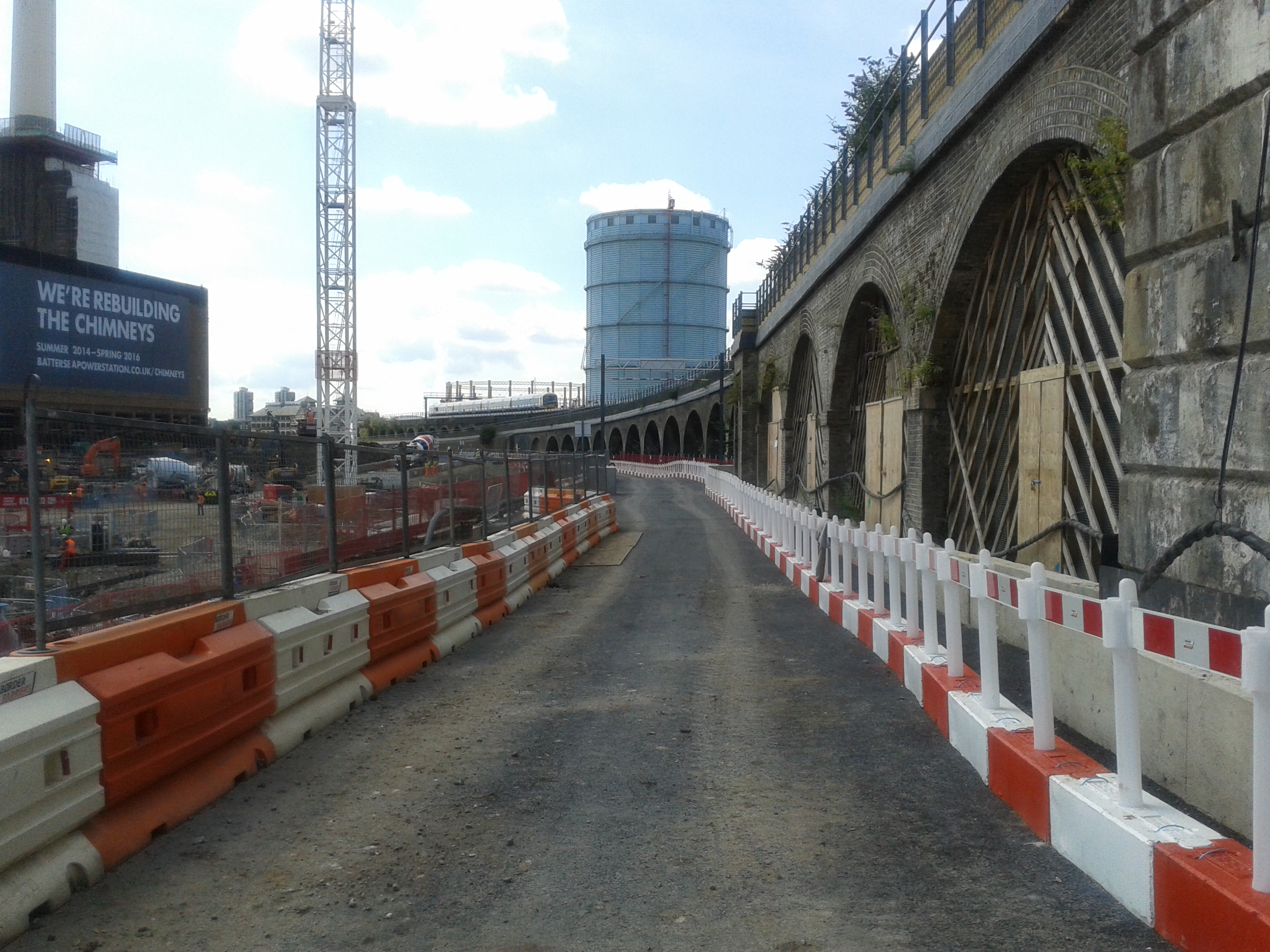
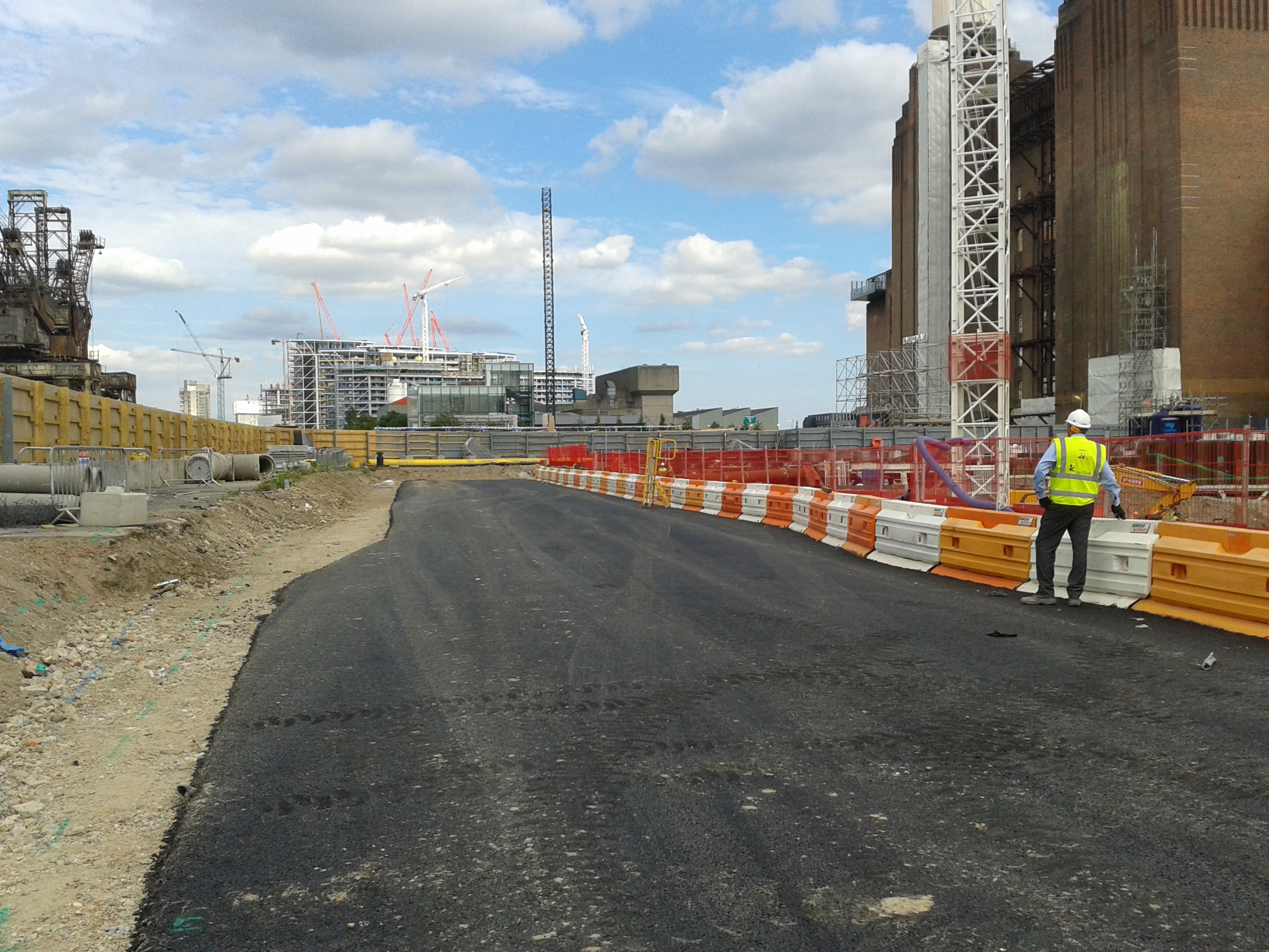
Scheme of Manoeuvre: Install deep foul drainage, then surface water drainage, followed by shallow services such as HV, potable water, rising main and comms, install the final road build up and surface. The diagram below highlights the main locations with the road running along the left side of the picture.

Main Effort: To open the road for construction traffic use by 26 Apr.
Constraints: The road is bounded by the Network Rail arches (the main line into Victoria) in the West, the sheet pile cofferdam of the basement in the East and the River Wall to the North.
Again it all sounded pretty straightforward, the sub-contractor had a realistic looking programme and they had already made good headway on part of the deep drainage when I turned up in Feb. So what has gone wrong?
Issue 1. The major problem has been a temporary works issue that arose from a contractual decision. The capping beam of the sheet pile cofferdam for the basement was originally in the groundworks sub-contractors (O’Keefe) package but as a cost saving effort it was taken out and put into the concrete frame sub-contractors scope (Byrne Brothers). With the contractual team happy in the thought that they had saved a few pennies the construction team carried on building. It then became apparent at the start of March that we kind of needed the capping beam to hold up the road that we were building and now the contractor had changed it wasn’t going to be built for a few more months.
Solution: To cut a long story short we ended up getting O’Keefe to design a temporary retaining wall for the road to allow the construction of the road and the formation of the capping beam. This was in the form of a king post wall made from UCs and trench sheeting and pre-cast L-sections (my idea stolen from John’s retaining wall lectures!). The pre-cast sections were suitable for south of the pumping station where they would fit in with the services but not for the north. These were installed quite quickly and the south section of road was opened on the 26th Apr as planned. The king post wall installation added another 6 weeks and probably 10’s of thousands of pounds to the cost of the groundworks package.
Issue 2: The road level was designed to give enough cover for the shallowest main service which was the rising main. The Project Director wanted as many of the smaller branch connections to supply the bridge arches (mostly clay drainage pipes) in as possible prior to the surfacing of the road. Once constructed it was apparent that these were not going to have enough cover under the road.
Solution: Ramp over them, chuck some trench plates over the top and hope they don’t get trashed!
Issue 3: Nobody had actually designed the northern section of the road. The design engineers Buro Happold had helped with the suggested temporary levels of the main part of the road and this was signed off by the Carillion Temp Works Designer (TWD) (who doesn’t work on site or solely on this project).
Solution: The Carillion Project Manager suggested an idea to the TWD, he said no, we amended the design to his comments, the Environment Agency Flood Defence Consent people said yes so we cracked on and built it.
Issue 4: On the grand opening take 2 on the 30th Jun the Project Director walked the road with Byrne Brothers (who will be the main user) and they deemed it was not fit for purpose. Despite being built to the designs it was both not wide enough (for 2 way traffic) and too wide (not enough room to construct the capping beam). They had intended to have unloading areas for the tower cranes and vehicles passing at numerous points along the road.
Solution: Remove the pedestrian walkway, push the vehicle barriers closer to the edge, make it wider in the north (ignoring the design of one TWD and using another ones design that allowed for more surcharge on the sheet piles) and hold your breath and close your eyes as your truck squeezes past the artic lorry:
So what have I learnt from this rather frustrating and costly ordeal?
Communication is key. The section engineer in charge of Byrne Brothers is too busy to attend construction team meetings and therefore has never communicated the actual intended use of the road. If the sub-contractor and I were told that they intended to unload vehicles then we could have flagged up the width issue months ago. We could have also planned the barrier system to ensure the widths were adequate rather than build everything then strip it out again.
Plans should be war gamed. The decision to remove the capping beam installation from the groundworks package has significantly affected the road construction. Changes to the plan should be communicated and discussed with everyone that it may affect so problems can be identified early.
Have a clear reporting chain. Too many people have been involved in making rushed and ill-informed decisions with regards to the road and nobody has been the single point of contact in charge of it’s construction. I was given the responsibility of monitoring the installation but it became apparent that I had not be told the end user’s actual requirements. Decisions were made by the Construction Manager that then didn’t work on site and he should have delegated the responsibility of designing a solution to me or one of the other section engineers who work frequently on the site. We could then brief potential solutions to allow the senior management to make an informed decision.
Well tomorrow I get to draw up the second sketch of remedial works and hopefully some white line loading bays will get painted on the road on Sat and I can have the grand opening take 3 on Mon. In the mean time I will be trying to help design an elevated footpath to help widen the road some more! I think a more detailed (and slightly less sarcastic) analysis of these technical and managerial issues associated with the Network Rail Road could be the next TMR topic for me.
All trains from Victoria CANCELLED…….
Well today I was in my element utilising my military skills and my search advisor knowledge! It involved 5 police cars, 3 fire engines, an ambulance, the evacuation of the site, closure of Battersea Heliport and all train lines coming from Victoria. At around 1430 Hrs one of the engineers came up to the office saying that the piling rig had dug something up that could be UXO. Being the only person that vaguely knew one end of a bomb from the other I agreed to go and give my expert guestimate of whether we should be running for cover.
On arriving at the piling rig I found this:
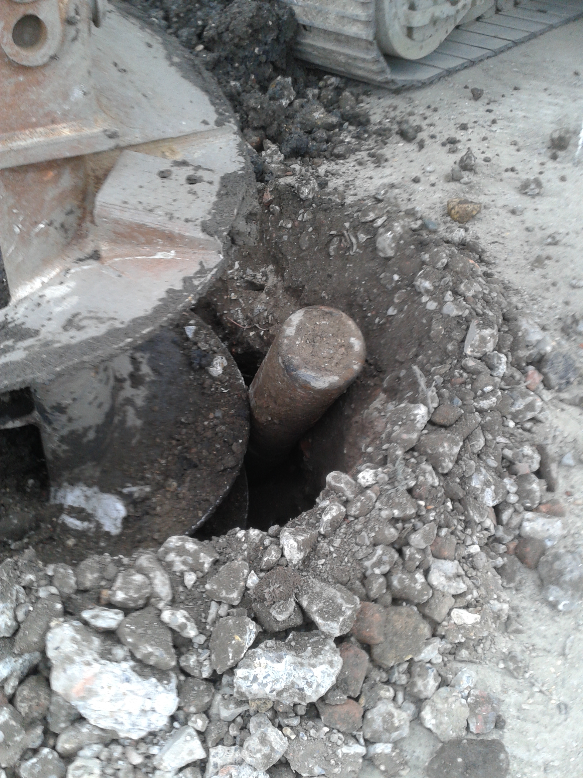
It was around 150mm diameter all the way down with no tail fins or pointy ends so I was 90% sure it wasn’t going to start ticking at us. I took some photos to brief the services and then cleared my area of responsibility of operatives. As the site was getting evacuated I found the piling rig operators and used the search advisor questioning technique to find out what they were doing when they found it and what actually happened. The rig was drilling the pre-bore for the casing when it hit a metal obstruction about 1.5m BGL. On moving the auger forwards and up, it uncovered the metal object that started hissing. At that point the rig crew stopped work and promptly left the area to raise the concern. We got the site evacuated and after around 45 minutes 4 police cars turned up.
I ended up briefing the police and showing the photos with the senior construction manager and an ex-RE policeman went down to have a look. He confirmed our suspicions that is was more likely to be an oxygen or acetylene cylinder and the police decided to establish a 400m cordon. With the train lines around 30m away and the cylinder pointing straight at them and the flats the other side of them-all the trains from Victoria were cancelled and the flats started to be evacuated. Finally the fire brigade turned up and I had my briefing map and photos ready. It reminded me of the old 4Cs operation we got taught on PDT for Iraq. After seeing the photos they reduced the exclusion zone to 200m and they sent some guys with breathing apparatus to go and check it out despite the fact we had been stood next to it over an hour before!
To cut a long story short, they confirmed what we had told them and went with the construction manager’s plan of attaching some strops to it to support it and reversing the auger to lift it from the hole. Low and behold it worked without going bang and everyone went home for tea and medals and the trains set off again.
Here’s the culprit:
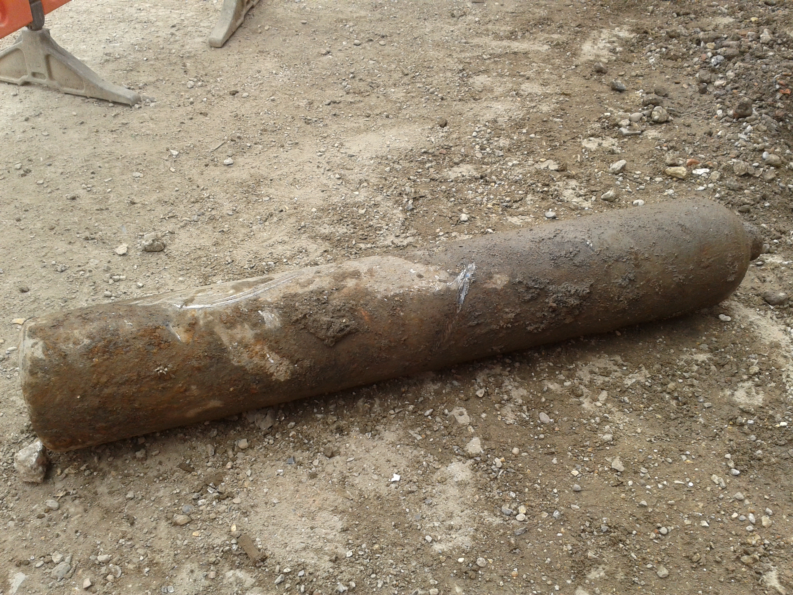
We are not sure exactly where it came from but it looks like it was between our pile mat and another piece of terram. It may have been buried during the backfilling of a previous dig or development prior to us being on site. It is likely to throw up a whole world of debate about whether excavation and piling on the site is safe as if they had struck the cylinder straight on it could have exploded. It will also be interesting to see whether the client ends up footing a bill for the closure of the railway line or whether incidents like this outside our control are excluded. One thing I will be implementing on site is a proper laminated briefing map and some advice on how to control incidents. I was amazed with how many people rushed to take the afternoon off, leaving a couple of people to deal with everything. Even the police and fire brigade didn’t really seem to take command and control as I would have expected them to do. I am more institutionalised than I thought!
Cakes and Pipe Jacking
I have been rather quiet as I realised that all I seemed to be writing about was what size cast iron pipe we unexpectedly uncovered on our drainage run and what was going on with the latest in the HV cable installation saga. Well nothing has changed there we are on big old cast iron pipe number 6 in the last 10m of drainage, the client are getting excited about us damaging the HV cables and we are now extended the HV sub station slab because they put the wrong size GRP housing on top of it.
At the end of last week we had a team meeting to discuss roles and responsibilities as the Project Director has realised that they may have scrimped too much on construction management staff. We have no resident temporary works engineer or quality assurance person and these are the areas that the project are crashing and burning. At the start of the week I was looking at a promotion to being the resident engineer of the block G construction-think Ex COFFERDAM but 40m wide and 100m long with 2 stages of propping! In the initial meeting I pointed out that they might want to consider the detail of the connection of the waler to the sheet piling as they were suggesting a 1m gap to allow the construction of columns. They said not to worry about it as they would use wedges, until I pointed out that wedges spanning 1m taking vertical components of the forces probably wouldn’t work! So they went back to the drawing board and asked to move the columns in a bit!
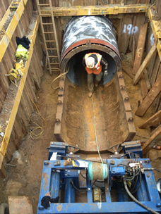
OIC Power and Drains again! But this is taking an interesting step as we are planning our pipe jacking exercise to tunnel under Battersea Park Road. In a nutshell the masterplan is to build a cofferdam to launch the pipe jacking machinery to cut a 70m tunnel approx 5m BGL to meet with an existing sewer on the other side of Battersea Park Road. watering scheme.
Pipe jacking launch shaft in top left corner tunnelling 68m with the final 30m under a raised section of the Battersea Park Road bridge: and a typical pipe jacking launch shaft:

General works:
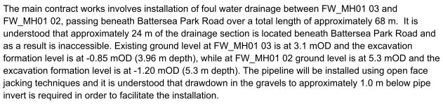
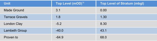
The main issue is one of John’s favourites: GROUNDWATER! In the foul drainage run we have had to sump pump a considerable amount of water flowing through the Terrace Gravels, which is also slightly tidal as we are about 300m away from the river.
![]()
The plan is to control the groundwater with a de-watering system:
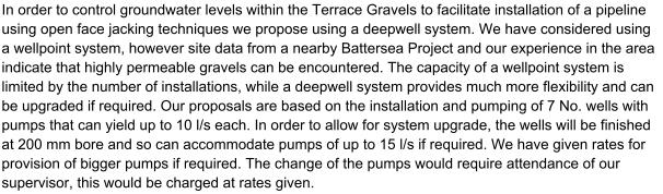
Likely issues:
-Proximity and state of dilapidation of the Battersea Park Road Bridge.
-Proximity of Network Rail lines.
-Risk of settlement of bridge foundations.
-Risk of encountering unknown services or obstructions.
-BOUNDARIES/PROPERTIES-although we can’t be tunnelling through much worse than the gravels which will be pouring water in! Unless we hit an old brick pile or more of the old gas works infrastructure.
-GROUNDWATER-we are pretty much in the worst case scenario.
-CONTAMINATION-So far we have been OK with de-watering around the site so fingers crossed it can just go down the foul sewer.
Without looking at my notes they were the main points I remember from John banging his hand against the wall! No doubt I will have more to write on this over the next few weeks.
On a plus point I held a Colossal Cake Sale for Help for Heroes in the canteen and we made £220. I mentioned to our Environment/Schools/PR person that I could come in uniform and she held me to that offer. The problem was mine was all in the attic in Poole. So after a quick cycle to a friend’s house 5 miles away I squeezed myself into an ex-Army Air Corps Adjutant’s tailored(!) green kit to sell our cakes for an hour. I was overwhelmed by the generosity of some of the guys on site and the support from both the managerial staff and groundworkers. Not a bad outcome for a couple of hours work.

