Archive
Who has the force?
I am currently designing a turning dolphin for a tideway project in the Boston Barrier area. The dolphin will consist of steel tubular piles driven into the river bed with a 2m deep RC pile cap. The cap will have a bollard fixed for mooring ships. The dolphin will also require fendering.
Fendering forces (for those that don’t know) are calculated from the berthing energy being dissipated over distance and time. This means that you can only calculate a “fendering force” once the fender has been chosen.
The problem has arisen when deciding the forces on the dolphin. It is BAM Nuttall’s opinion that we should be provided with the forces to expect from mooring and fendering and design a structure to resist those forces. The client has paid for a navsim analysis of the shipping externally and they have provided a line force (fendering) and point load (mooring) for the structure with a caveat that these numbers should be used to validate our own and not be used as a design value. These simulations and calculations were executed with assumed fendering choices and are therefore not really worth the paper they’re written on.
The elephant in the room is nobody thinks it’s their responsibility to provide the fendering solution and nobody wants to stick their neck out and offer up a design value. In our eyes this is a dispute between the client and HR Wallingford but we are caught in the middle. If the client isn’t paying Wallingford to provide us with these forces then why are they paying them? When BAM bid for the design, they did not include the cost of calculating these forces into our quote. This means if we are stuck with having to do it we will need to subcontract this out (as we do not hold the specialty within the department) and will not be able to recover the cost.
As I have no view of the contracts between each party I am simply an outside observer speculating on what disputes may arise from this project. I thought it was an interesting question to ask though about where design responsibility for determining forces lies. Of course we would assume responsibility for calculating wind forces on a hoarding so why not fendering on a dolphin?
Friction connection?
This is interesting. I’m checking a design for a temporary concrete retaining wall. The wall itself is simple enough but the connection is something I haven’t come across.
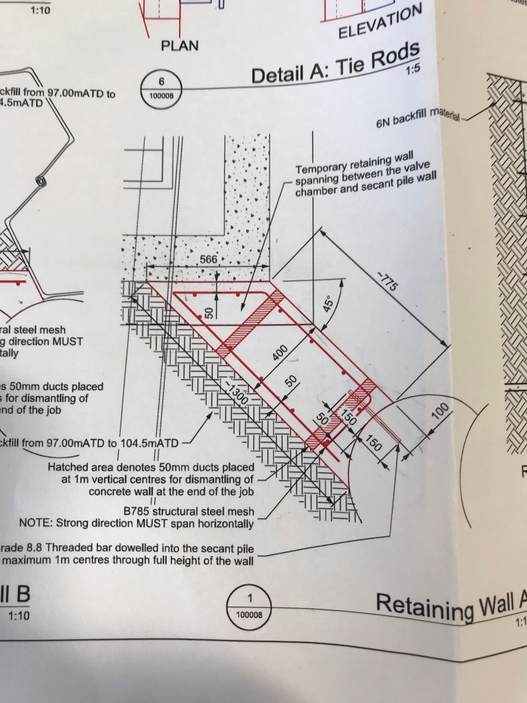
The wall is being held in place with a threaded bar on the right and “friction with the existing wall” on the left. So the designer has said that the angle between the retaining wall and existing wall is enough to restrain the wall. The engineer model I created for it looks like this
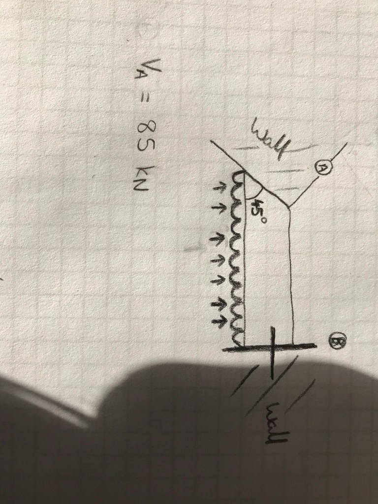
I think as the there is no bond between the two walls that friction alone cannot restrain the 86 kN. I think I should calculate the amount of load that can be taken by the friction (F= u N) away from that end reaction and then treat the B reaction as a reduced cantilever ie increase the shear load in the threaded bar.
Happy for anyone to tell me I’m wrong.
Return of EFC
For those who have read Tom’s blog about EFC this is just a small addition as you can’t add photos to comments it needs its own post. For those who haven’t read Tom’s either go back and read it or ignore this one as I won’t waste time regurgitating what he articulated better than I could and it won’t make sense unless you have.
Basically BAM sent out a message to us temporary works designers encouraging us to use EFC in our designs. It seems that due to lack of codes or experience with it they are not confident on recommending it to larger permanent jobs but they think the temporary works environment is a perfect start for its incorporation. We have been sent both Wagners (Toms post) and CemFree brochures to read. They both offer similar properties and savings.
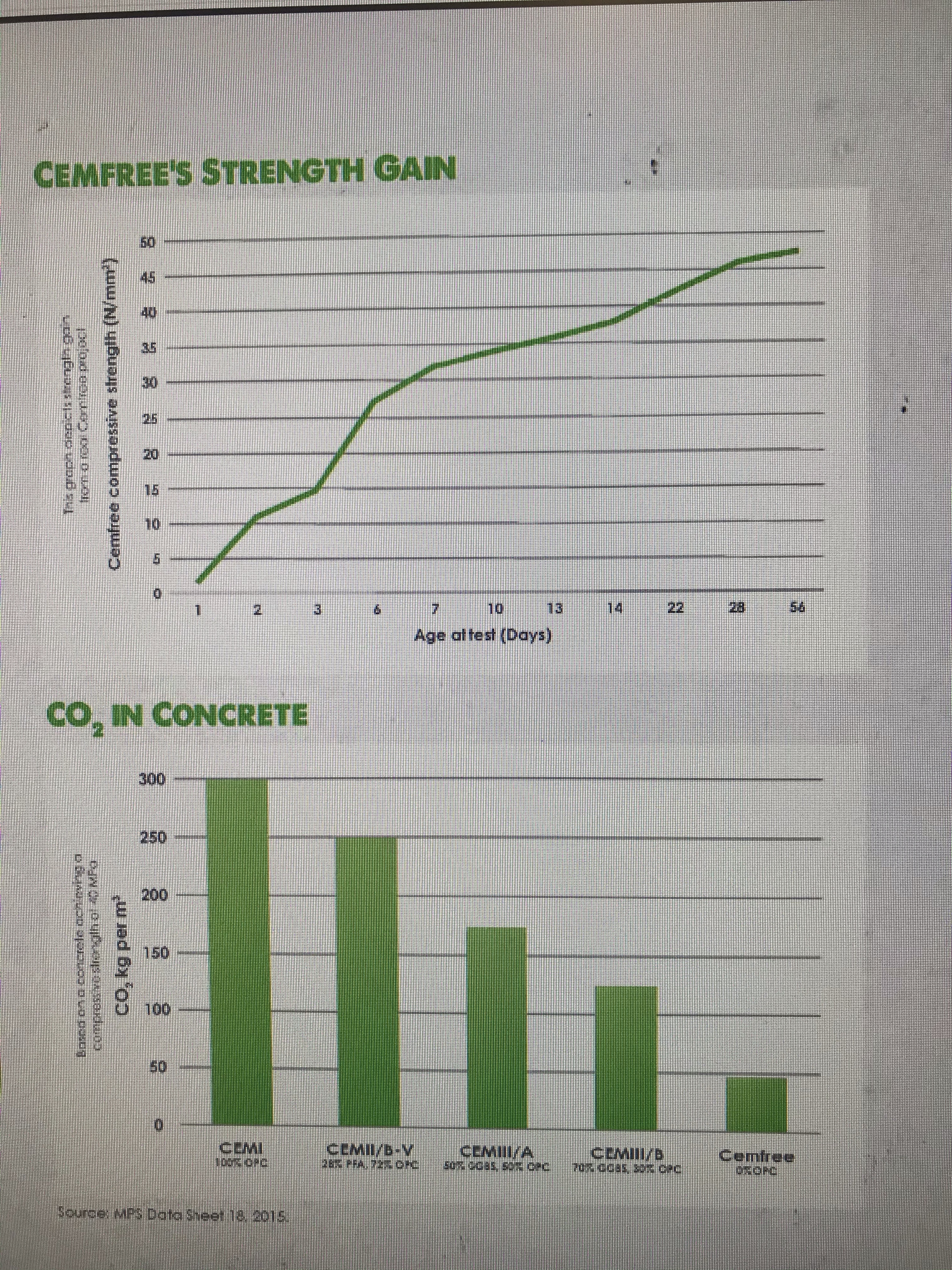
That is the strength and savings promised by CemFree for their product.
The fact BAM have suggested it for temp works first is either due to the lack of risk on our designs (perhaps due to the perceived inefficient low risk designs produced by temporary works designers) or maybe they have worries about its durability.
CemFree advertise a coastal defence job used in Harwich using 100% EFC saving a staggering 88% in embodied carbon, they clearly have no such worries on durability.
I do wonder if the H&S of using AACM instead of cement powder is advantageous as well as there is no mention of the dangers of its powder form on either companies brochure.
Limit State vs Permissible in temporary works
I’ve just designed a temporary timber hoarding using limit state and BS EN 1995 expecting a lolly pop at the end because I “did it thoroughly and correctly” only for the checker to be annoyed they now have to learn 1995 and they can’t use the TWf guides and our internal “cheat sheets”.
I naively thought the choice between design methods was between the stuck in the past engineer vs the modern engineer but I was very wrong. It seems that a lot of the stuff in temporary works is designed using permissible but not all of it.
Anyone have experience with having to chose between the two for temporary works?
I could have designed the hoarding in half the time and probably would have got the same design (maybe my ply would have been 2mm thicker). It’s a balance between design risk and efficiency which temporary works walks a fine line across.
Failure is sometimes an option
As a cohort we have just moved onto Phase 3. I am in my second week at a temporary works design office for BAM Nuttall. To get myself acquainted with the team and some design work, I have been given checking duty for a number of designs. The one I am posting about is a temporary working platform for a sheet piling operation.
The design is for a platform for a piling rig and crane to both travel and work on. The platform has been split into two requirements a haul road and working platform. The contractor specified they wanted to use bogmats (100mm timber planks) instead of aggregate due to the logistics on site. The working platform was designed with 1 layer of bogmats for the whole and 2 layers under the crane outrigger positions.
The checks are conducted simply by calculating the load and subsequent pressure (depending on contact area) on the tarmac and sub-grade and comparing it with their bearing capacity. If the material fails, a layer of bogmats are placed on top and then a recalculation is done with a layer of bogmats to aid distribution of force and hence lower pressure. In the case of the crane outriggers a second layer was needed as the pressures were still beyond the capacity of the soil. There are load cases and partial safety factors but as it is not important to the blog I will not detail them.
An interesting case was determining whether the tarmac haul road needed bogmats or not. The piling rig passed easily because the travelling load is much lower than that of the working load and the large tracks distribute the load onto the tarmac adequately. The crane, however, with its wheels had a much larger pressure.
This amounted to a 921 kPa pressure on the ground. To put this in context the piling rig exerted a 70 kPa pressure.
The ultimate bearing capacity of the tarmac was calculated at 411kPa and therefore failed. This was not all as bad as it seems however. The design continues to assume a 50mm deformation of the 150mm tarmac layer. This sinking of the tyre actually provides a larger contact area between the tyre and the ground. This not only gives a smaller pressure due to the same load being distributed over a larger area, but changes the shape factor in the bearing capacity equation giving a better capacity. After re-modelling the bearing pressure reduced to 290kPa and the bearing capacity of the tarmac increased to 870kPa meaning the crane passed.
This seemed like it was riddled with assumptions to me. Firstly, how do we know the tarmac is deforming 50mm? It was not calculated, it was purely an assumption made. Secondly, how do we know this deformation is purely elastic and wont leave the road rutted after use? I took my queries to the senior designer and he stated that considering the crane is a tracked vehicle it will arrive to site on a tarmac road and it can be assumed the tarmac on site is not dramatically different to that on a road and if the tarmac on the road can take it, the risk is low. Also given the crane is just travelling the risks of any serious incidents should the soil fail are also very low. I didn’t like how the capacity of the ground had doubled from 411 kPa to 870 kPa purely by the load being “embedded” into it. These came from a spreadsheet held within BAM which basically just computes the coarse soil bearing capacity equation :
![]()
This to me is “grey-box thinking” where the engineer who initially designed this, did not necessarily know what he was computing, just the inputs required. Ultimately, I might not feel fully comfortable with the results of the spreadsheet, but I am comfortable with the senior designers assurance that the risk of this particular activity, compared to the rest of the working platform is low. A potential risk to be highlighted in the designers risk register and nothing more.
I guess there are ways of meticulously modelling and calculating all of this but the balance of risk and temporary nature of the platform meant these assumptions and risks were tolerable enough to not bother. It is an interesting study on balancing the design risk with the time (and therefore cost to BAM) to reduce it.
Pile Cap Anchorage
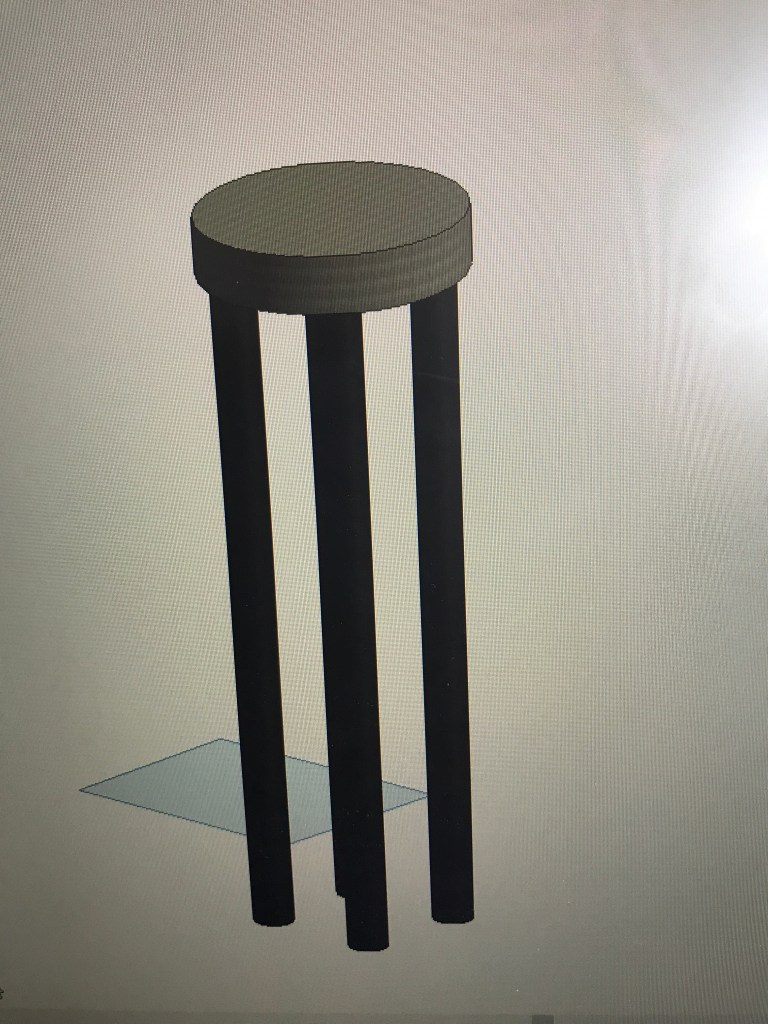
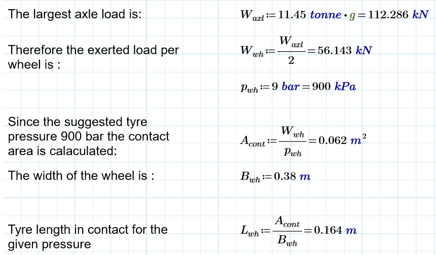
We are currently constructing some pile caps on site. 3,4 and 5 group caps varying between about 1.2 and 2m squared and between 500mm and 1500mm deep. The piles are in place and are being broken out to leave 800mm anchorage standing proud.
The problem is that because of time pressures the caps are now prefab and dropped in as this is a faster process. The challenge is, how do you bend the Anchorage once an entire cage has been places on top?
Does the Anchorage NEED to be bent? The 800mm Anchorage does actually stick out above the smaller pile caps as seen below.
Has anyone encountered this and seen a solution?
All hands to the pump
For those that don’t know I am working on a demolition and rebuild project in Woking. One of the main challenges during my phase 2 has been the live shopping centre and services running around and through the site. As John would say RISK!
Well yesterday that risk was realised when the demolition subbie struck a live water main. I was on site minding my own business when I got a shout and went over to see a 6″ pipe distributing water at some pressure. The pipe had been exposed the day before so it could be isolated in the next few days.

The location of this strike could not have been worse. It is on slight high ground with 3 key low areas around it.
To the left is the demolition site where machines are digging out existing foundations, back filling and constructing a pile mat onto. For those just going through this on phase 1 I’m sure you can reel off the problems flooding a site conducting those activities pose.
To the right ground beams and concrete substructure walls are being cured ready to be back filled and loaded with the GF slab. Again water is not helpful.
Behind is the live shopping centre. As we have demolished part of the shopping centre, the only thing separating the elements and the public is a temporary protection tunnel and crash deck. It has been weathered but would not stand up to a flood, this flooding would mean closing the shopping centre.
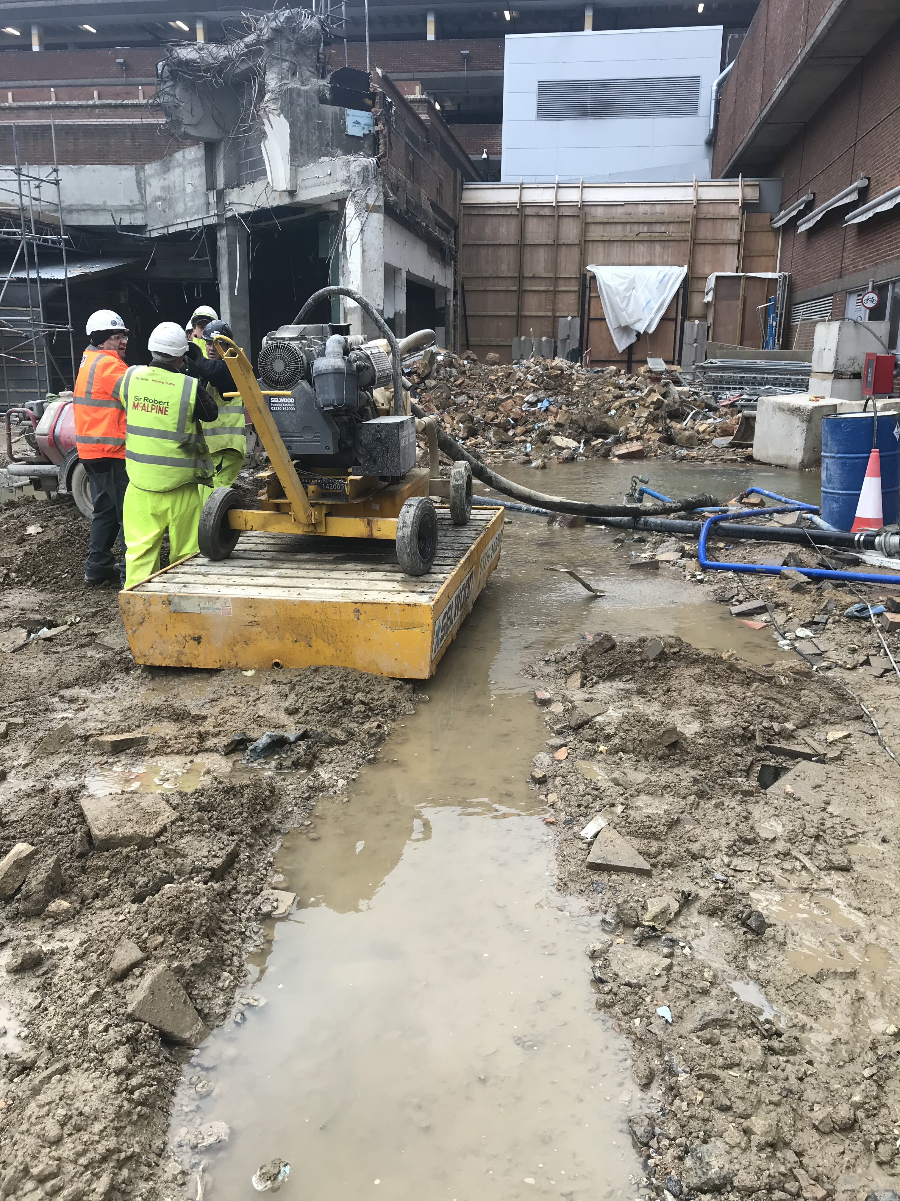
What happened next. Well I instantly went into PITCHPOLE mode and started using demo arisings to create a barrier between the water and the shopping centre. We then had to make a pretty hasty decision what to do with the water so dug a trench to encourage the water along the side of the piling mat.
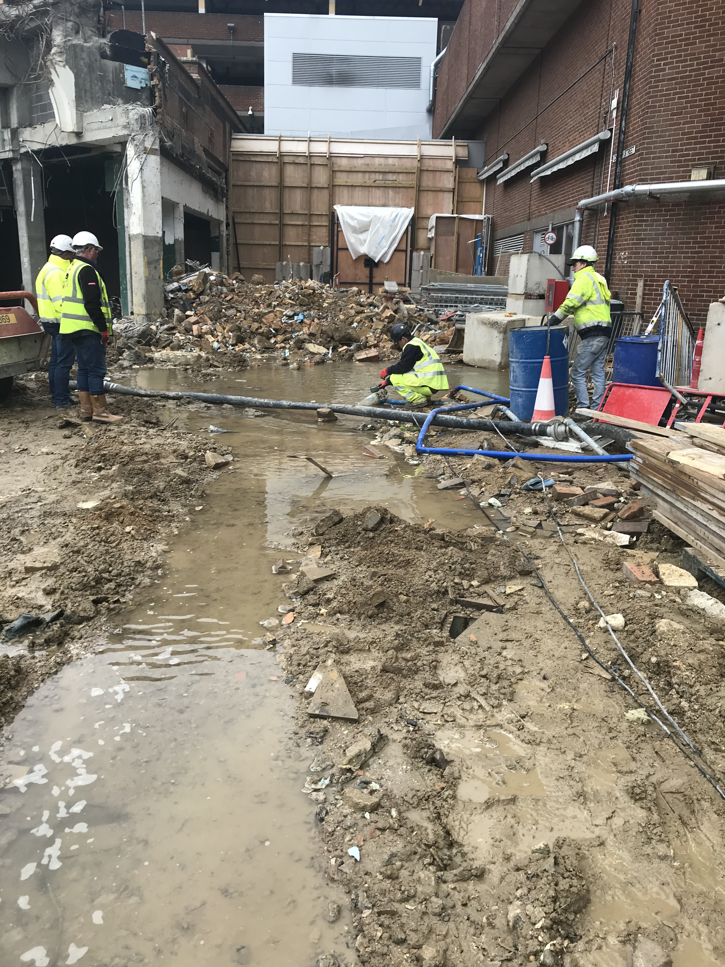
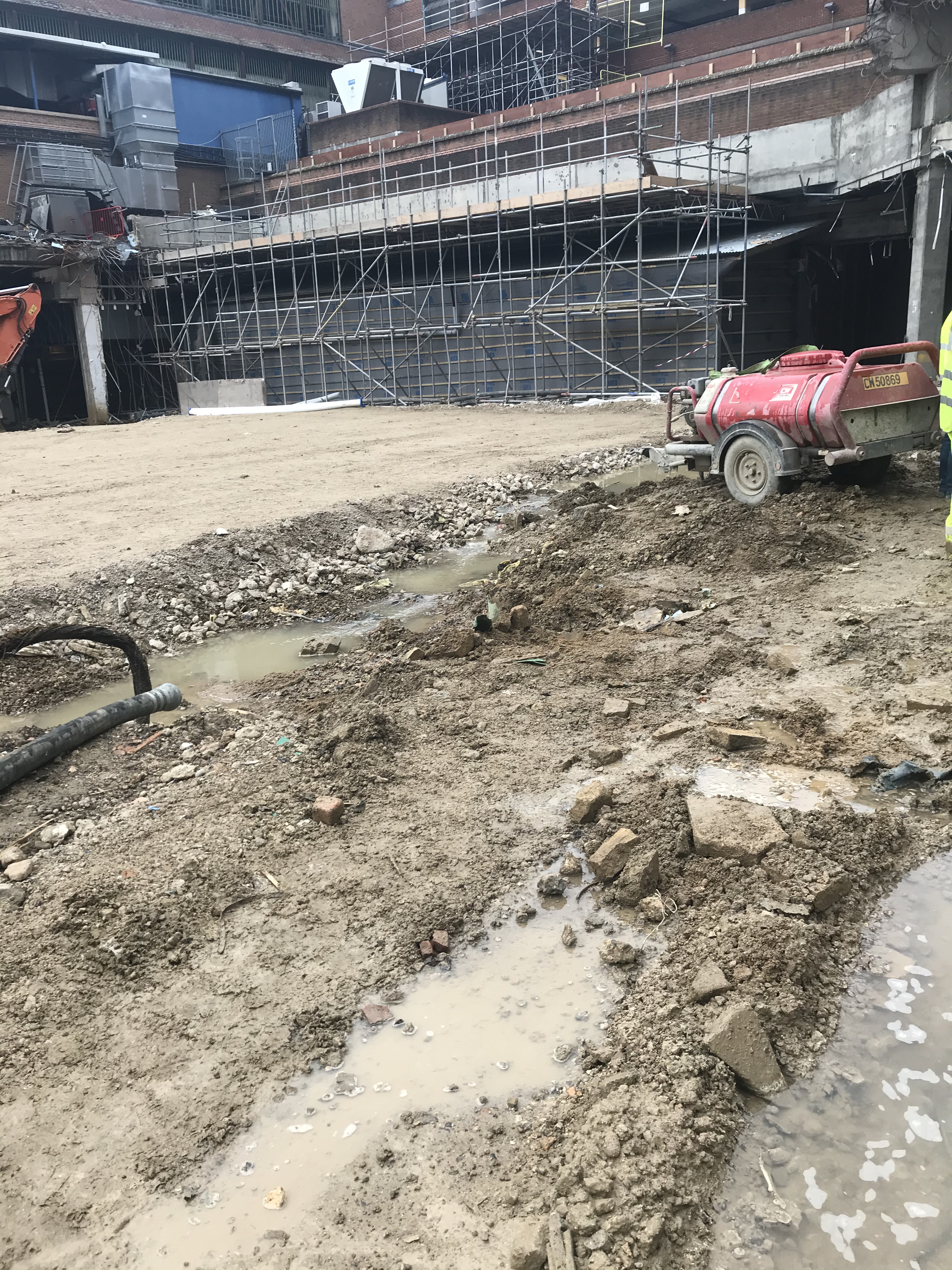
I phoned the M&E engineer for the area and he managed to stem the flow by isolating a valve but couldn’t turn off the entire flow due to it being on a ring main serving greater Woking, they cannot do without water. We made some phone calls and got a large pump on site within 10mins to match the flow of the leak and have stemmed the flooding. Affinity water are not coming onto site until the end of the week so this pump must be run 24/7 until they isolate the ring. 
I’ve been reflecting on our actions and the impacts and if we could have done anything better. As it is we chose to protect the live shopping centre and the concrete curing. We have potentially jeopardised the piling mat by diverting the water towards it, a plate bearing test happening on site today may shine some light to whether this has actually caused damage.
I constantly was suggesting leading a trench into a live foul drain and letting gravity help but there is little appetite to do that considering the disruption it would cause to current works. Also there is the consideration of overwhelming the foul system.
How to demolish around a live substation
Demolition on my job at Victoria Square, Woking is now almost complete. The demolition sub-contractor are in the process of removing the existing strip foundations, backfilling and creating a piling mat with the site won crushed concrete from the demolished structure.
We have a few risks regarding the interface with adjoinging structures such as the live shopping centre and adjacent construction but none are more sensitive than the live substation on footprint of our demoliton.
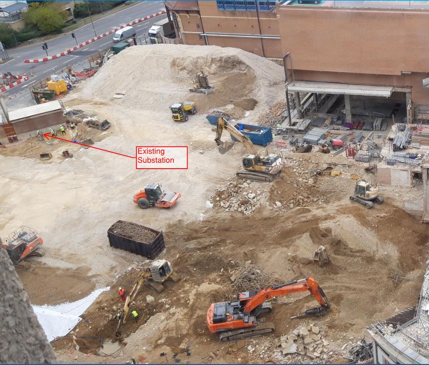
The substation was part of the ToyRUs on the first two levels of the previous structure but feeds a large propotion of the shopping centre and therefore must remain live. UKPN who own the substation have dictated that no vibration above a PPV (Peak Particle Velocity) can be achieved above 5 mm/s and there is a vibration monitor fixed to the substation to ensure this.
The problem is the substation sits on the foundation we need to remove and we are creating a signifficant amount of piles and substructure very close to the extent of the walls.
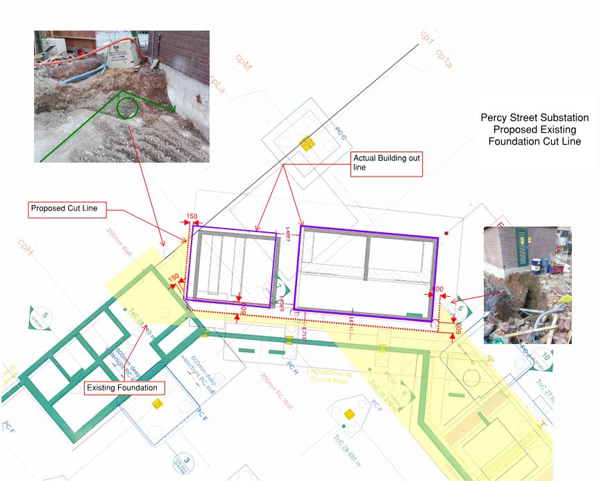
The yellow designates the foundation to be removed and you should also just be able to see the ground beams, pile caps and piles being installed in the coming months. There was the added complication that the exact location of the substation was slightly off during the design of the new structure (compare the grey lines on the drawing to our overlaid purple lines) which make these tollerances even tighter.
The vibration of installing piles so close to the substation is being mitigated by use of a CFA method (although this was always going to be the chosen method anyway as it was selected for the rest of the site) but it still leaves the problem of breaking out a 1.5m deep reinforced concrete foundation 150mm from the substation which isnt allowed to experience vibration. The solution…


Diamond stitch drilling. By using a 150mm diamond drill bit and drilling along a given line around the substation overlapping the holes creates a seperation of 150mm of the foundation under the substation and the foundation to be removed. This is an incredibly slow process with each driller completing less than a metre a day each. With 4 operators on site this will still be nearly 2 weeks work.
In the photo you can see 4 drill rigs set up as the drill out cores of the foundation. It hasnt been raining that soggy foundation is caused by the amount of water used to keep the drill piece cool.
I still have my reservation on whether this will prevent vibration when it comes to removing this foundation considering I feel it in the site office, but it shows we are taking practicable measures to comply with UKPN targets. Whether UKPN have set unreasonable targets is a question for another time I guess, a quick bit of research told me that structures can normally resist up to 20mm/s but I dont have a full understanding of sensitivites to generators or transformers that may be inside.
Plate bearing test
Victoria Square Woking are currently in the process of removing the existing shallow foundations of an old car park so they can construct CFA piled foundations for the new car park.
The demolition contractor are obligated to leave site with 1) the guarantee there is no existing structure in the ground and 2) the ground is of sufficient strength to support the piling (create a piling mat)
Yesterday on site the demolition subcontractor brought a plate bearing test team onto site to ensure the sub grade was of a high enough capacity before continuing up. An intermediary test. I thought I would share the test in case any of you were interested.
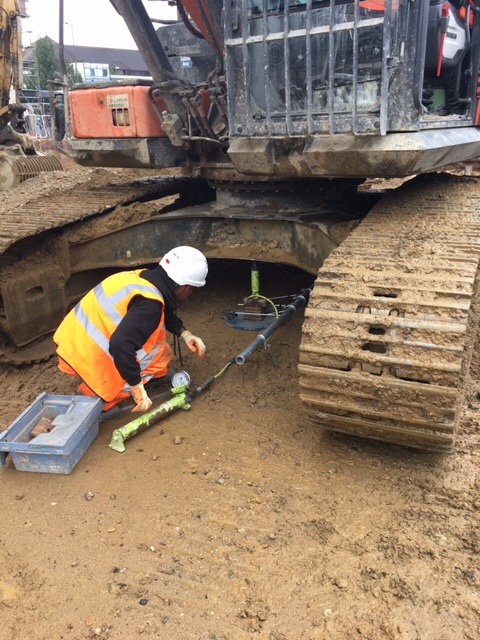

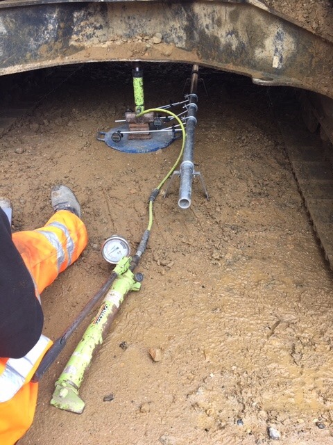
Effectively what is happening is a plate is placed under one of the excavator machines and a hydraulic jack is connected to the two. When the jack is lifted a gauge informs the operator what pressure the plate is under.
A scaffold tube is placed next to the plate with three strain gauges fixed to the plate. The differential movement between the scaffold tube and the plate offer an immediate settlement value for the plate. Once you’ve got both pressure and immediate settlement calculations can be performed to give a CBR %.
I am still awaiting the report back but the guy on site said we achieved 25% which is good considering our specification was to hit 5%
The good ideas club
The Woking parking complex has now been demolished to ground level and the strip out of the ground floor slab and foundations has begun.
The current foundations are large shallow strip foundations at approximately 7m in width, 1.5m depth and 70m in length. They are heavily reinforced and approximately 1.5m below the ground force slab.
The structural designer has planned for the entire removal of the foundations to make way for the piles and pile caps that will be replacing them. However, ever the opportunist our demolition subcontract has had the idea to only remove the sections of the strips that would collide with the new pile caps to save time, money and waste. His argument also that the hole in the foundation would save time on having to build and strike formwork.
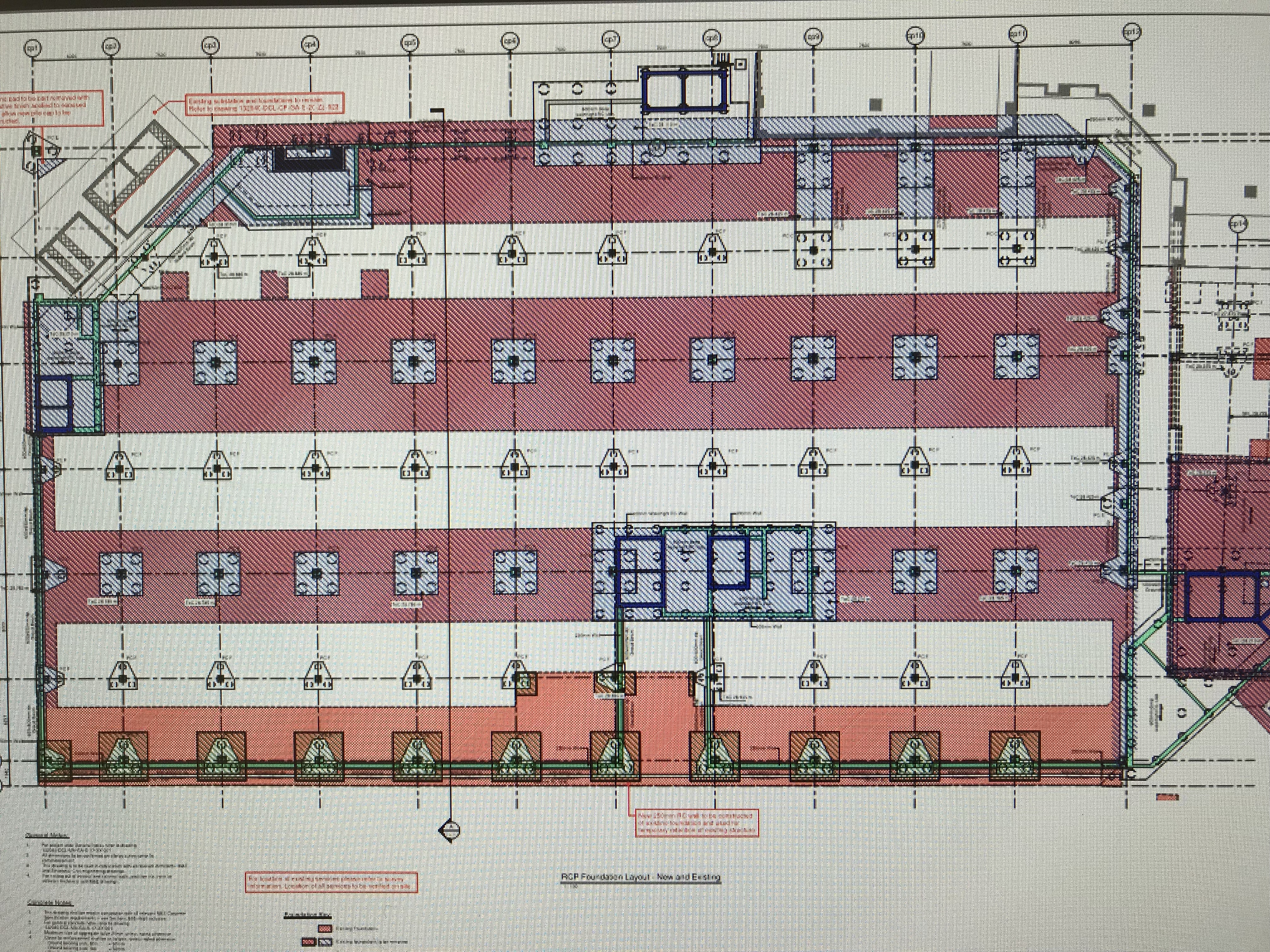
The drawing above shows in pink the existing foundations with the proposed. It sounds perfect on paper, but the question remained would it really be easier to precision cut out sections of a foundation at depth rather than dig the entire lot up.
The first challenge was the depth. The batter needed to get down to that depth is around 1.5m. The centre point of the proposed pile caps are 7m c/c and the caps themselves are 3m wide. If you excavate this cap with the batter that does not actually save you much in terms of excavated fill. It also means your site is 2/3 hole and 1/3 trackable access.
Secondly was the rebar. Bulk removal with a leading edge would simply mean using a muncher to rip up the rebar. However the process of leaving holes in the foundations requires a breaker machine followed by a bloke hot cutting the rebar instead. A trial foundation was dug on site this week and the whole process took 2 days for one pile cap. 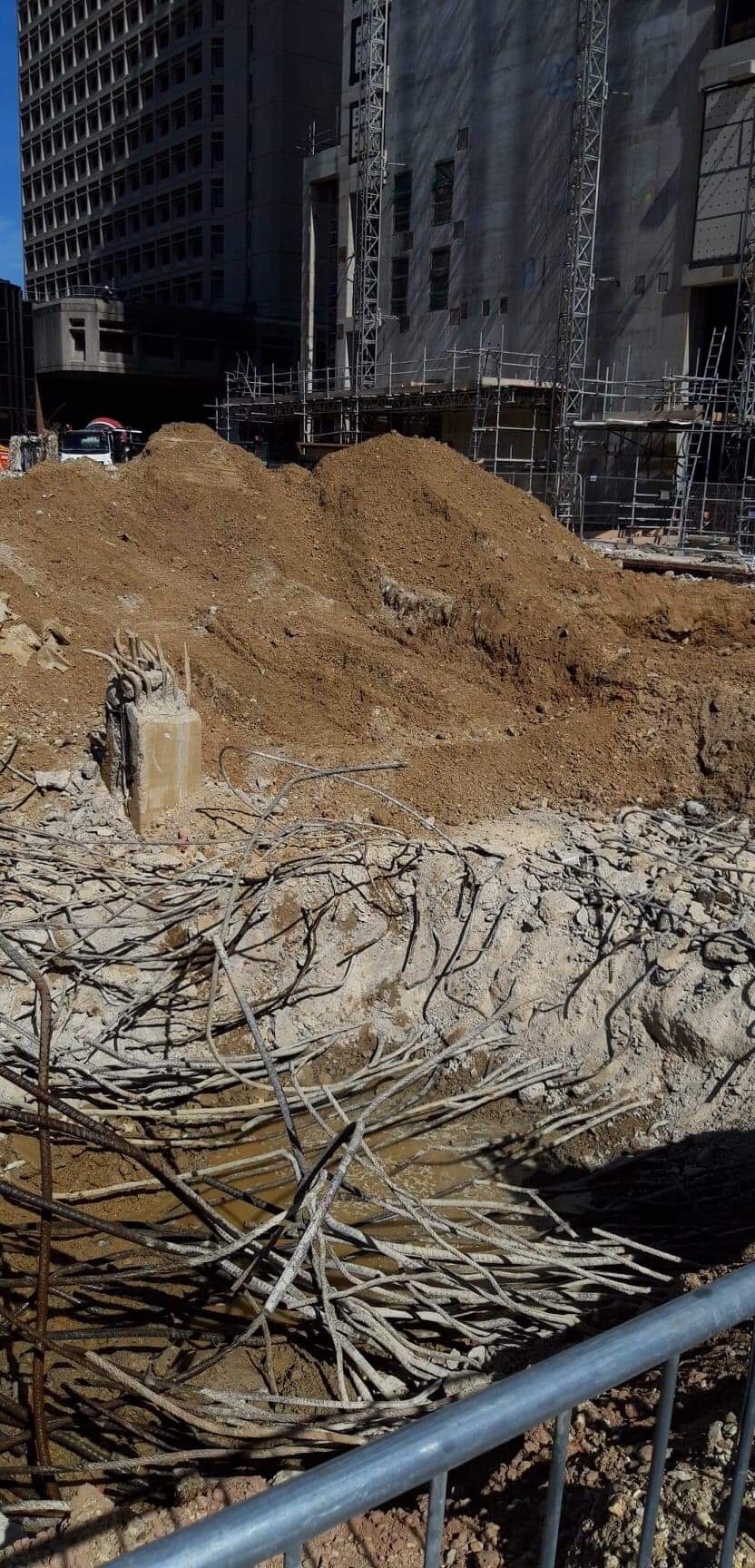
the photo above is the trial attempt to “neatly form a hole in the existing foundation”.
In my eyes value engineering has its place and innovation should be considered, but there is a time and a place and I don’t think it worked this time. As the PC we were all sceptical but allowed the SC to trial it, they can chose whether they persist with this methodology but they will not receive an instruction from us to permit them any further allowances.
