Archive
Tearing it up
Having spent over 3 months watching 5no 13tonne excavators peck and break at my structure level by level (my first blog) a change in tactic has excited me enough to share.
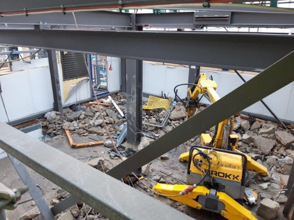
Effectively due to the phone masts fixed to the central core not being decommissioned in time the central core remained upright while the rest of the building was demolished down to ground floor. This left the quandary of how to demolish the remaining core after the masts were finally decommissioned 3 months late.
The same tactic could not be employed as there was no ramp in the core which the plant could drive down so a crane would need to have lifted them from floor to floor. Also an entire scaffold wrap would have needed to be constructed around the core to offer edge protection, dust suppression and access to the workers. All of this was not impossible but potentially long winded.
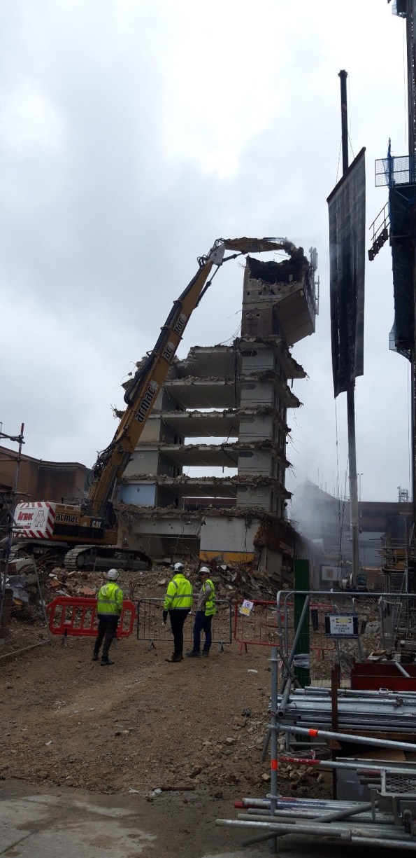
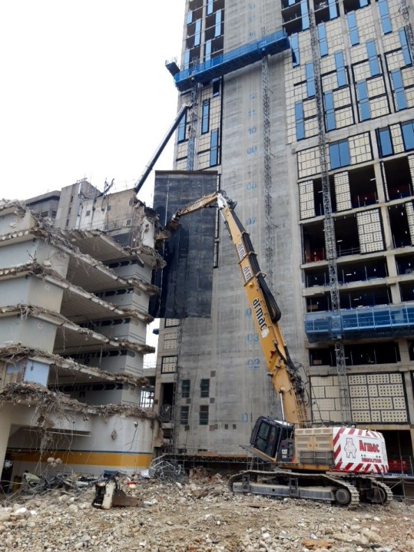
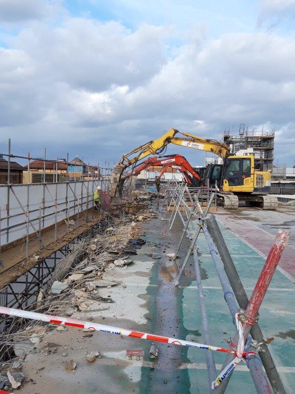
Instead the decision was made to pay for a 110tonne monster to come to site with an “extra long reach excavation arm” and demolish everything from the ground. This raised issues such as trying to suppress dust from the ground would have been impossible and flying debris at 40m flying around site. The solution- the long reach arm has a host attachment that sprays water from the breaker onto the slab as it goes. A large crane will hold up a rubber Matt to prevent debris hitting adjacent construction with an exclusion zone at ground level.
The site of this bad boy on site has produced a bit of a viewing gallery and some buzz on site so I thought I would post pictures. Any questions on the decision making or added risks feel free to ask.
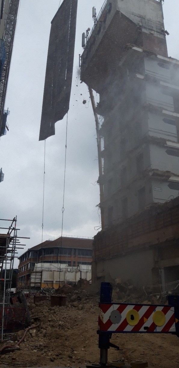
2 concrete sacks preventing the rubber matting twisting or glittering into adjacent construction

Rebar Near Miss
I thought I would share a near miss that could have ended very badly on my site last week. It is still currently under investigation so this information is as accurate as I have it at the moment but is still a little sensitive.
The demolition of the car park is about 70% complete and we are working approximately only 10-15 metres above street level. At the time of the incident we were on floor 2 demolishing a beam and column on the leading edge of a cantilevered section.
The procedure had been always to break the cantilever from the top completely, clear the rubble and then move the plant backwards a structural bay and start on the main slab. As the slab is much thinner than the beam of the cantilever the machines normally leave the beams until last. A 13t excavator will break the concrete off the beam and then use its arm to bend the rebar downwards so it is not protruding. A worker with a gas cutter will then follow behind and trim this bar.
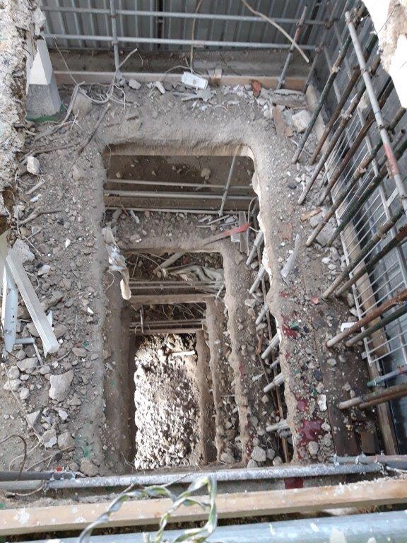
On this particular day the job was assigned to a new driver who in turn was using an 8t breaker which did not have the power to bend the rebar with its arm. The driver after breaking out the concrete could not bend the bar and instead of waiting for the bar to be bent by someone else just continued the job. He began breaking the top of the concrete column the beam was fixed to. This lead to the loosening of the protruding rebar and eventually it became dislodged and fell from its position, through the scaffolding onto the street below.  This photo shows where the rebar fell from the staircase and the pod it hit below
This was 5m of 32mm bar weighing approximately 30kg. It landed on a bathroom pod that was being delivered at the time and skewered it straight through writing the pod off. It goes without saying that had the delivery not been taking place it is just as likely a person could have been stood in the exact position. 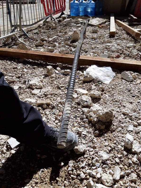 This is the offending bit of rebar. My foot for scale (size 9)
Conclusion: The machine operative was sacked that day. The method statement has subsequently been re-written now that when attacking columns with cantilever rebar still attached it must be attacked from the bottom and once the concrete is removed the whole column may be bent down by a 13t only. This previously was not done because of the risk of the larger structure falling onto the floor and causing collapse of the slab with the machine still on top. To prevent this the machine must reverse a structural bay back before pulling the beam down. 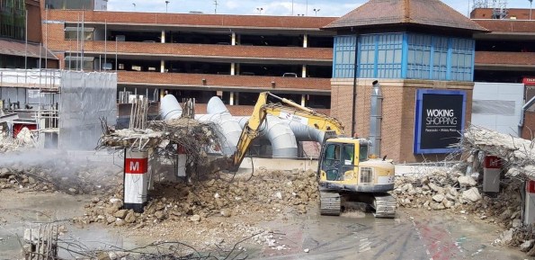 This photo is the new method of leaving some concrete above to keep the rebar secured and then break the bottom of the column.
I have tried my best to explain the procedure but I have attached photos that hopefully paint the picture.
I must say relationships before the incident were of mutual trust and SRM were happy to let the subbie a little slack, since the incident SRM have tightened the lead a little and it is leading to tension on site. The subbie maintain it was a “freak accident” but then why would they sack the operator? SRM monitor and grade their SC on a monthly basis and that goes into a central company tender database – something tells me this subbie may not be selected again.
Top cover
I was walking to my demolition site last week and noticed a peculiar pattern on a concrete slab which had been poured as part of the new retail area.
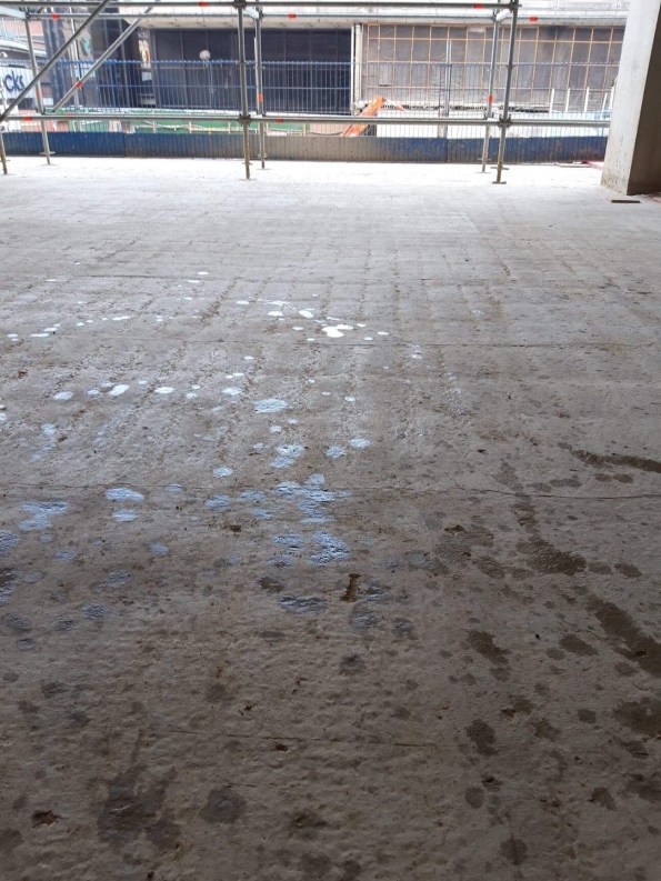
It seemed unintentional so I asked a surveyor who was there when it was poured (as it was before my time) and he told me what happened. I thought it was interesting so I thought I would share it.
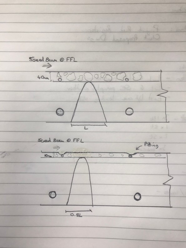
The slab is constructed with top and bottom reinforcement. The mesh at the top of the slab is held in suspension by small “chairs”. The problem arose from the chairs being the wrong size and therefore pushing the top mesh higher than it should have been. As the FFL was set the mesh ate into the top cover which was only 10mm where it should have been 40mm.
When the screed beam finished the aggregate in the concrete was pushed off the mesh as it was too big to sit between the FFL and the mesh. This meant that in the exact local of the mesh, there is no aggregate and a weaker cement mixture left. This has led to local settling of the slab in the exact footprint of the mesh.
It seems that this could have been rectified by a pre pour check and if it was identified the mesh was too high then the legs could have been spread out to lower the top, the legs clipped or smaller chairs ordered.
For whatever reason this didn’t happen. The fact this has been left might mean that the floor finish might cover these sins but it will not help with the durability of this slab.
Is this ground a risk?
I am currently sitting in a small team overlooking the demolition and then reconstruction of a car park in Woking.
The project manager has tasked me with setting the piling Matt levels to allow the piling contractor a flat even surface. We have decided on two piling Matt levels (ramp and car park) across the site with a battered edge between them to allow for the different ground slabs. The street level is approximately 28.5 to give an idea of how this will look on the ground.
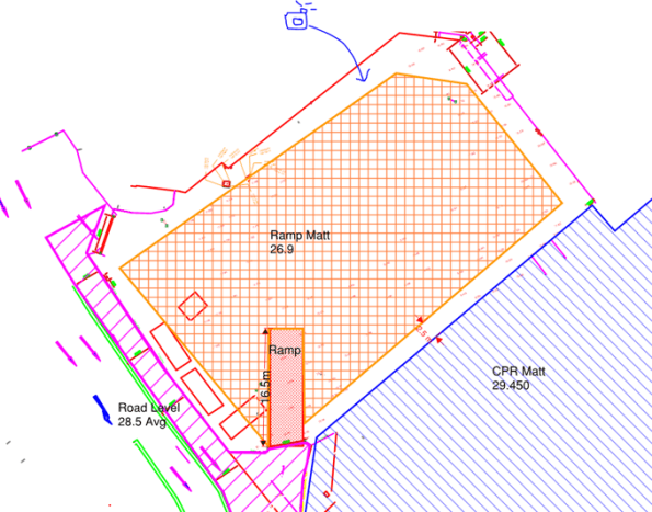
The ramp into the CPR cannot be seen on this drawing but does exist.
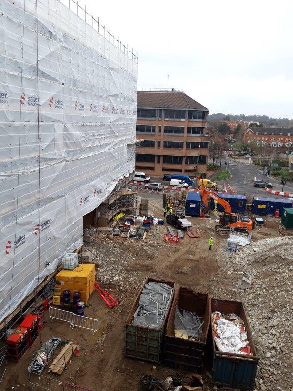
My main concern is with the level of the “Ramp Matt” which is adjacent to a Primark and Debenhams to the north and east. Looking at this problem it seems that we would be undermining the foundations of the existing buildings to excavate down to 26.9. Nobody seems to be able to tell me what foundations sit underneath Debenhams or provide any GI data beyond “it’s a clayey sand”. So it seems like an obvious answer, you need a retaining structure between Debenhams and the proposed piling Matt, but the plot thickens…
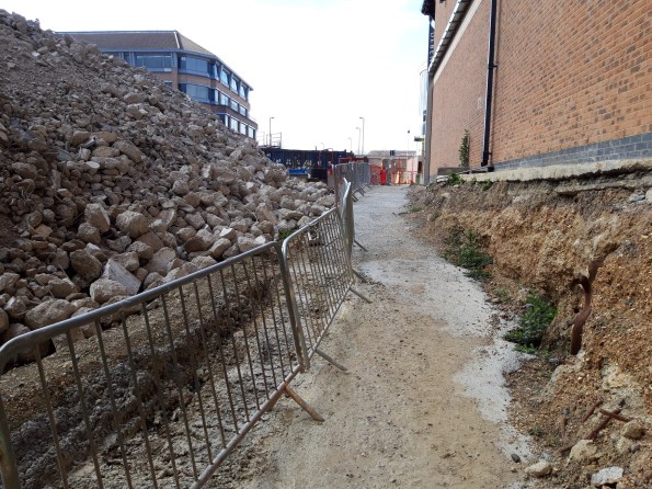
The ground has already been part excavated to allow access for workers and is standing freely. There is no evidence of the foundations under Debenhams and the ground seems to be holding. Supposedly this has been the case for the last 18 months. I asked who led with the initial excavation and it seems it was “just done”.
That photo is taken at the proposed level of the piling Matt but the ground rises into the far ground up to street level, the proposed Matt will remove that rise so the whole ground sits at the level the photo is taken at. It seems to me that the attitude is simply “it’s ok now so it’ll be ok to take the rest out” without anyone raising any alarm bells. Am I crazy or is this in need of an actual substantial design?
Red Car Park Demolition
I have just started phase 2 on a demolition job for a car park on the Victoria square redevelopment in Woking. I realise that we don’t really cover demolition in phase 1 so thought I would share some photos and information on how they are doing it as a general interest piece.
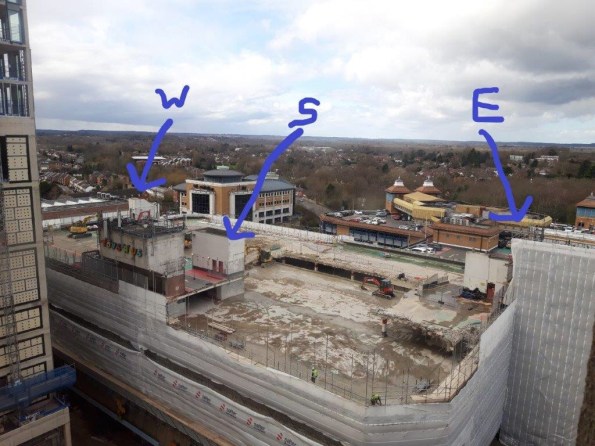
The car park has 3 cores, the South and East have a lift and staircase while the West just a staircase. The methodology is simple, the excavators work in pairs (one pecking and one munching) to remove the slab. They always work on floor up to prevent the support underneath being undermined. There was a structural load test conducted of the slab and it was determined that 1 x 13t piece of plant can stay in one structural bay with 1.5t of rubble around it to prevent collapse.
The lift cores have a concrete slab roof which is removed by a remote control pecker for H&S reasons.
When the workers start a new floor the priority is the parapet wall and then the 2m cantilever at the edge of each floor. There is a demarcation to ensure no plant is to cross onto the cantilever
All rubble is collected by small BOBCAT shovel shifters and dropped down a shoot to the ground floor. This shoot is closely protected to prevent any labourer wondering close by.
The plant works in a methodical order, much like painting a floor in your house to ensure they don’t leave themselves trapped on a level. The rubble is then removed by a 20t excavator on street level into skips that are removed daily.
There have been issues this week with high winds ripping the protective sheeting off the scaffold which means demolition can’t take place and today the temporary water pipe used for dust suppression was broken when rubble fell down the lift shaft from the slab above and broke it in two.
Plenty of engineering challenges to come as the client seeks to keep the adjoining shopping centre open while demolishing the concrete frame around it.
Any interested questions regarding demolition send my way.
