Archive
With Great Power(Point) Comes Great Responsibility!
A quick blog about conflicting relationships on my design project.
(Credit to Glynn Tomsett for the title)

I am currently working on a project which involves developing a base concept design for upgrading the Melbourne Airport short stay car park, serving Terminals 1-3, in line with a wider airport expansion programme.
The design includes re-configuration of the current floor plans to include pick-up and drop-off, additional entry and exit ramps to cater for increased traffic flow and development of pedestrian access to the terminals.
The client, Melbourne Airport, engaged my design consultant along with an architectural firm to take on the work late last year. They subsequently contracted a PM firm to manage the project.
I attended an interim client meeting a week or two ago, which involved the design consultant (us) and architects presenting their ‘optioneering’ to the PM team ahead of delivery to Melbourne Airport’s Board of Directors. During the presentation it became apparent that we were pulling in slightly different directions from the architect, who was eager to push the ‘all singing all dancing option’ with a new orientation space (structure) in front of the car park and 2 new fandangled pedestrian bridges. It might have been that there were 20+ bodies crammed into a single glazed room with broken air-conditioning on a sweltering Melbourne day, but I could definitely sense a bit of tension in the air, so I did a bit of digging.
It turns out that when we were originally engaged on the project with the architect there was no direction on who was to lead the design effort so both parties went off in their own direction. Predictably, the architects came up with a number of flowing designs that boasted ‘confluences’ and ‘spaciality’ etc, but which required extensive structural work and in some instances were unfeasible.
By all accounts they did not take kindly to the engineering advice from Aurecon about the feasibility of some of their ideas and this caused some early conflict between the parties. It wasn’t until the PM firm were engaged that the matter was resolved after they appointed Aurecon the lead coordinator of the design effort.
From what I have seen however, this hasn’t stopped the architect from attempting to force their ideas on the project and they are obviously keen to retain as much influence/control over the design as possible, including what information gets delivered to the client.
Following the meeting I attended, the PM team identified quite a few areas in the presentation that needed further development and tightening up ahead of delivery to the Melbourne Airport Board of Directors. It was agreed that the architect who had compiled the original presentation would send it through to us work on update. What followed was a frantic 1 1/2 days of pulling together the required information ahead of the meeting.
The team were literally working to get the presentation up to scratch right up to the minute the taxi arrived to pick them up. I didn’t attend this meeting, however, when the design manager got there the architect had already arrived and had a presentation on the screen ready to go. When she explained that she had the updated presentation which the team had worked hard on, the architect refused point blank to swap it over and after some discussion (conscience not to cause a scene in front of the client) she ceded and the presentation was delivered using the original version which had only a few minor amendments made by the architect.
I was quite surprised at this level of childish behavior, an indication I suppose of the architect’s need to maintain some control over the project to justify their position and inject as much architectural scope as possible.
I wondered if anyone else had any other anecdotes about conflicts between parties from their placements?
Screw it!!
Another quick blog about something that came up in conversation yesterday with my Phase 3 mentor, which potentially has application to military construction and disaster relief operations.
BLUF
If not already used, could screw piles have an application for short to medium term RE infrastructure projects and limit groundworks and the need for reinforced concrete foundations?


BACKGROUND
My mentor here is chartered with the ICE and spent 10 or so years working in the UK, before coming out to Australia. One of the pieces of evidence he used in his CPR was his introduction of screw piles to the highways agency for the erection of gantry signs along carriageways.
Apparently screw piles had been in use by the rail industry for some time, but the technology hadn’t made its way into other sectors. He was working on a roads project somewhere along the M6 near Birmingham which included the installation of a number of new overhead gantry signs. Traditionally the foundations for a gantry would have been one of either;
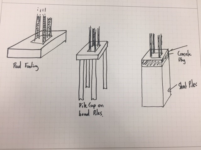
- Concrete pad footing large enough to deal with overturning actions
- Pile cap on top of bored piles
- Sheet pile box with concrete plug in the top.
Some of the considerations for the erection of gantry signs and any other roads infrastructure are;
- Time on site (Reducing the need for traffic control measures and risk to road crew of working next to live traffic)
- Ability to remove/relocate structure to accommodate future development, road widening etc.
He identified that the traditional methods described above weren’t necessarily suited to this as piling works take time and equipment, and concreting needs prep and curing times. Additionally you aren’t left with too many options but to break out the concrete if you need to move or relocate assets, which isn’t very sustainable especially if your leaving 10 or so metre piles in the ground.
SCREW PILES
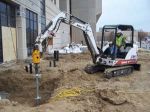
Screw piles on the other hand can be installed very quickly and need minimum plant, the attachment for screwing in the pile can be fitted to an excavator or skid steer for example, so very much scalable;


Once installed a simple grillage can be bolted to the piles to provide a connection for your gantry. Once the gantry is no longer required, the structure can simply be dismantled, the screws piles removed and re-used elsewhere.
MILITARY APPLICATION?
Something as simple as this, strikes me as a low tech, adaptable foundation solution which can be rapidly employed across different environments and avoid the need for lengthy and costly groundworks. From my brief reading, it appears the bearing capacity/hold down force required is achieved by screwing in the pile (in the example I looked at typically 2m sections which bolt together) until a specific torque is reached which determines you have reached the desired capacity. This suggests to me you might be able to avoid the need for lengthy geotechnical investigations (to some extent) and simply extend your screw piles to reach the desired capacity. This might be an over simplification…I think you can summarise the pros and cons as follows;
PROs
- Low tech
- Limited plant requirement which is standard to a plant troop
- Scalable; can easily up size piles or increase the number of piles
- Flexible; if the pile doesn’t achieve the desired capacity add sections and keep going
- Avoids ground works (especially in poor or wet ground)
- Rapid installation
- Re-useable/sustainable
CONs
- Limited capacity compared to traditional piles (This might not be an issue as unlikely to need significant capacity);
Fig below show the ultimate tensile capacity (take as a displacement of 20% of screw dia) for 100mm dia screws with different helix spacing tested at 3.05m (circles) and 6.10m (triangles). Material was 2m stiff silty-clay overlaying a deposit of lacustrine varved clay (Undrained shear strength 200KPa and 30KPa)

Note: spacing of helix’ is important in determining whether the plates act independently or in a cylindrical shear method
- Logistic burden; Probably not going to be available locally so would need to be freighted to op theatre. concrete on the other hand can generally be sourced locally
- Not suited to rock; not sure what strength of material would preclude their use.
while I was looking into these it got me thinking about a JFEE I did in Kenya a few years back which included the construction of a community centre. The previous Sqn had a number of issues with the foundations, which if I remember correctly was mainly down to the weather and rain filling the excavations and shrink/swell issues with the murrum. Could this potentially have been avoided through the use of screw piles? Screw piles seem equally suited to disaster relief operations and is seismic areas the ability to re-use them could provide an advantage over concrete foundations which presumably would become U/S after an earthquake?
THOUGHTS?
I’d be interested to hear what people think about the application of these for the Corps, or have we already used them? Has anyone come across them on one of their projects ?
“A good consultant does what we ask of them, a great consultant challenges our thinking”
I thought I would just share a quick blog after I attended a ‘Design to innovate’ workshop on my Phase 3 attachment with Aurecon today.
Aurecon is big multi-national company formed out of the merger of Africon, Connell Wagner and Ninham Strand in 2009. It’s main markets are Australia/NZ, Asia and parts of Africa. Its big selling point is that it claims to offer a different service from ‘all the other consultants out there’ and it has been described as the Google of the design world.
while I have initially been a bit cynical about this self styled approach, the quote I have titled this blog with came up in my workshop today and I thought it was quite good. The workshop then went on to explain the background to Aurecon’s thinking and introduced the ‘Blue Ocean Strategy’, a concept which was new to me and one I thought worthy of sharing for those who haven’t come across it. Rather than try and explain it myself, the short 2 1/2 minute video below will give you the idea;
Aurecon are trying to provide the next level of service in design consultancy, by improving the client experience and pushing the boundaries of the traditional design service. An example of this is that they are actively identifying future issues in their market areas, designing against them and them approaching clients with a solution to a problem they don’t necessarily yet know they are going to have.
I am not yet 100% convinced how much of what they are offering is new (and given my lack of experience I have nothing to compare against), but am interested to see what I pick up over the next couple of months. Maybe everyone else consultant has a similar pitch..?!
Marginal Gains….
I am now a couple of weeks into my Phase 3 attachment and while digging into some information on a project I am involved in I picked up something which I thought was quite interesting and worth putting out there for comparison against other design consultants.
Reading the Risk Assessment which was completed during the tender stage I came across an entry which highlighted a predicted profit margin of 60% as a risk and a comment which indicate this was an “aggressive” tender in the hope of securing the bid and a foot in the door for future works on this major project.
I was (maybe naively) quite surprised at this. Not having any experience of working in a design consultancy I didn’t really know what to expect, but this seemed a pretty significant margin. I had a chat with my design manager to get a better understanding of the situation and found out that actually 65 -70% is the normal range on projects and 58% is the minimum allowable margin.
I was curious to know how this bears up against other people’s experience, particularly on jobs in the UK and US vs Aus?
A Gantry Crane Bridge Too Far?
I recently had the pleasure of a week of night shift on my project (fortunately it will be my only one), during which I was responsible for overseeing the installation of the first half of a 90T beam on which a gantry crane will run to lift sections of the Tunnel Boring Machine (TBM) from the surface into the portal structure prior to launch.
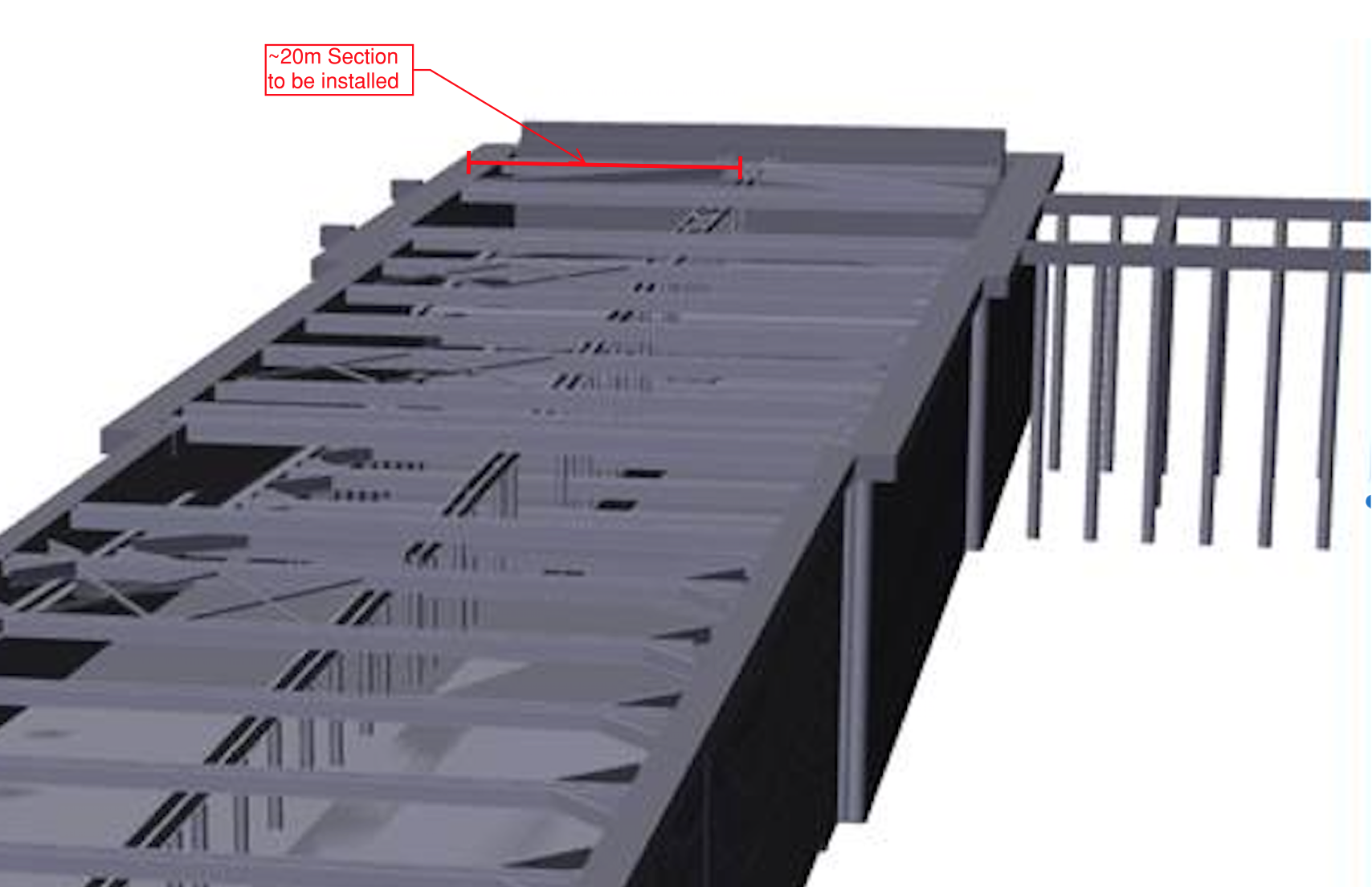
Fig 1. Highlighted gantry crane section
I had the night before been thrown a hospital pass and asked to install the bearing plate for the beam which sits in a recess in the capping beam, but that’s another story and it did eventually go in, see Fig. 2 below.
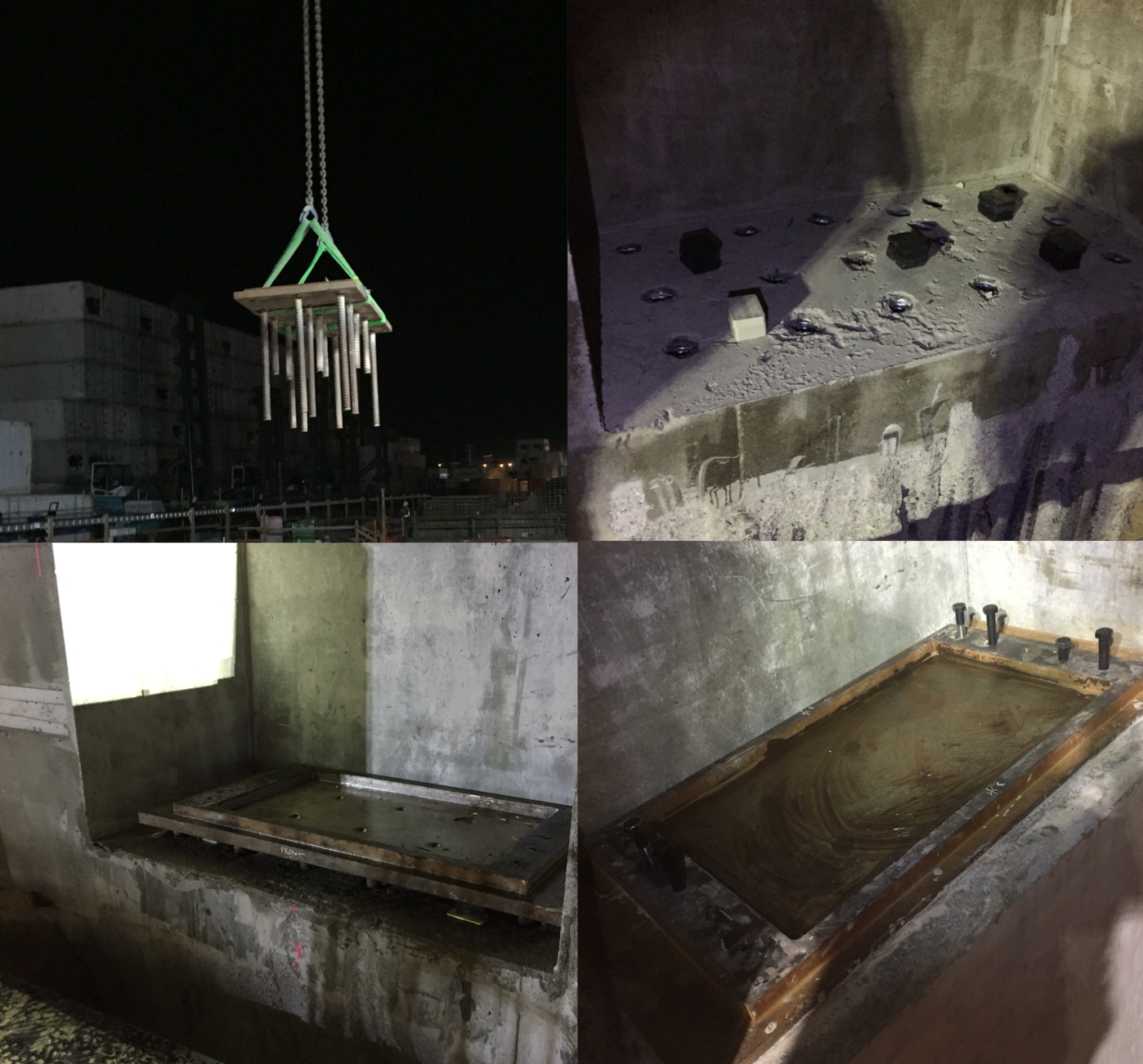
Fig 2. Installation of bearing plate
The installation of the gantry crane beam was quite simple, as you can see from the following photos, and the whole operation went quite smoothly;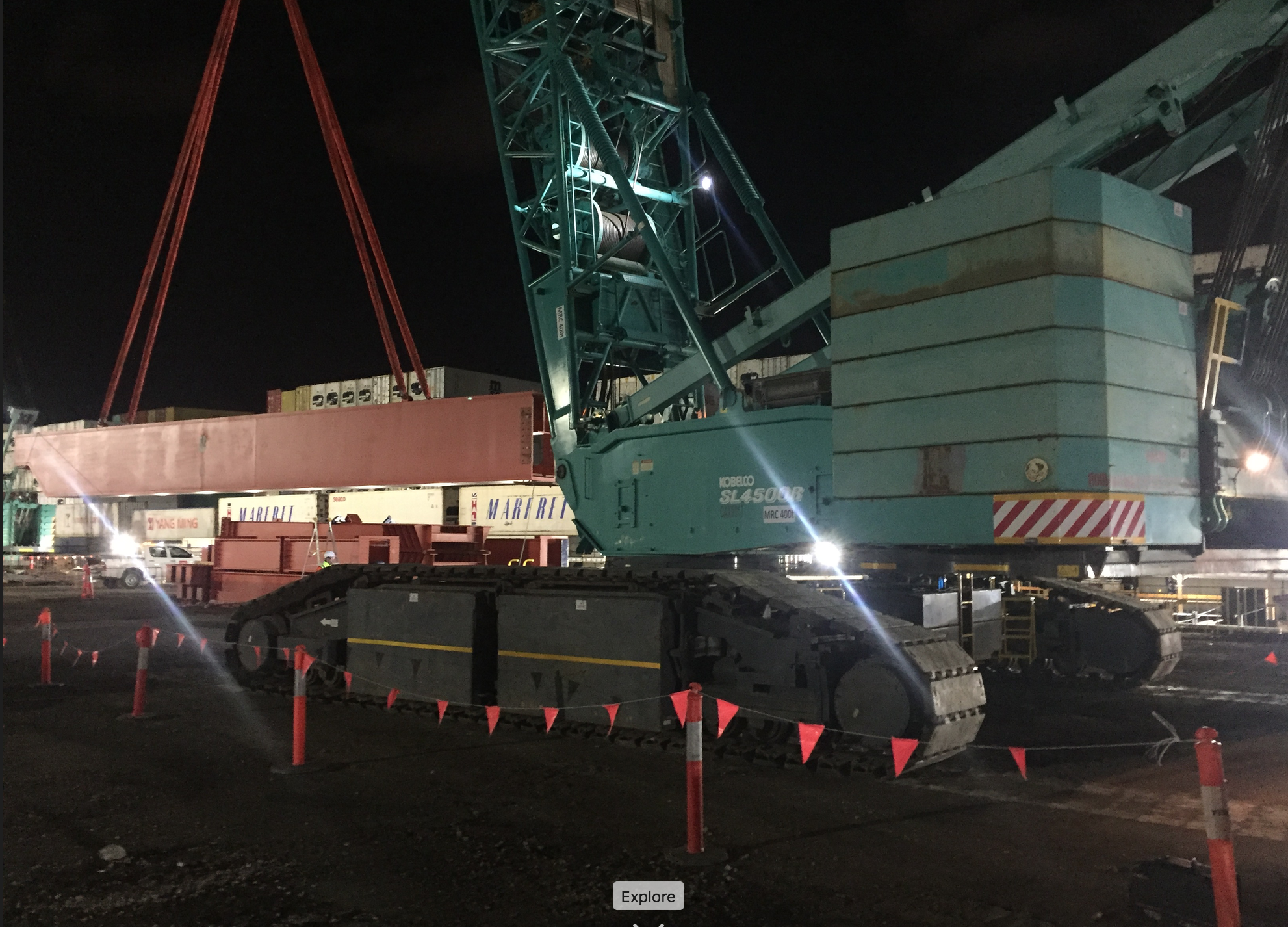
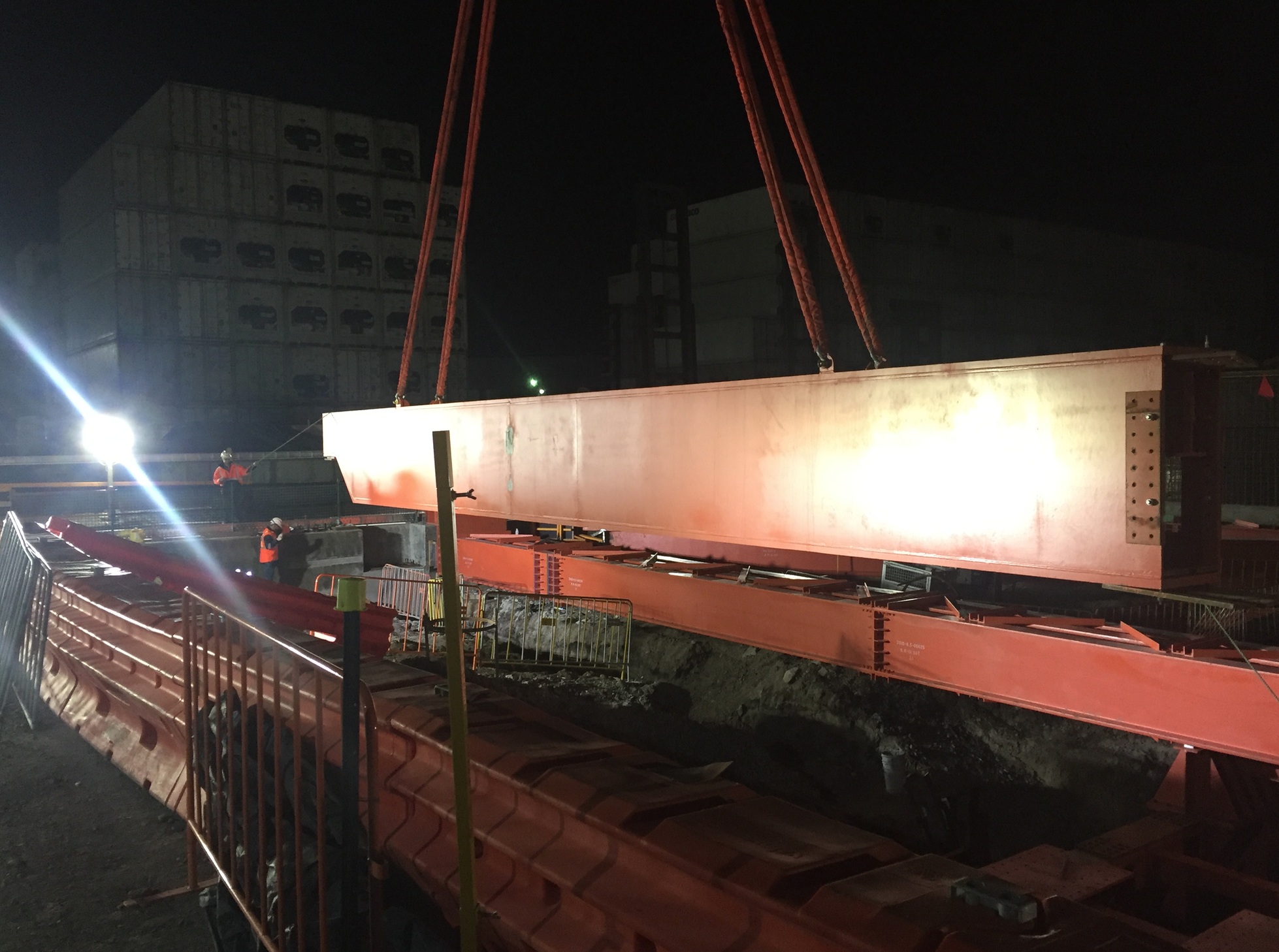
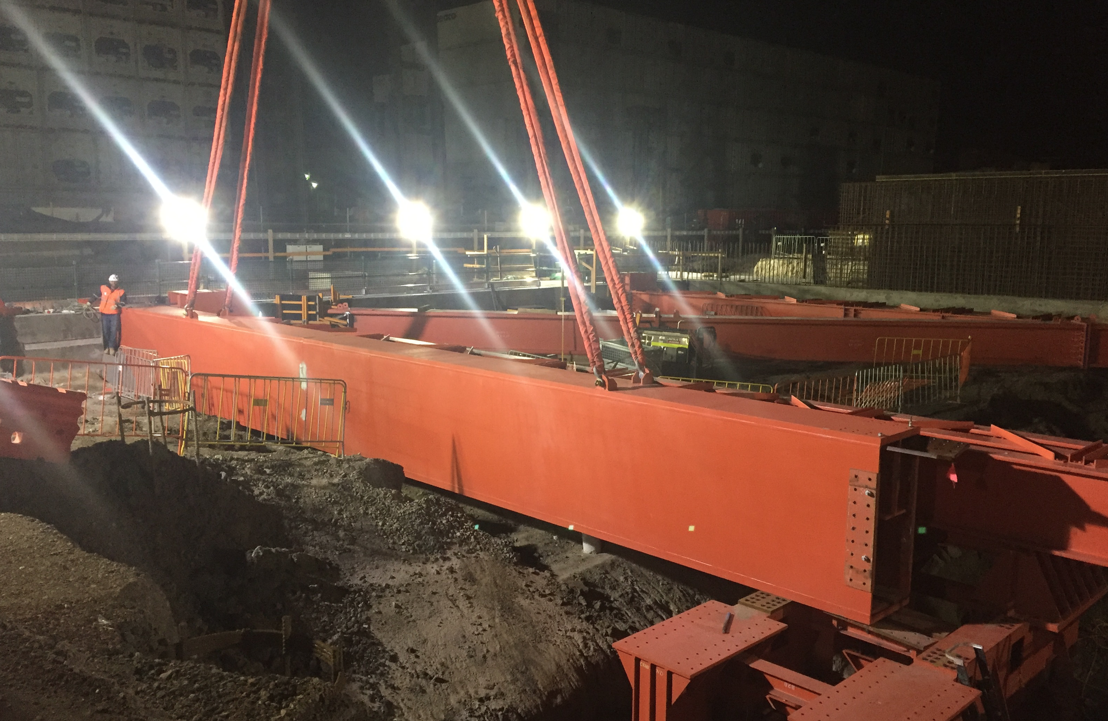
Fig. 3 Gantry crane beam install
As part of our other works the crew were also busy prepping the bearing plate on the opposite capping beam and the second section of gantry crane beam was due to be installed the following day, once our high early strength (HES) grout had gained sufficient strength. I decided to do a couple of check measurements to see exactly how the second beam would sit and to make sure we installed the bearing plate correctly. I knew from the drawings that we were looking at around 80mm of clearance from the back of the capping beam recess, but my initial tape measurements suggested it was more like 270mm. I managed to grab the surveyors before the end of their shift and they confirmed my measurements.
Having had a discussion with the foreman, and mindful that there is a risk associated with every lift, we decided to do a dummy run of installing the second beam to see exactly how it would be positioned in relation to the capping beam and the bearing plate. Having taken some photos when the beam was flush against the first section, it was evident that the “shoe” on the bottom of the gantry beam extended some 20mm beyond the edge of the capping beam, 195mm short of where it needed to sit on the bearing plate as outlined below.


Fig 6. Location of beam in relation to capping beam recess and bearing plate
This news was not very well received in the morning and the issue appears to be the result of the the gantry beam design not being reconciled with the wider cut and cover design, though the senior project engineers are being a bit cagey with the information on this…
Clearly some remediation works is required and I suggest there might be two ways forward;
- Remediate the capping beam.
- Break back the concrete in and around the recess.
- Tie in to the reinforcement and extend the capping slightly to give enough bearing for the gantry beam.
- Fabricate an intermediate section of gantry beam.
- Install the gantry beam so that it has the necessary bearing on the existing capping beam.
- Get an intermediate section fabricated to fill the gap between beams. (a rail will run on top of the beams so potentially a ~200mm gap not too hard to bridge?)
- Get new splice plates fabricated to extend across the gap in the beams
(Note: the design of the bearing plate means that relocating the one already installed would not be sufficient to fix the problem)
My initial thoughts are that to remediate the capping beam would be too complicated with potential issues due to the fact that the load on the beam may be supported partly on a cantilever and not transferred through the capping beam directly onto the piles below.
Fabricating an intermediary section with new splice plates seems like it might be a more viable option.
Thoughts from the wider forum?
The Chosen Solution
So in the end despite my cynicism, it would appear that the error in fabrication length of the gantry beam was not related to the engineering team and the blame lies with the steel fabricator in Singapore. The team did not want to draw attention to the issue so that a speedy resolution could be found on site with the upper echelons of the project wading in. It was decided that the most effective way to resolve the issue was to make changes to each of the bearing plate to allow the “boot” of the gantry beam to fit. The side already installed had fabrication work done on site , while the other was sent away to a worshop;
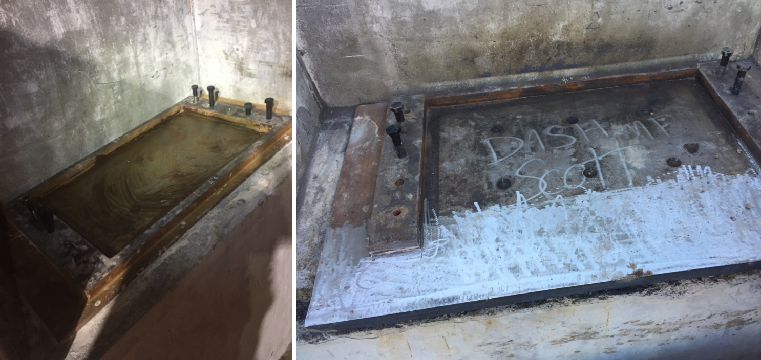
You’ll see from the image above that the front edge of the recessed plate was removed and an additional section of steel welded to the plate to bring it out level with the front edge of the capping beam. Both gantry beams have now been installed and at the headwall the excavation has reached level 2 of the props so waler brackets and walers beams are about to be installed. With only 2 weeks until the site closes for Christmas, the excavation will not reach base slab level as hoped but the engineering team are being driven hard to deliver. This is my last day on site, so unfortunately I won’t see level 2 going in.

West Gate Tunnel Project – site update
Just a quick blog to give an update on what is going on on my site at the moment as I head towards the culmination of my Ph 2 attachment.
As a reminder I am employed in the engineering team delivering the Northern Portal cut and cover structure in Melbourne from which two 16m dia TBMs will be launched early next year.
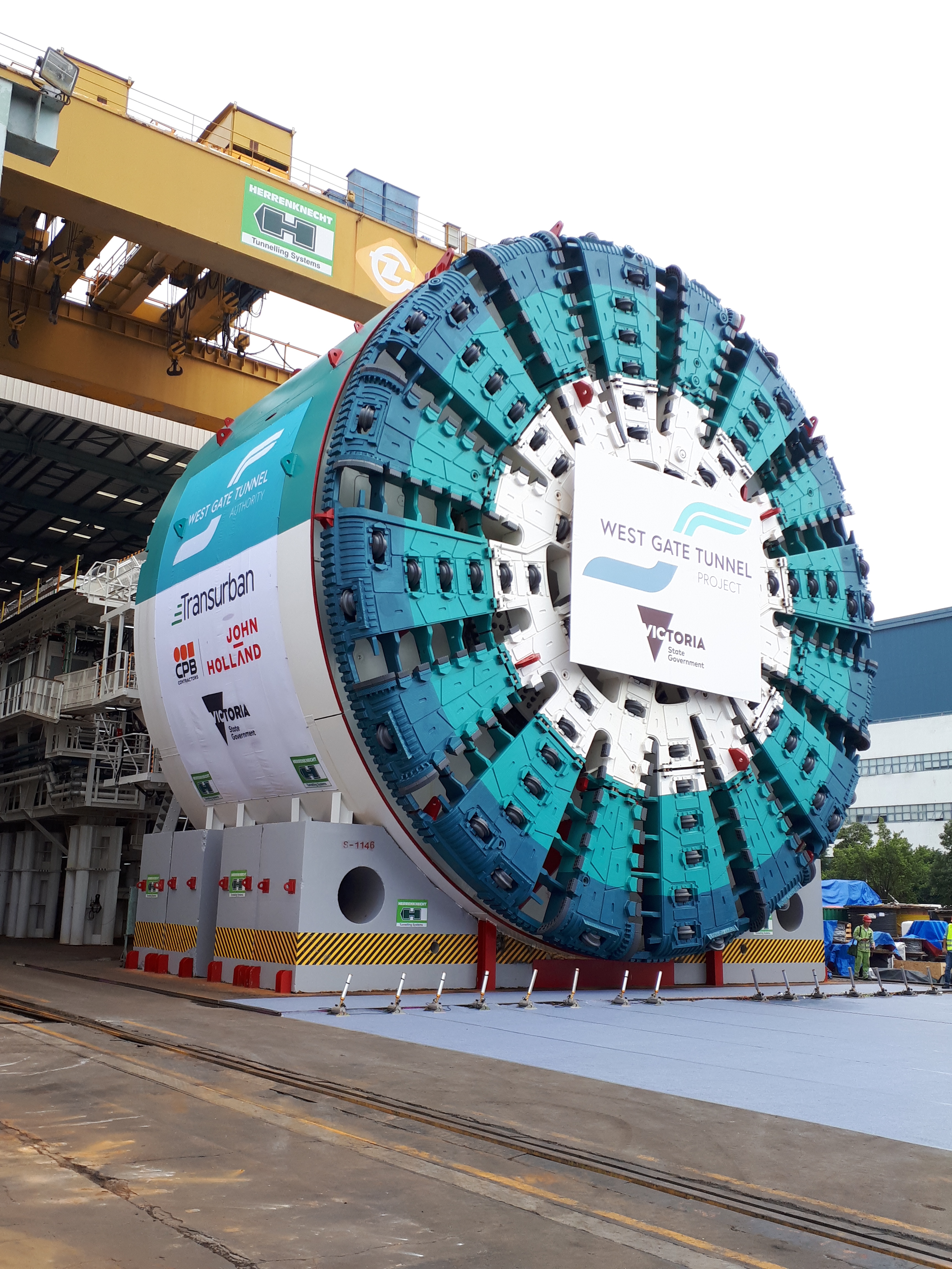
1st TBM following factory acceptance (manufactured across Europe and China)
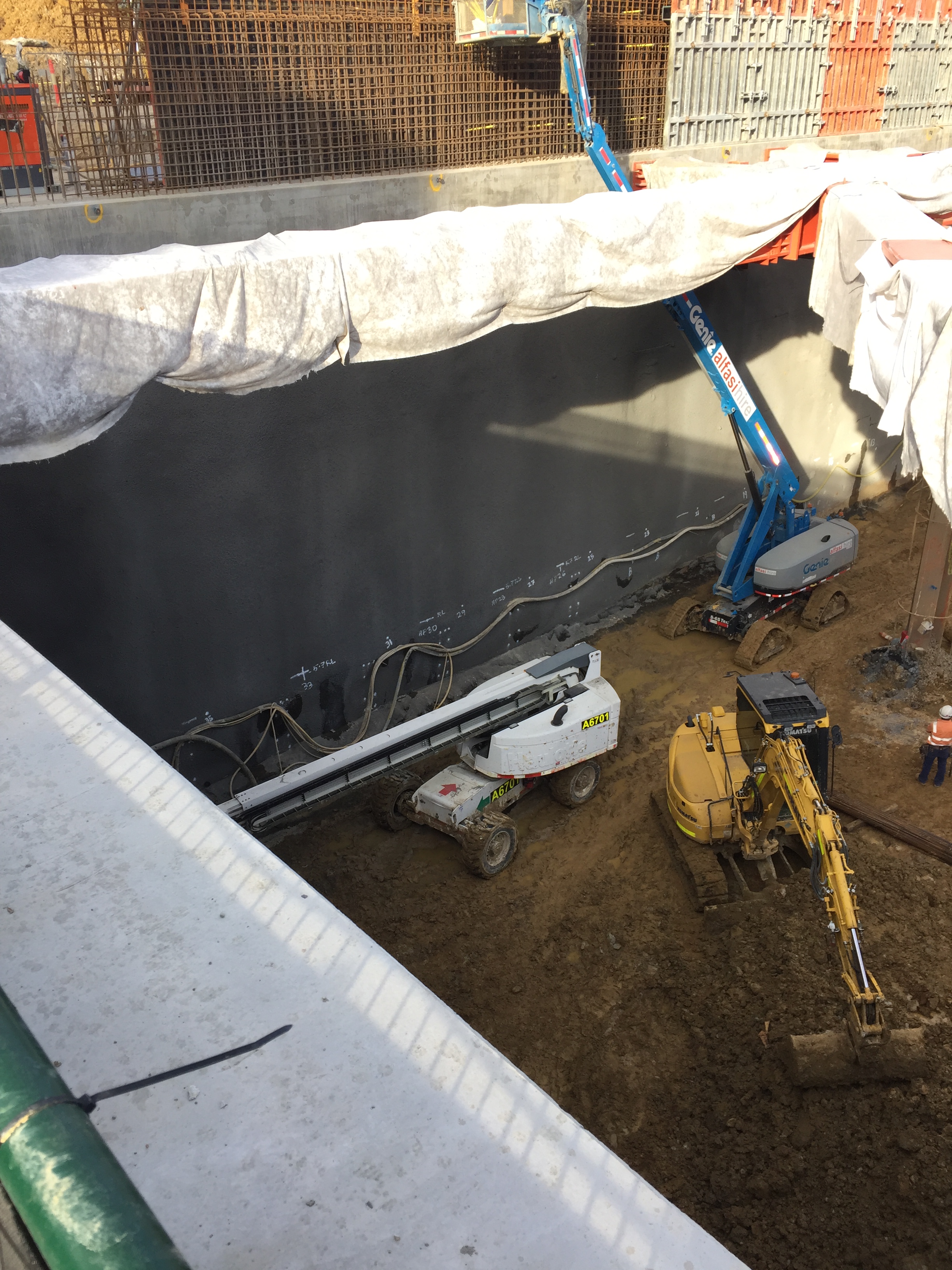
We have finally got rid of the dirty and messy piling sub contractor on site, which has opened up some real estate and allowed the installation of the temporary propping system to begin in earnest. The planning and installation of the temporary propping system has been my primary area of responsiblity and so far we have installed five 40m props across the excavation, which has allowed us to start excavating beneath “roof level”
 Having initially opted to use 35T excavators within the excavation, these have quickly been swapped out for 16T machines, due to slow productivity as a result of the machines getting bogged and the confined nature of the work area beneath the props.

16T excavators working beneath props
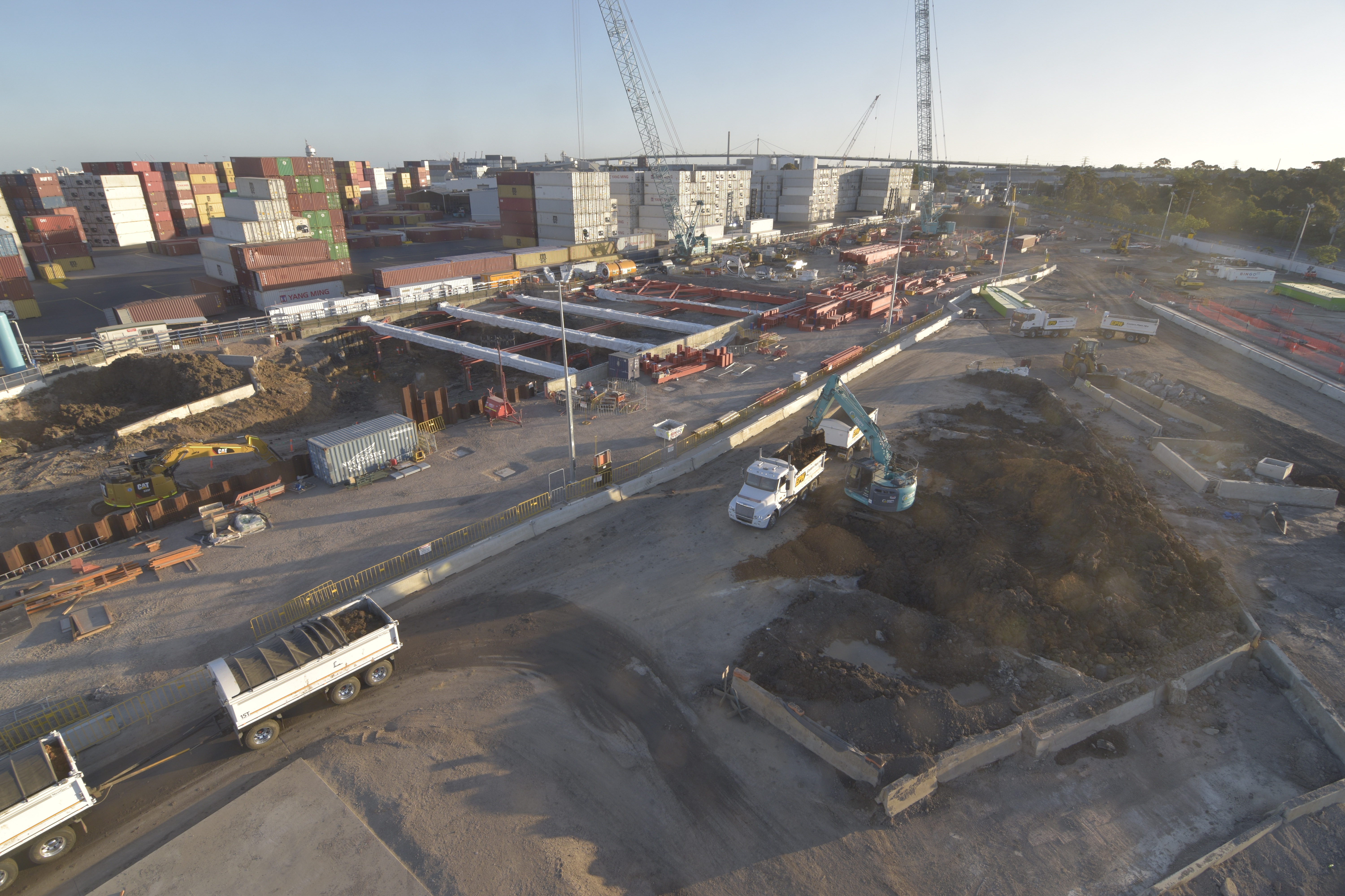
Due to hold ups in the piling works as well as changes to the design and sequencing of works (we are currently constructing using a pre-IFC design) a lot of my time is being spent managing the logistics of receiving thousands of tons of steel on site (not necessarily in quite the required order) and ensuring the sub-contractors are kept abreast of design changes and constructing to the latest design.

One of many deliveries arriving on site
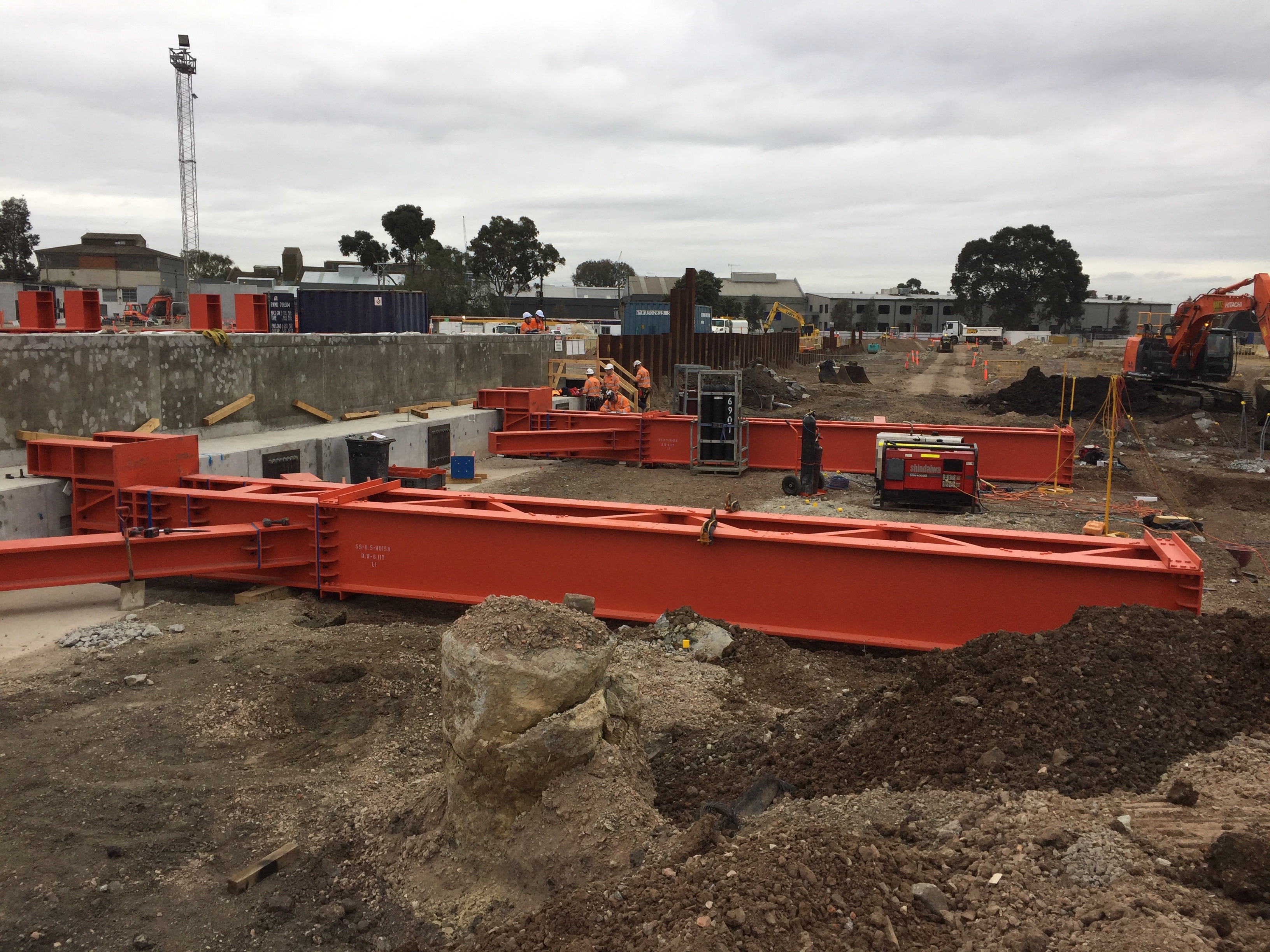
During installation of first props
During the prop installation, strain gauges are being fitted to a number of props, and settlement monitoring stations have been installed around the box, as well as prisms on the capping beam to detect any movement throughout the works.

Strain gauge installation
The data collected from these systems is monitored daily and trigger levels have been prescribed to provide alerts should unexpected movement or stresses in the props be detected. We have to submit a new permit to excavate every 24hrs which takes into account the information collected through our monitoring program.
The model below gives an indication of what the portal will look like once all three level of propping have been installed.
The TBMs are arriving in February and by that point we need to have reached full depth, poured the base slab and removed the second and third level of props, so it’s a busy run up to Christmas….
How to Splice up your life?
Just a quick post to see if anyone has a solution to the following issue which has arisen on my site, thought not in my immediate team.
BLUF: As I briefly mentioned in a previous post in order to avoid excessive wear on the TBM cutting head the designers have specified Glass Fibre Reinforced Plastic (GRP) reinforcement bars in the piles making up the head wall, through which the Tunnel Boring Machine (TBM) will eventually punch a hole. These have finally arrived following a series of delays but now there is some uncertainty on how the bars will be spliced together, as the team want to avoid the use of steel couplers.
Below is a picture of the GRP bar and the initially proposed method of using steel couplers;


My initial thoughts are that while I understand the use of GRP bars to avoid cutting through masses of steel I am surprised that relatively small gauge steel couplers will have much effect on the cutting head of a behemoth 15m dia TBM? Surely a monster of this size will just tear through the GRP bar and spit the couplers out whole at the other end?
If the couplers are likely to have a detrimental impact on the cutting teeth, then what might be a viable solution to forming a credible bond between sections of cage?
I welcome people thoughts and solutions.
UPDATE – 16/07/18
I don’t think my original description of the issue was very clear and what looks like a threaded end on the GRP bar in fig 2 might have been misleading. The bars were always going to be lapped (fig 1), but with U-bolts as seen below holding them together (I incorrectly called them couplers in the original post).
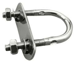
fig. 3 – U-bolt
Although these appear quite insignificant, the TBM guys have said they don’t want any steel, including these, in the piles when they cut through the head wall.
A number of possible solutions were investigated including cable ties as was suggested by Jim in the comments. However, these were deemed insufficient as the lapped connections will need to support the weight of a lower cage during installation.
Each cage is made up of two cages of around 15m in length. in the worst case loading the weight of the lower cage, 1200Kg is supported over 4 spliced connections as shown in the fig 4 below;
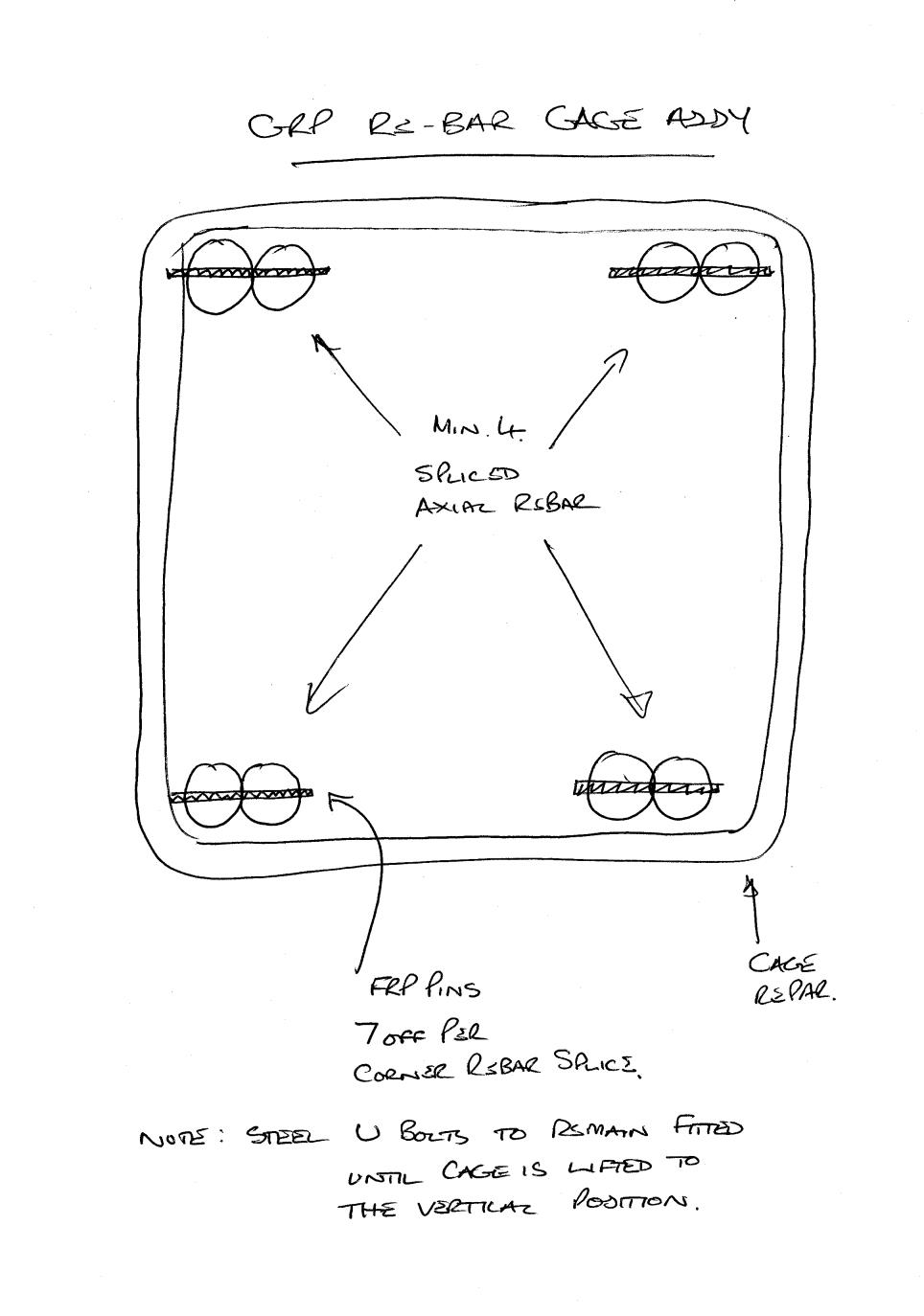
fig 4 – cage cross section
The solution that was put forward and adopted was to drill and fix 7 GRP pins through both GRP bars at each of the splice locations as outlined in fig 5.
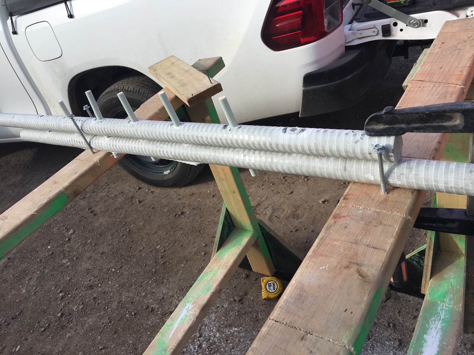
fig 5 – proposed solution
In order to adopt this as a solution, the connection had to put forward for testing to check that the strength of the connection was sufficient. The test load was based on the following;
- 1200Kg/4 splices -> 300kg per splice -> design load = 3000N
- Load test to 3000N and hold for 5 min
- Load test to 7500N (2.5 x design load) and hold for 5 min
- load test splice to failure (hopefully achieving 5 x design load, 15000N)
the image below shows the testing rig that was adopted by the lab;
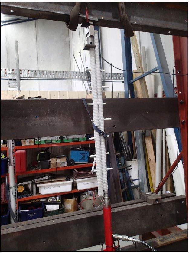
The test was repeated three time on the test pieces and yielded positive results with each test reaching 1500Kg with no defects, defections or cracking observed. This has now been adopted as the preferred solution.
Saving “Piles” of cash
While not something I am directly involved with on my site, I came across this method being used in the dressing of pile cages in a bid to save both money and time further down the line and thought it was worthy of a quick post.
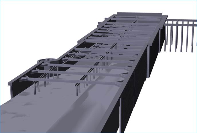
The works here on the North Portal includes the construction of a “waterproof box” inside which the two Tunnel Boring Machines (TBMs) will be built and launched, followed by further construction to complete the portal structure to its final glory as depicted in Fig 1.

Fig 1. Artist Impression of the North Portal
In broad outline we are installing a Continuous Flight Auger (CFA)/bored secant pile horseshoe and then excavating to ~20m before pouring a base-slab to key in with the pile wall to provide that box which will hopefully keep the water out. (The open end of the horse shoe is to be closed off by means of a grout curtain, or using cutter soil mixing (CSM))
In order to facilitate that connection between base slab and wall, deal with uplift and ensure a waterproof structure, couplers are being installed in the secant pile cages to allow the tie in of rebar once we get to depth, see Fig 2.
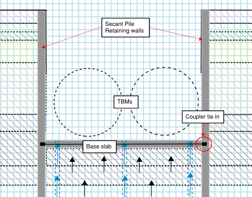
Fig 2. Pile wall/base slab tie in (Auggy, age 5)
The 40mm bar and coupler can be seen below as well as the setting within the reinforcement cages;


This might be how the cage is traditionally dressed before being set in the pile. The fun then begins once the excavation has reached depth and the couplers need to be located prior to establishing the base slab. Reminiscent of a game of pin the tail on the donkey, locating the couplers can be quite tricky, see Fig 5, and the hydro-demolition technique used quite expensive.
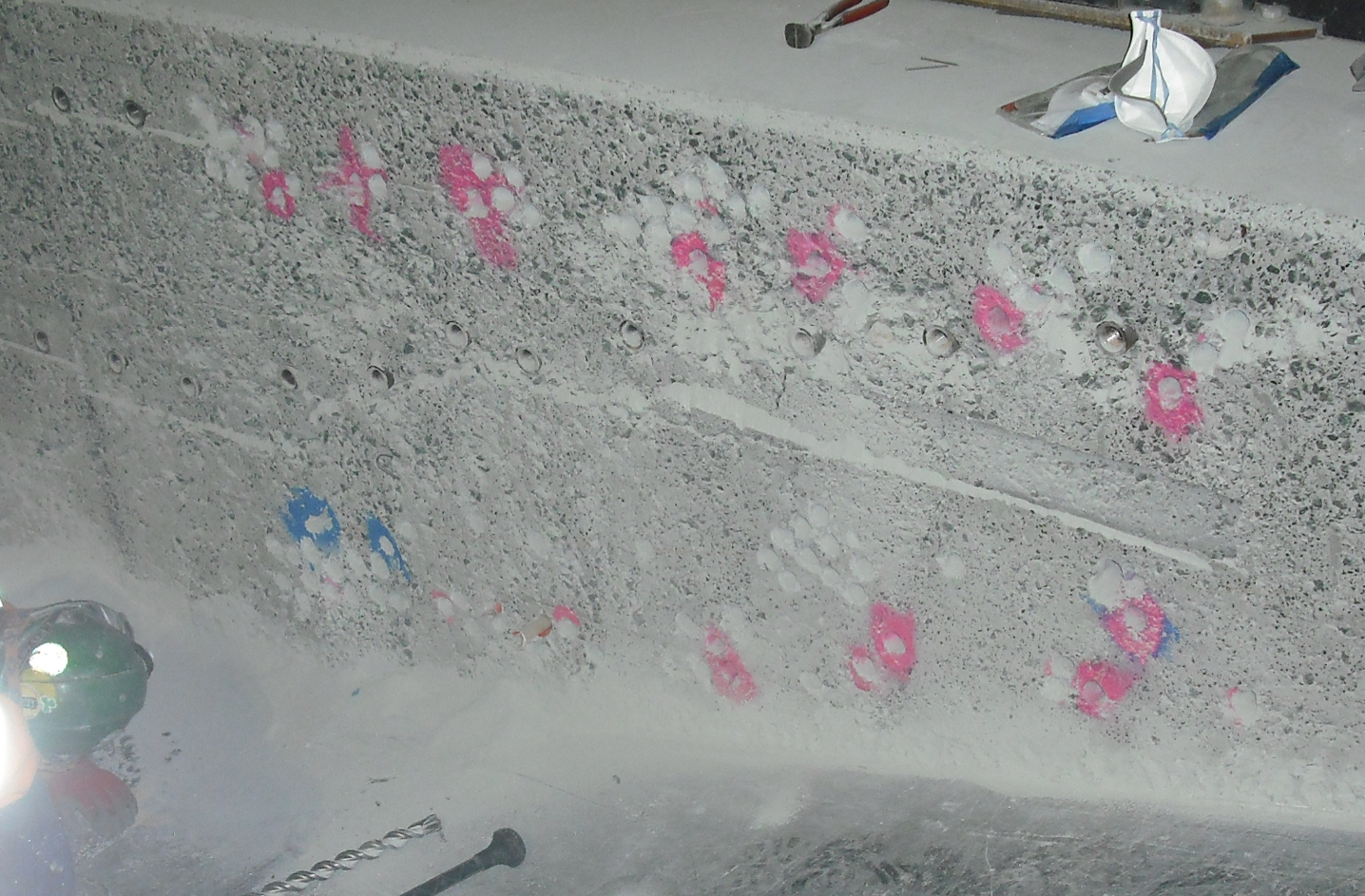
Fig 5. Find the Coupler
In order to avoid this the piling team have decided to used polystyrene and plywood to block out the area of the pile around the coupler. Adding a little bit of extra faff to the dressing of the cages will hopefully pay dividends when we get to depth in the excavation.
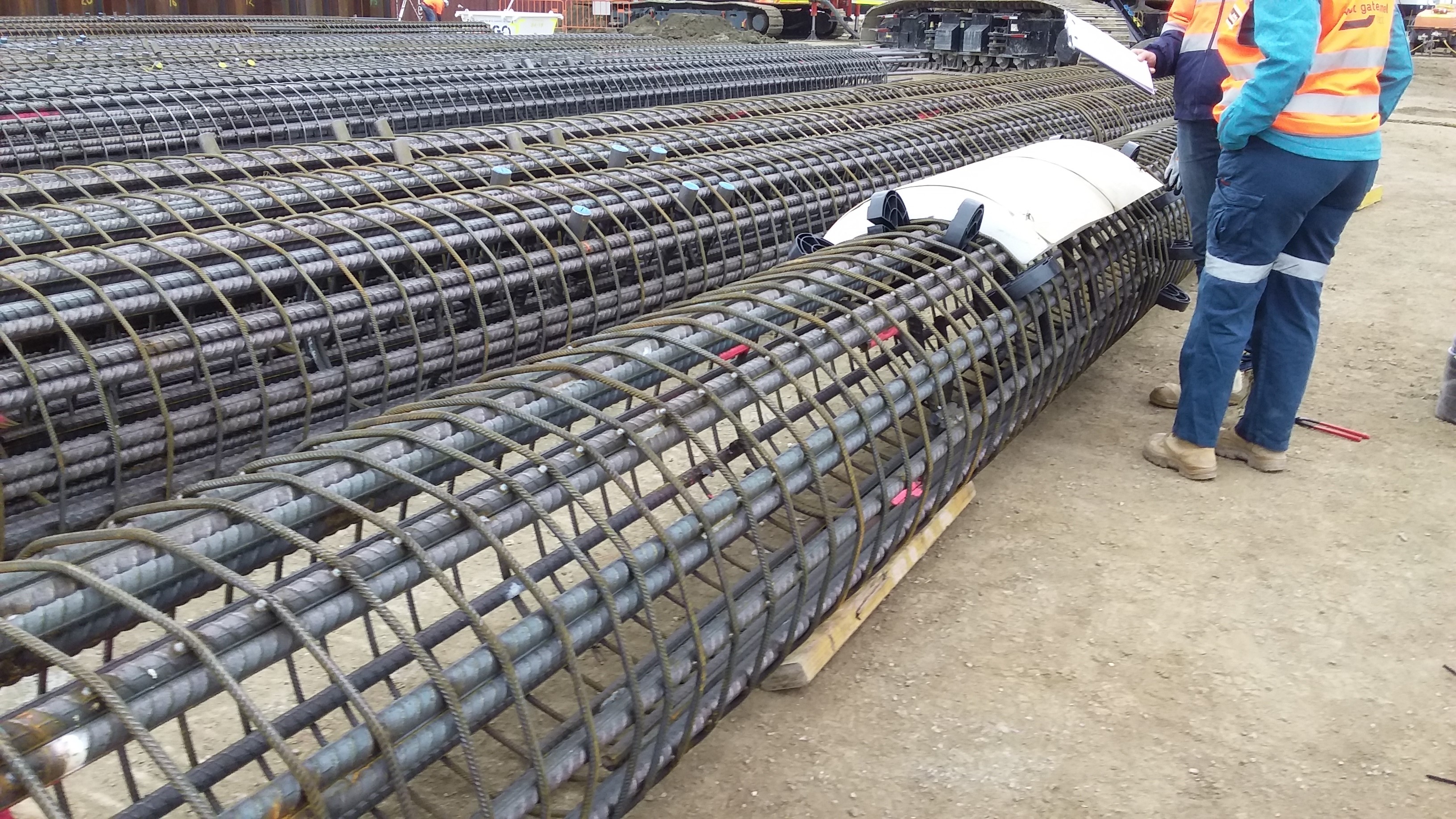
Fig. 6 Dressed cage


I will let you know how it goes. Hopefully interesting and maybe useful for some, though I’m sure it is not the first time it has been done.
* On a side note the piles going in at the headwall of the portal are using Glass Reinforced Plastic (GRP) instead of steel reinforcement. This is to avoid unnecessary wear on the TBM cutting heads before they even start! (I hadn’t heard of that being done before)
West Gate Tunnel Project – Introduction

- Fig 1. WGTP Artist Impression
Intro
I have been on the West Gate Tunnel Project now for a little under a month. A $6.7 Billion dollar project, it has been designed to relieve pressure on the existing western road network as Melbourne continues to grow and infrastructure begins to feel the pinch.
A huge undertaking, the project has been awarded as a Fixed Price, Design and Construct (DC) JV between CPB and John Holland (CPBJH). CPB are currently the leading civil engineering company in Australia and JH also continue to feature as a major player.
Laydown
With an array of civil engineering works spread over ~14Km the project has been split into 3 discreet zones, West, Tunnel and East as can be seen in Fig. 2;

Fig 2. WGTP Zone Breakdown
Each zone loosely consists of the following works;
West – The West Zone incorporates the existing West Gate Freeway, which provides primary access to the city for all traffic from the west. Despite four lanes in either direction it is routinely subject to significant congestion. Accidents along this arterial route can all but cut off access to/from the West of the city. This accident rate and congestion along the freeway is exacerbated by traffic continuously weaving and merging along the route. As part of the project an additional two lanes will be added in either direction and “express lanes” segregated to improve the flow of traffic in/out of the city. Work in this zone is significantly complicated by restrictions imposed by the Victorian Government on lane closures throughout construction.
Tunnel – The Tunnel Zone, lying in the centre of the project bounds, is the first to see significant works. It will consist of twin tunnels of 2.8Km and 4Km respectively, which will be bored from North to South to draw traffic underground and away from residential areas (particularly HGVs). Work is currently underway in constructing the Northern Portal from where the two Tunnel Boring Machines (TBMs) will be launched. These are currently being manufactured in Germany and with a diameter of 15m, they will be the largest TBMs ever used in the Southern Hemisphere. Once here they will have to cope with some difficult ground conditions and the cutting head will often be cutting across a mix of different strata. Fig 3. shows a geological profile at the Northern Portal site. Behind the TBMs a mobile factory will place pre-cast concrete tunnel section to complete the structure.
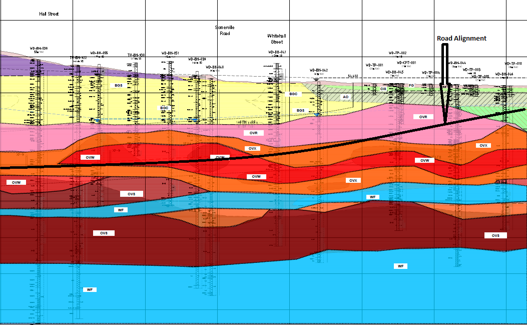
Fig 3. Geological Profile @ Northern Portal

Fig 4. Geological Profile Key
East – The East Zone of the project will serve as a link from the Tunnel Zone to the Central Business District (CBD) and CityLink, the main arterial route leading North of the city and to the airport. It will consist of a bridge across the Maribyrnong River as well as extensive sections of elevated roadway linking into the heart of the city. Featuring in the latter stages of the programme, the complexity involved in the delivery of these works has been identified as a key risk to successful delivery of the project and a new package manager, recently employed on the Queensferry Crossing in Scotland, has been appointed to review the package in its entirety.
Additional to the construction zones, the project will also be running its own pre-cast yard, to produce the vast quantities of pre-cast elements require across the Tunnel Zone, as well as in the East Zone.
Role
I have now been appointed as a Project Engineer to the Northern Portal Team, who are responsible for the bottom up construction of the portal structure. At present we are focussed on delivery of the bare portal structure within which the TBMs will be built ready to begin their journey underground. This temporary/permanent structure will take the form of a secant piled “horseshoe” which incorporates fibre glass reinforced piles at the portal headwall to allow the TBMs to break through. Once excavated a base slab will be poured over numerous tension piles on which the TBM will be built. The ~40m wide box requires significant temporary propping during excavation and I am currently developing the scope of work for its placement and removal. Fig 5/6. details the general propping arrangement at roof level, while Fig 7. give a view of the section at the headwall.
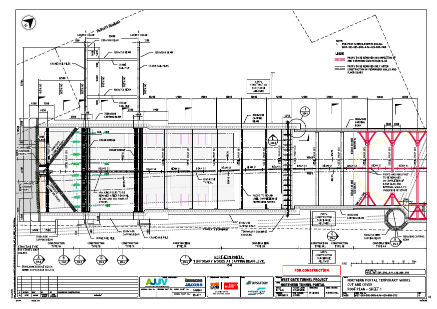
Fig. 5 Cut and Cover Roof Plan
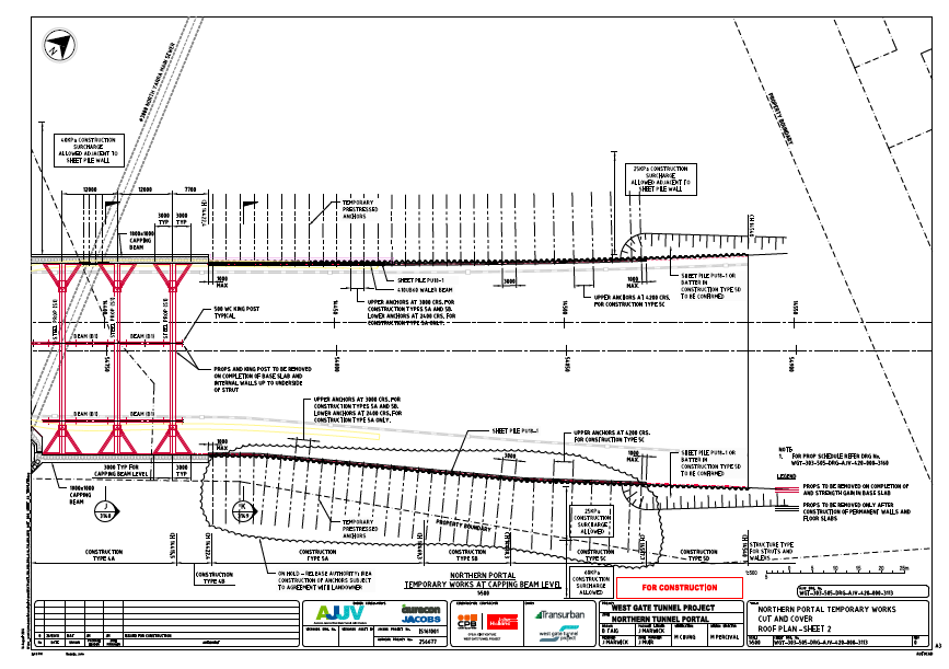
Fig 6. Cut and Cover Roof Plan 2
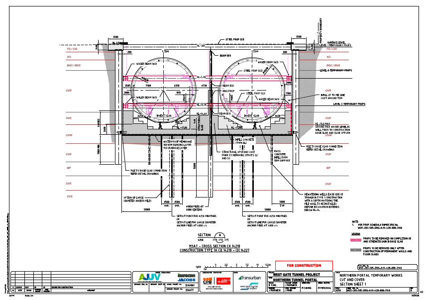
Fig 7. Northern Portal Section
Summary
There are certainly a lot of aspects to this project to capture my interest and I am sure in my relatively short time here I will be exposed to some of the challenges faced in delivering major civil infrastructure.
A couple of areas I might look at blogging about in the future or incorporating in AERs/TMRs are;
- Geotechnical Design/Challenges
- Approach to dealing with groundwater
- Diversity Employment targets
- Management structure on large scale infrastructure projects.
