Archive
What’s a TMR? – Traditional Vs. Whole Footprint Jump Form
Hello all,
It’s been a little while since I posted and I also realised I failed to follow through on my promise to add more information from my previous post ‘Innovative Jump Form System for the Residential Tower’ if you’ve not read that one feel free to check it out.
With the deployment of the junior course and what must be the impending deadline of submitting TMR 1, I though this blog might kill two birds with one stone and not take me too much time doing it.
- It might provide some insight on how someone has formatted and worded a TMR. This is by no means ‘the’ way of doing it its just ‘my’ way but it has severed to get me though with reasonable marks. I know how hard it was to get into the swing of TMRs especially setting up how you want them to look and feel.
- The topic of the TMR is a comparison of a traditional jump form system with the new style whole footprint system deployed on my site during my Phase 2. I managed to get myself a role as the Site Engineer for vertical elements and so was working with it daily. Thus this fulfils my previous promise.
At this LINK is the TMR itself along with the supporting Annex’s. I have also put in John’s comments and feedback following my submission so you can see the areas I could have improved, I have removed the marks suffice to say it scored over 50%.
Happy to answer any questions or comments if anyone has any. Hopefully this is useful to someone and doesn’t come across as self serving, believe me that is not my intent.
Concrete Quality: How Bad Can It Get Before Structural Compromise?
Hello all,
Just a quick one to spark some debate and follows on from Ed’s the other day. I have been involved with the vertical elements of my project site which include columns and outrigger core walls. The pours have been going well but on opening the forms up today a number of elements have had issues. Multiplex have referred these issues to the consulting engineers and are waiting on their response for the required remedial action or acceptance as they see fit. Some of the elements where poured on different days using a mixture of kibbling and pumping. All are 80mpa which generally is being reached well before the 28 day mark with the columns feelably hot. The mix is designed to be self compacting with no requirement for vibration but the supplier has been having issues with producing consistently accurate mixes. These elements are on level 7 of 82.
Column 1 – Evidence of very small honeycombing and cold pour joints
I would suggest that no rectification is required for this column. Your thoughts?
Column 6 – Evidence of small honeycombing and cold pour joints
Again I would suggest that no rectification is required for this column. Your thoughts?
Column 7 – Evidence of cold pour joints and large scale honeycombing which is exposing reinforcement.
My feeling on this one is that rectification will be required. I think that as a minimum they will ask for the concrete to patched to cover over the steel work but that more extreme remediation could well be asked for.
Column 10 & Outrigger Core Wall 8 – Evidence of small honeycombing and cold pour joints isolated to a single batch of concrete. This was kibbled and you can clearly see the flow of concrete away from the column, which was the insertion point, into the rest of the wall.
As before I would suggest that no rectification is required for this column. Your thoughts?
Multiplex should be getting the consultants response shortly so I will update the post with this detail once received and you will be able to compare your thoughts to that of what actually happened.
Innovative Jump Form System for the Residential Tower
I have recently completed the area I was first working on and have now been assigned as the Site Engineer for vertical elements in the just started Residential Tower. From my first blog you would have seen Multiplex (MPX) fears over not winning this job and the congestion on site that would have caused. Well they needn’t have worried as they won the contract and have just started construction of the 80 story Residential Tower.
The system of jump form that has been selected is causing some excitement in the office, so I thought it was worth sharing with you here. It is apparently so innovative that most in the office have never even heard of it let alone seen it. Before we look at the new system it is worth just understanding how a traditional jump form works.
Traditional Jump Form Tower Construction
Traditional jump form systems form the core only, several levels higher that the decks. The video below shows the normal sequence for a core only jump form.
The foot print of the jump is normally only a fraction of the buildings and space is very tight at the top. Below is done pictures of the traditional jump system being used for the commercial tower on my site.
The decks are then constructed using either structural form work (i.e. bondeck which provides form work initially and then becomes part of a composite slab once the concrete has cured) or traditionally using removable form work that is supported by a lattice of props and beams. Critically this leaves the columns to be poured separately once the deck is in place. Again this is normally done using a traditional form which must be set up individually for each column adding days of delay. To get around this on the commercial tower on my site are using hollow steel sections as form work then pouring concrete into them to create a composite section. Below is some more pictures of the commercial tower this time of the the decks being constructed.
Oliver Moore (OM) Jump Form Tower Construction
This new OM jump form is radically different in that it covers the whole footprint of the building and allows the construction of all vertical elements simultaneously and at the same level i.e. the core, columns and shear walls all done at the same time and same level. When fully constructed the system also contains all structural and external façade works minimising the risk to workers and the general public. This is achieved by having a set of screens directly attached to the top of the jump which hang down 5 levels to enclose the horizontal structural works (in this case PT slabs).
From the bottom of the first screens a monorail system is connected which allows a winch system to manoeuvre around the whole of the building for façade install. This eliminates the risky use of mini crawler cranes that have to dangle massive glass panels over the buildings edge to get them installed. These works are similarly enclosed by a second screen system cantilevered from the first hanging down 2 levels. The connection to the primary jump system means both screens and monorail will move as the system does. When this happens an externally complete building will emerge from out of the bottom of the jump.
Multiplex have set an ambitious completion program that has been written into the contract. Once fully launched the jump has been set a 5 day cycle which means all steel work will have to be completed in 8 hours and post tensioning work completed in 4. I have yet to dig in to the program so don’t ask too many questions on this just yet.
The new jump system is also getting an extensive vertical transport system to support the cycle time. The movement of men and materials will be supported through a number of systems, three high-speed site hoists will be installed along with two tower cranes and an integral cantilevered jump lift. A single car site hoist will move through penetrations left open in the podium slabs before climbing the exterior while a double car site lift on the other side of the building will climb up the exterior of the tower from ground level. These hoists will be extended in line with the jumps to ensure quick access is always maintained to the top of the jump form. There is also a cantilevered integral materials lift that is connected to the jump system moving as it does, the lift will be used for the movement of materials up to 5 levels down from the top deck. This is needed as normally the cranes would land materials directly on the decks but with the jump system covering the decks materials must be landed on the decks and subsequently transported down.
This is all shown diagrammatically in the images below however I suspect they won’t come up large enough to see the detail, so please click here to access the source documents.
Hopefully that has been interesting and provided a snap shot of what I am up to. Please feel free to fire any questions you have at me and I’ll do my best to answer them. The jump isn’t on site yet so I’ll probably follow this post up in a few months once it’s running to give you some real pictures and let you know how it works in reality.
Aconex a Powerful Project Management Tool or Expensive Email and File Server?
Hello all,
For TMR 1 I am writing on the use of digital project management and communication systems as I have seen them in Multiplex compared to how a “power user” would use them compared to how I have seen/done project management and communication in the military.
To give a very quick overview if you have no idea what I’m taking about, Multiplex uses a system called Aconex which is a cloud based project management system providing a full audit trail across all project stakeholders. Once anything has been uploaded or sent it is there as a permanent record to aid in future understanding of evolution of design, contract negotiations, dispute resolutions, etc… It works fully in the cloud with only a web browser needed for access but also has powerful mobile apps which allows site based personnel to access current documents, send RFIs, log defects and respond to/create messages.
Aconex have a short sales video which describes what they do far better than I can in this very short blog, which hopefully works below.
What I don’t know is what other systems are out there and what the UK construction industry uses, so I’m asking for your help. In the comments below could I get you to let me know what systems your projects are using and give me an idea on how they are being used. Thanks all.
Once complete I will put up a summary of my TMR so you can see what my conclusion was and if there is utility for future military projects we will be involved in.
300 George Street Site Introduction
Hello all no technical content in this blog just a quick project overview and introduction to my site, future posts will outline specific issues etc. that come up. I won’t dwell on the admin and challenges of actually getting out here suffice to say the “Beast from the East” couldn’t have chosen a less opportune time to hit the UK. My thanks to all who helped pick up the pieces of my carefully laid plans.
Location:
300 George Street is located in the heart of the Central Business District (CBD) in Brisbane Australia. It is a whole city centre block redevelopment tightly boarded by four busy lanes of traffic with the Brisbane River running just to its South West.

Figure 1 – Site Location
The project:
I am attached to Multiplex on the 300 George Street Project site in the heart of the Central Business District, Brisbane, Australia. The site is large vertically but takes up only a single city block approximately 100x80m. The project consists of a 3 floor retail/hotel podium above ground that links three separate towers; hotel; commercial; residential as shown by Figure 2&3 below.
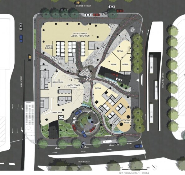
Figure 2 – Artists impression plan view of project showing the different sectors on the final construction.
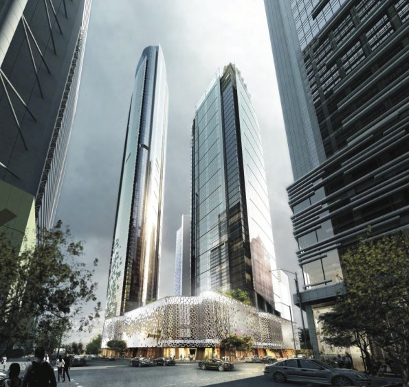
Figure 3 – Artists impression of completed structure from the corner of George & Adelaide Street. Residential tower to the left, Commercial tower to the right and Hotel tower to the rear.
Tower 1 – Hotel:
Tower one is the 34 floor luxury W Hotel complete with conference, spa and gym facilities. It is structurally complete with its final stage of E&M fit out well underway, the first levels are due to be handed over by the end of the month with the hotel set to open its doors around 1 June 2018. The internal finish is very impressive and it is clear the hotel is set to be a very high quality 5 star establishment.
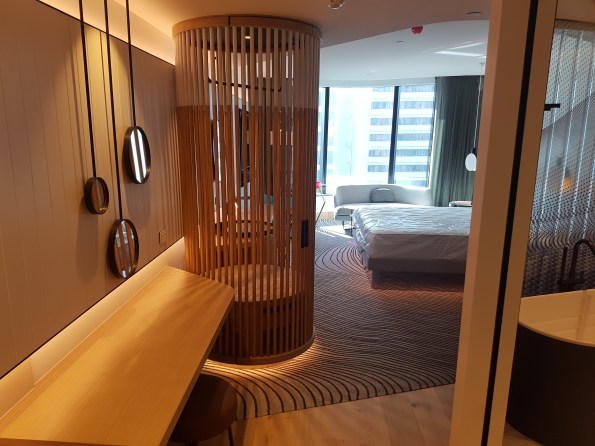
Figure 4 – The inside of one of the completed “basic” rooms, curtains, lights and sound system all electronically controlled from pads set into the walls.
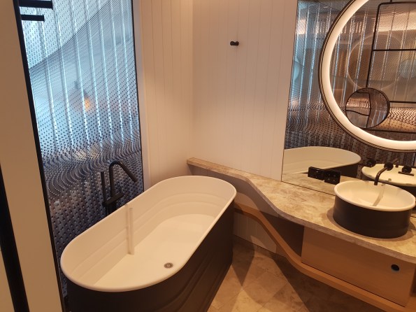
Figure 5 – Standard bathroom, shower and toilet to the right out of shot.
Tower 2 – Commercial:
Tower two will be a 40 floor commercial tower which will house a number of office spaces. Its superstructure is still being formed with a traditional slip formed core up to level 18 and decks to a few levels below this.
Tower 3 – Residential:
Tower three will be an 82 floor luxury residential tower however for now it is just a small concrete core barely sticking up out of the top of the podium. Work has yet to start on this tower due to the way the client has chosen to stage and let the contracts for the site. Multiplex are currently tendering for the contract to build this tower with the announcement due to be made shortly. There is clearly no guaranty they will win it and this possibility is causing some angsts due to the possibility of having to fit another primary contractor onto an already heavily congested site. Should Multiplex win the contract they are proposing a non-traditional method of construction that will supposedly see the core and decks being formed simultaneously. Figure 6 shows the current state of construction for the various areas.
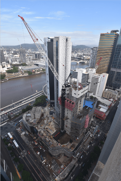
Figure 6 – Construction progress as at 21/03/2018 viewed from above the corner of Adelaide Street (perpendicular to river) and George Street (parallel to river). Hotel tower complete bar cladding in the rear, Commercial tower being slip formed and decked to the right, Residential tower not yet started but the start of the core visible to the left.
Basements:
Figure 7 shows that below ground 7 levels of basement have already been completed and partially handed over. This area is comprised of car parks, hotel back of house facilities and services/plant rooms.
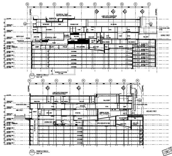
Figure 7 – Construction drawings showing two sections through the Podium and Basement.
Conclution:
Hopefully this has been of some interest in terms of base lining my site. I think the site is an interesting one and should provide plenty of opportunity to gain experience. I already have some ideas for future posts/AER/TMRs as time allows:
– Australian approach to H&S
– Digital document management
