Archive
Phase 3 – getting the geek on!!
Hi all,
Merry Christmas, I trust like me everyone had intentions to do loads of thesis but ended up doing none.
Getting a little bored of working for a management contractor I decided to move to phase 3 mid November. I though now would be a good time to give a little update.
I’ve started at a small office which have recently branched out from Australia into the London market called BG&E. I haven’t yet worked out what that stands for, for those interested here is the website.
There are 9 in the office, 4 structural engineers, 1 BIM technician, 1 CAD technician, 2 RC detailers and me. So far the office has been doing temporary works for some of the big London contractors and some mid rise residential developments in Cyprus.
Since starting, I have been getting bits of work but as can be expected nothing substantial. I’ve outlined what type of stuff I’ve been doing.
Task 1 – Reinforcement rates
Part of a wider package with Getjar, as a second checker I used a mixture of RC intents and details to calculate tonnages for costing as part of a tender return.
Task 2 – Transfer Beams
The Broadway, London is a resi/commercial development with 6 buildings between 14 – 20 stories. The structural engineers, RBG, have detailed a steel section encased in RC as a transfer structure for a line of columns which go the hight of the structure. The step that the beams make is an architectural feature of the building creating large lobbies, see the section through below.
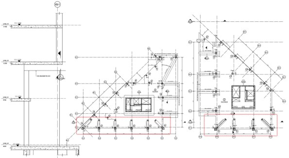
The issue was the contractors crane strategy did not have the lift capacity/radius to lift in the transfer beams. So they engages BG&E to conduct an option study, which was then given to me. There was no information on column loads, just the GAs and floor load diagrams. Unfortunately for me, the column tributary areas are different for each column and also the loads. So I did a column run-down using load reduction permitted in EC1 to get the loads at the base of the supported column. I then used a software called RAPT to ‘play’ with possible options. The most effective solution would have been to increase the depth of the beam and use normal reinforcement, however generally beams cannot be increased in depth due to the other trades. So I increased the width of the beam to 1200mm and it worked with 3 layers of 32s @ 100 (in the bottom), this was proposed to the contractor and we wait for further work. Clearly PT could have been used, but the it is not clear if the floor plates will be PT as they are c300-350mm which is thick for the spans.
Task 3 – Climbing Screens
Wembley Park, is a large resi development to the left of Wembley Stadium for those who have been recently. The contractor has won the job and is trying to work out their climbing screen and back propping strategy, the climbing screens can be seen below. This seems a little late to me, how much floor back propping is required and how quickly it can be struck must surely be known to form a programme. Unless it is a guess….
Getjar ask BG&E to conduct a concept study to see what is required for the climbing screens. Again the RC intent was not available as the design is not that advanced, all that was available was the floor plans and loading diagrams. Looking at the typical floor layout it was clear that there were three different spans. Knowing that the RC slabs would be designed for the loads in the diagrams, i.e. permanent case. I built the spans in RAPT (programme) and calculated the forces and reinforcement required. I then used this to compare to the construction case with the loading from back propping, climbing screens and a construction LL.
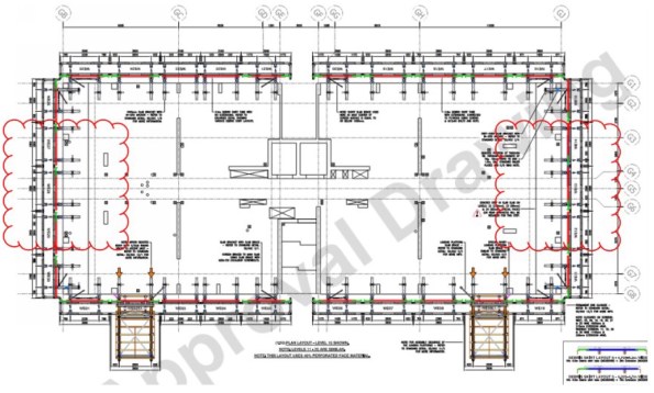
This showed that the climbing screens did not need any additional back propping, if the loads where not applied at the same times as the back propping to construct the wet deck. This is unlikely, as the buildings a residential the SDL and LL are low, 1.5Kpa each. The 250mm RC slab exerts a back propping load significantly larger than this and would need back propping over at least two floors. I calculated that for the loads to be combined the reinforcement would need increasing locally by up to 15% above that required in the perm case. It is now up to Getjar to do a cost exercise, material cost v programme to see which is preferred.
As a side note I also check deflections to ensure deflections under construction loading where not excessive. Whilst doing so I noticed that one of the larger spans was deflecting 30mm under permeant loads which is over span/250, which would be bad for internal finishes. I raised this to the contractor and this may come back to BG&E to design a PT slab for this area.
Task 4 – Tower Crane Grillage Cat 3 Check
The foundations for tower cranes are generally considered temporary works and as such fall under the guidance of BS 5975. The level of the required design check is outlined generally on the complexity and consequence of a failure, the category’s can be seen below.
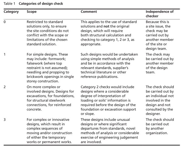
My previous project, One Nine Elms has 5 tower cranes, all supported off grillage which is more complex than normal, I have discussed one at length in a previous post. Clearly the consequence of a failure could be dire, for those with a strong stomach YouTube ‘tower crane collapse Mecca’. It is also bad for business, failures are very public affairs and to make them worst developers/main contractors like to put their company logo on the crane. Anyway, a cat 3 check should be conduct by a person outside of the organisation which did the design. The check should be done without the calculations, just the drawings and any pertinent information, loading etc etc. This task was given to me with the direction to see how far I get…… shit. I was given some information about the crane and Carey’s design drawings.
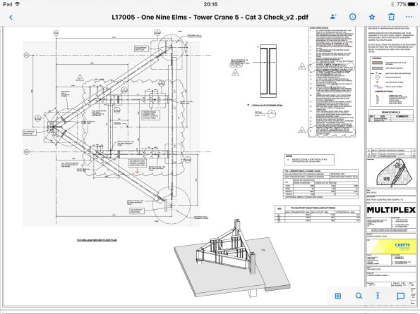
My first start was to check Carey’s had used the correct loads from the crane supplier, it was slightly concerning to find they had missed the most onerous case a storm hitting the front of the jib. I built the steel grillage in a software called Microstran (similar to STAAD) and applied the loads with a number of different combinations to get forces and deflections. I then realised I have forgotten everything Neil taught us about steel and spent a day going back through section and member checks by hand, the software also does a check which it useful. Clearly somebody sits in the crane cab so a large differential deflections between the legs gets amplified higher up. I also believe the crane suppliers factor up the loads they provide, as a way of reducing deflections to stop Pdelta effects.
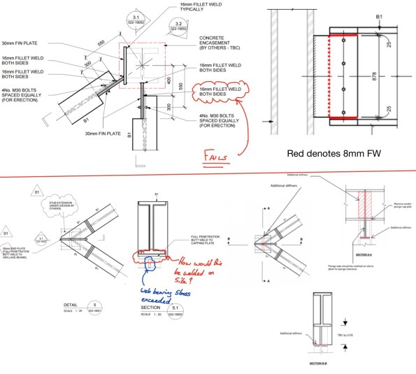
By far the most difficult check was the connections, with my main issue being whether to fix or pin the members at the joint. I found the 16mm FW on the fin plate insufficient by some margin in either case and suggested an alternative solution. The solution (see below top) uses and 8mm FW which can also be done with one pass so Saving labour costs. In checking the apex type of connection I found that the plate welded to the plunge column plate resulted in a bearing stress great than the capacity of the section and would also be difficult to weld on site. After some head scratching and advice I came to the solution below.
Quite a bit if stuff in a couple of weeks and I am learning lots quickly. One thing I have noticed is that the engineers do almost everything on some form of analysis software, Excel and Bluebeam with very little being done by hand.
I hope I haven’t bored everybody to much but you already know I’m a geek.
Brad
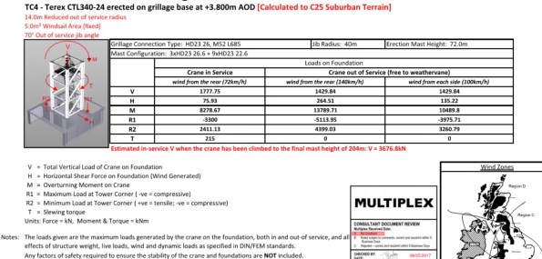
James, these are the loads supplier by Select for a 70m tower crane. The overturning moment drops to almost nothing when the crane is tied.
One Nine Elms
Hi All, It’s a long one with few pictures, but interesting……. I think.
A recent series of events on One Nine Elms has left me wondering why project managers get paid ‘the big bucks’.
A new project manager has recently started in the project team, he previously worked on the project for McGees before joining Multiplex about 2 years ago. As such he has a good understanding of the project with exception of the sewer complications. Anyway he has arrived to impress the two project directors, with his current mantra being progress at all costs, which has potentially had some significant cost implications for Multiplex.
The diaphragm wall has been constructed under a design and build contract by Balfour Beatty Ground Engineer (BBGE), who Is contracted directly to the client. The first main contractor, CI- ONE, had a traditional bottom up sequence with props below or above the permanent basement slabs. This is what the wall was originally designed and partly constructed for. Balfour Beatty then became the main contractor (on a PCSA), and they changed the methodology to top down. This different sequence was re-checked against the as built wall, with BBGE confirming the design was sufficient. When Balfour Beatty and the client were unable to agree on cost and programme, Multiplex won the subsequent re-tender on a semi-top methodology which I have mentioned in a previous blog. Crucially as MPX did not signed the head contract until July and potentially not doing an in depth review of the project risks, they recommended to the client that the new sequence be checked again, instead of spending the c£40k themselves. As a result this check only started about 6 weeks ago despite Multiplex starting on site in January.
In the meantime, Multiplex have tendered, appointed and started on site the basement box subcontractor. As a result there is significant pressure to justify the subcontractors preliminaries and see some progress, i.e. Excavation to B1 formation. Armed with the fact that AKT (structural designers) had conducted a study confirming the D Wall could cantilever from B1, the new project manager actively encouraged the basement package manager to commence excavation. At this point both the project engineer and I advised that this was unwise, BBGE had not yet ‘approved’ the new sequence and there was no deflection monitoring in place. The Project and Package Manager came back with AKT have approved the sequence and an interim monitoring package has been signed with ITM. When I said that BBGE will not give warranty on their work (c£35M) if excavation commences without the approval of the sequence, I was told not to worry about the contractual stuff.
The week before the excavation started, BBGE returned the calculations for section of Wall where excavation was planned to start. The calculations showed the wall was acceptable under ULS but not SLS. The retained soil has high sulphate content, therefore the concrete exposure class is XC3, which has a. crack width limit of 0.3mm. The new sequence SLS moments cause cracks which exceeded this (theoretically), therefore the new sequence is not acceptable to BBGE. This was known before excavation and a number of things are currently being looked at to get this cracking issue to be acceptable. Interestingly during the first sequence change, BBGE could not get the deflections within limits in their WALLAP calculations. As a result AKT modelled the basement in 3D FE and have taken responsibility for deflections, slightly worryingly BBGE deflections are an order of magnitude higher.
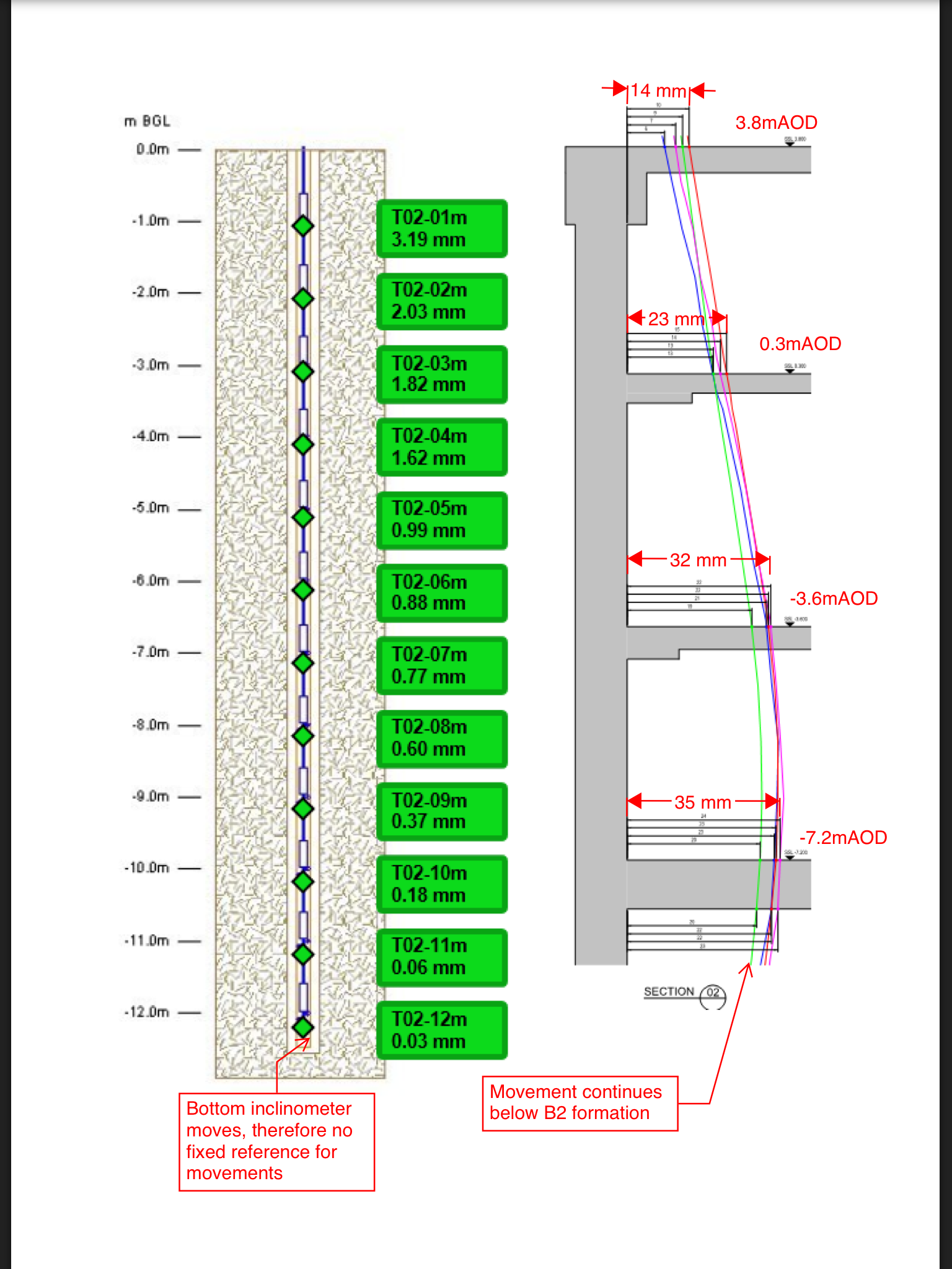
Despite this excavation commenced, with active encouragement from the project manager and construction director. With this in mind, the last thing you would want is a poor monitoring package. By chance I was asked to chair ITMs (monitoring company) pre-start meeting on behalf of the package manager, who had effectively tendered the package. It quickly became apparent that the inclinometers are not fit for purpose. They only went to B2 formation level where there would still be significant movement. This means the head of the inclinometer would need surveying manually in order to provide a reference point to baseline the inclinometer, not good for an automatic system to rely on the manual input of data to work. Furthermore it would appear that this manual reading had only been bought to be conducted once a week.
So, Multiplex have basically started excavation without approval from the designer and without any deflection monitoring in place. Low and behold, the client receives a letter from BBGE, informing them that they cannot offer warranties on their works because Multiplex have excavated not to the approved sequence and with no monitoring. The project manager and construction direction then hit the roof and basically blame the package manager, conveniently forgetting their encouragement to start excavation.
The result of this is not yet known. The two individuals had been given sound advice which they chose to ignore, they then tried to blame everyone but themselves. Poor management, decision making and leadership from individuals paid a lot to do this well.
Fellow Multiplexers don’t show this to anyone in the company.
Alway interrogate loads!
I am currently working through packaging up the loads from the Tower Cranes, which connect to the permanent structure by a steel grillage. These loads will then be checked against pile capacities. I have been embarrassed slightly but it has taught me a valuable lesson which I will explain below.
The Tower Crane strategy on a high rise structure is a key element to a tender, the number and location is picked before sub contractors are brought on board. The tendering of packages is then conducted on this number, location and a % time allocation and are therefore relatively fixed.
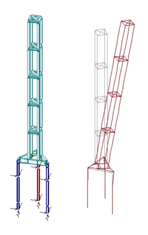
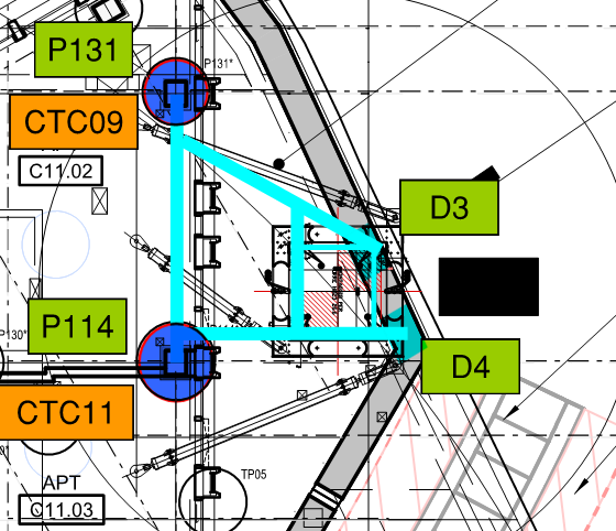
In order to be confident that the locations are feasible, MPX contracted Robert Bird Group to conduct a feasibility study which suggested a steel grillage would work in the configuration below for one of the tower cranes.
Once the basement subcontractor had been appointed (on a PCSA), they took the loads from the Crane supplier and sized the steel grillage. Now, if you imagine a 70m high free standing column, the horizontal load from wind will create a significant overturning moment. This moment along with the self weight creates large tension and compresive forces in the legs of the crane. This results in large reaction forces in the grillage supports (in this case plunge columns in piles and a diaphragm wall) and due to strict movement criteria the grillage is fabricated out of deep I Beams (large second moment of area).
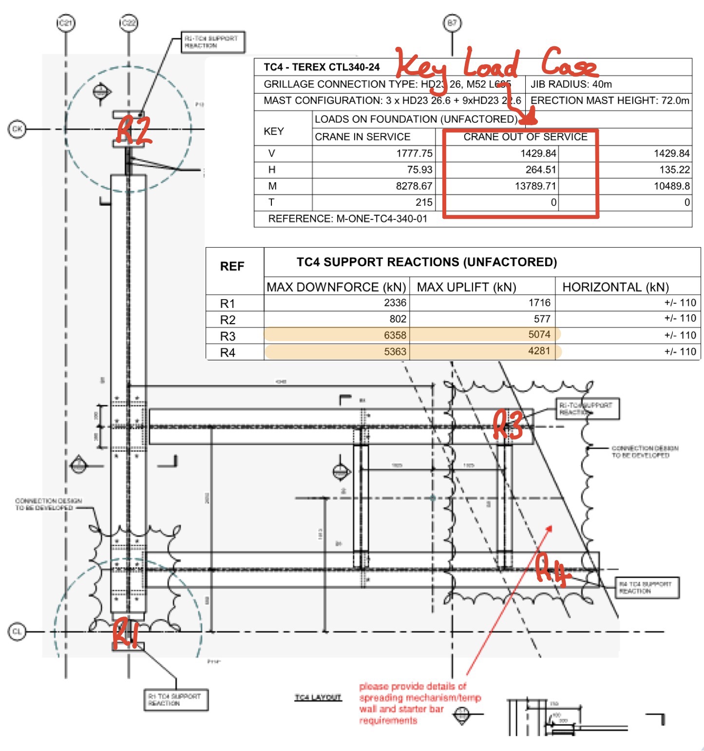 The plunge columns and piles have lots of spare capacity, provided the detail of the connection doesn’t create a load at an eccentricity and hence large moment. The D Wall however has very little spare capacity, I suspect this is because the designer has been very conservative due to the presence of a scour feature. Anyway when I went to the designer and said MPX want to put almost 13MN in two point loads on the D Wall he laughed in my face and said it’s not possible….. Que lots of head scratching by most of the MPX Engineers, calls to various people to move cranes, reduce sizes and extra piles flying in everywhere.
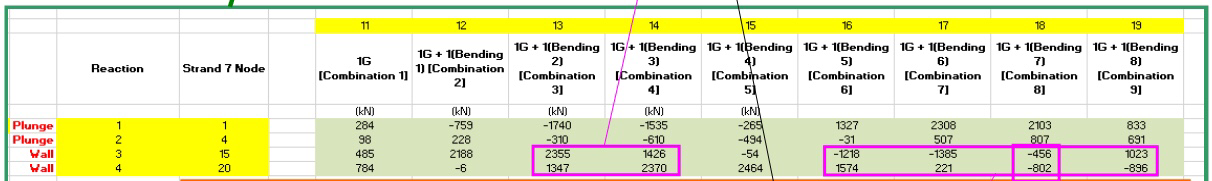
Anyway after a day of flapping and the drafting of a few concept ideas, a small structural firm called BG and E where emailed the concepts to have a look at. The Senior Engineer referred to the guy as an absolute ‘gun’, I assume he means he is your top third engineer. We went over for a coffee and a discussion, the first thing he said was “look at your load case, from the load envelope, Carey’s have provided the max and min for all reactions”. And here the penny dropped, its impossible to have max reaction on the D Wall at the same time, instead of text I have illustrated this below.
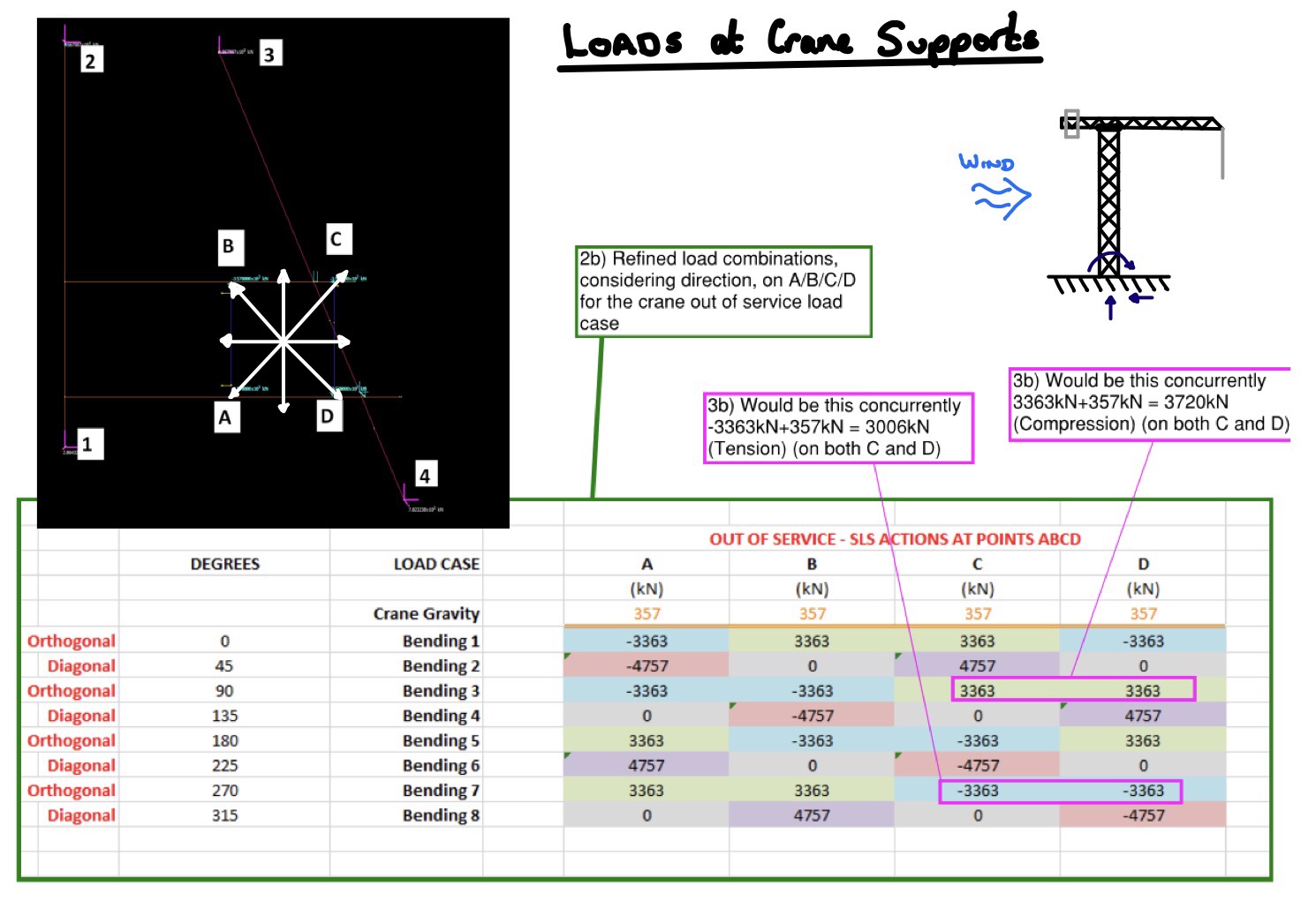
By considering the load envolpe properly the loads on the D Wall have dropped by 60% (combination 3 and 4 below), it will still be tight with the vertical capacity but potentially workable. I suppose in the long winded blog I am trying to say, always interagete loads given to you by another engineer before you plow on and use them, it saves embarrassing moments.
Ground Water and Retaining Wall
This is one for those of you with a keen eye for geotechnics I think.
I am currently looking at getting all the ducks in order and the sequence of the bulk dig on One Nine Elms. Prior to the excavation, a ground water pumping test will check that the basement box is water tight (more likely reduce the risk it leaks like a sieve). This has raised a slight contractural issue which has been missed in the scope of works and allowances the sub contractor has agreed.
The design of the D Wall assumes the ground water level at the level of the soil on the passive side throughout the excavation. However the pumping test contractor has not allowed for recharging the box after the test and the substructure contractor have specifically stated their rates for excavation assume the ground water level is below formation.
During a planning meeting I was quizzed fairly robustly, below I have summed up my response. Are my comments sensible or have I been an idiot?
1. Why would the sub contractor specify the GW level in their rates? If the GW level is at the surface, the excavated soil will be wet. Dry material will need to be imported and mixed with the wet before it can be transported and accepted at the tip, therefore resulting in cost. I also suspect bulking factor is dependant material and water content.
2. Would a lower GW effect the working surface? Yes it would improve it, effective stress goes up which is directly proportional the the shear strength of the soil.
3. Why would the wall be design like that, it’s not how it is constructed? It’s the worst case, the designer may have been unsure of the methodology so will have taken worst case GW and therefore higher pore pressure.
4. What would happen to the D Wall if the GW level was below formation during the dig? Errmmm….. it would effect the wall stability. See scribbles below, in short passive pressure would increase, therefore stability would be better.
 In terms of the strength, the SF & BM capacity of the wall won’t change as the strength of the steel and concrete is unchanged but the loads exerted on the wall will. I suspect the position of the max BM will change but be lower in value. Running it through software would have quickly told me this but there was none to hand and I didn’t fancy getting my pencil out, plus I would need to check at the various excavation stages. So my answer was weak in this regard.
The wall carries a vertical load, this can essentially be modelled at a pile with some of the shaft resistance gone i.e. where it is excavated. The wall will experience the max vertical load in the long term therefore it would be safe to say the construction methodology will not effect the vertical capacity.
Multiplex being a management contractor the would never rely on my advice, even if I put numbers behind it. In the end the design contractor will be paid to alter the GW level in their software and give the thumbs up. A 10 min job charge at a day or two fees.
One Nine Elms – How not to design a structure
So, hello everybody. I hope everyone is settling in well and the Australia lot are not too sunburnt. In order to not bore everyone by just regurgitating AER 1, I intend to give you a brief overview of my site and then discuss the main issue with the project.
HEALTH WARNING – it’s a long one, sorry.
One Nine Elms – Multiplex
I am currently a site engineer for Multiplex on the One Nine Elms project. Multiplex have been brought in by Wanda (the client) after a number of contractors had walked away, being unable to agree on price and the project was showing little progress being almost a year behind schedule. The current contractual arrangements are slightly confusing but in essence everyone is currently under contract directly to Wanda. Second London Wall (Employers Agent) are the clients advisors and Multiplex under a Construction Management contract, but with not direct control over the sub contractors. All this makes for a confusing and rather inefficient site however, Multiplex will be moving to a Design and Build contact in June with the client becoming Second London Wall. I suspect this will be a future blog or TMR once it becomes a little clearer.
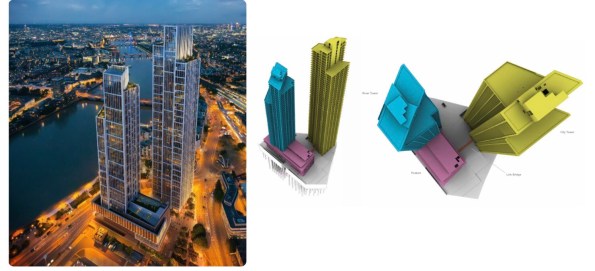
Fig. 1 Architects Impression (Left) and Superstructure 3D (Right) – notice the lack of St George Wharf completed in 2014
The site is the redevelopment of the Market towers, two 23 storey RC towers completed in 1975 and demolished by McGees in April 2015. Piling and groundworks began on site during the demolition and is not likely to be complete until the early 2018 which I will elaborate on below.
Superstructure
The superstructure consists of two high rise buildings referred to as the City Tower (yellow) and the River Tower (blue), the towers are linked at the first floor with a link bridge via a podium (purple). The City Tower is 56 storeys assigned for residential occupation, with the River Tower being 42 storeys with the upper levels being for residential occupation and the lower levels assigned as a hotel along with the podium. The structural concept for both towers is typically post tensioned reinforced concrete solid slabs supported by composite concrete encased steel columns and a centrally located reinforced concrete core. The reinforced concrete core along with its buttresses provide the lateral stability to the building, floor plates act as diaphrams restraining columns and transfer lateral loads to the core.
Substructure
There are two basement levels across the whole site with a third level between the two towers. A 1750mm combined sewer runs through the middle of the site which splits the substructure in two. Groundwater cut off is achieved by two 800mm diaphragm walls boxes either side of the sewer which have a toe depth in the London Clay. The foundations supporting the Superstructure consist of 256 compression and tension bored piles acting in conjunction with the raft at B2 level. These piles vary in diameter ranging between 1800mm and 900mm with the toe in the Thanet Sands. Due to the proposed construction sequence some of the piles contain plunge columns.
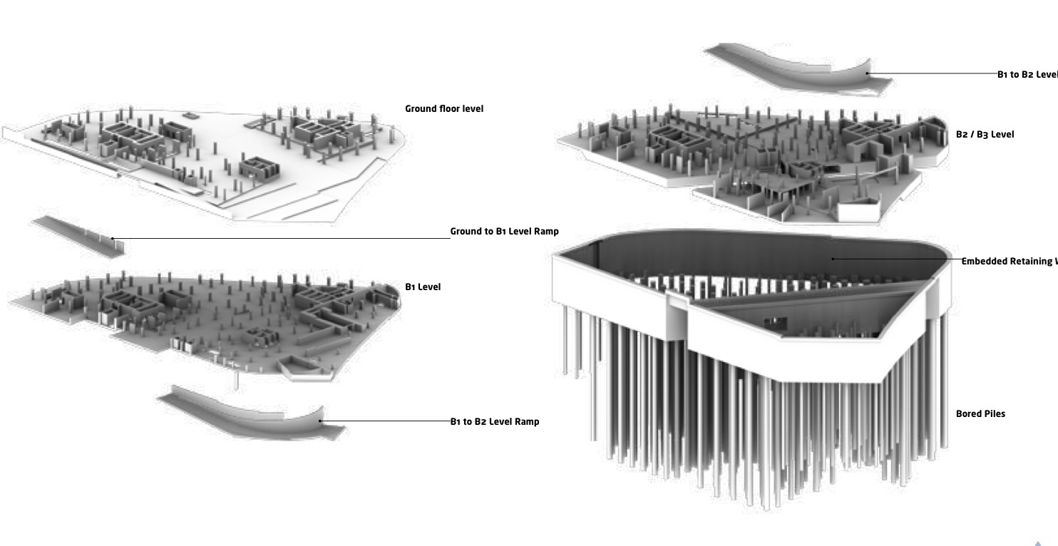
Fig 2 Diagram of substructure
Ground Conditions
The ground below the site is typical of London and consists of Made Ground (depths between 1.1m – 4.90m), Alluvium (depths between 4.5m – 9.5m), Kempton Park Gravel (depths between 7.5m – 23.0m), London Clay (depths between 22.0m – 31.5m), Lambeth Group (depths between 10.5m – 16.2m), Thanet Sand (depth between 9.2m and 13.0m) above the Newhaven Chalk Formation. Groundwater is between 3.7m and 6.4m deep and is known to fluctuate, with the level of the Thames. Fig 3 below shows the Lithology along the route of the sewer, there is a scour Pingo feature in the East of the site and it can be clearly seen on the right below.
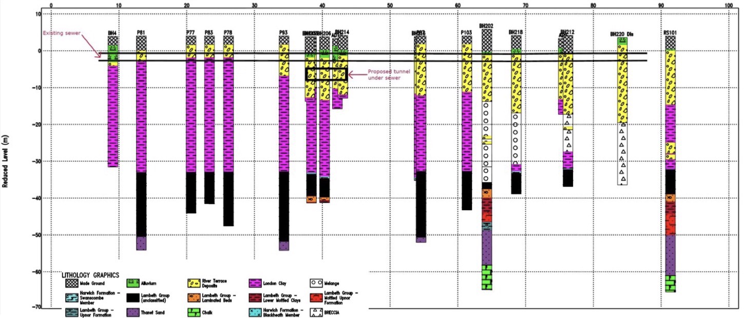
Fig 3. Lithology along the length of the sewer
Construction Sequence
The original squence and design was for top down whilst constructing the two tower cores on a number of plunge columns simultaneously, in theory reducing the project duration. However due to issues with the sewer which I will outline below the sequence has gone to pot and now looks like bottom up around the River Tower and top down around the City Tower.
Sewer Issue
As mentioned above, the site sits directly over an existing Victorian masonry combined sewer. The Market Tower (old building) basement structure spanned over the sewer and was supported on piles either side with a 1.3m to 1.5m exclusion. Where superstructure columns landed within the exclusion zone a 2m deep slab transferred the load to piles either side. The same solution has been proposed for the new building – First error!
The option to construct a new sewer around the perimeter of the site was tabled at a cost of around £2 million, this was rejected by the CEO of Wanda. The reason cannot have been for cost. The 150m of extra diaphragm wall, two 2m deep steel transfer beams, fabricated out of 200mm thick plate which take down a main load path over the sewer and the 1000 tonne crane to lift them in will cost significantly more. Mental!
Having made the decision not to construct a new sewer, the next worst possible decision would be to let the achitects put the taller of the two towers where the scour feature is. Hence requiring a greater number of larger piles to carry the larger loads in more difficult ground, which raises issues of conflicting with existing piles….. You guessed it. The core of the 56 Storey City Tower is smack bang over the sewer and in the worst ground. Not only this but due to load exclusion zone the two huge transfer beams mentioned above are now required. Mental 2!
So you would think with everything mentioned above, a detailed internal monitoring system of the sewer would be wise to compare displacements to expected values….. Nope. Wanda decided it didn’t want to waste money installing a detailed monitoring system during the demolition (against the advice of pretty much everyone involved in the project), instead opting for an Invar rod and tube system on the crown of the sewer. These are cheap but have numerous disadvantages, such as not being very accurate being suceptible to temperature change and being surface laid are easily tracked over and disturbed by plant.
Analysis was conducted to estimate the sewer movement during demolition (heave due to a reduction in effective stress in the clay) and settlement during the construction of the D Wall and permanent structure. This analysis predicted vertical sewer deflections of +27mm during demolition, +63mm during excavation and on completion of the superstructure of +28mm (que a JM rant on accuracies in geotechnics). An interesting point here is that the new structure makes a better job of spreading the load across the footprint of the site, hence the heave remember JMs voids ratio v effective stress.
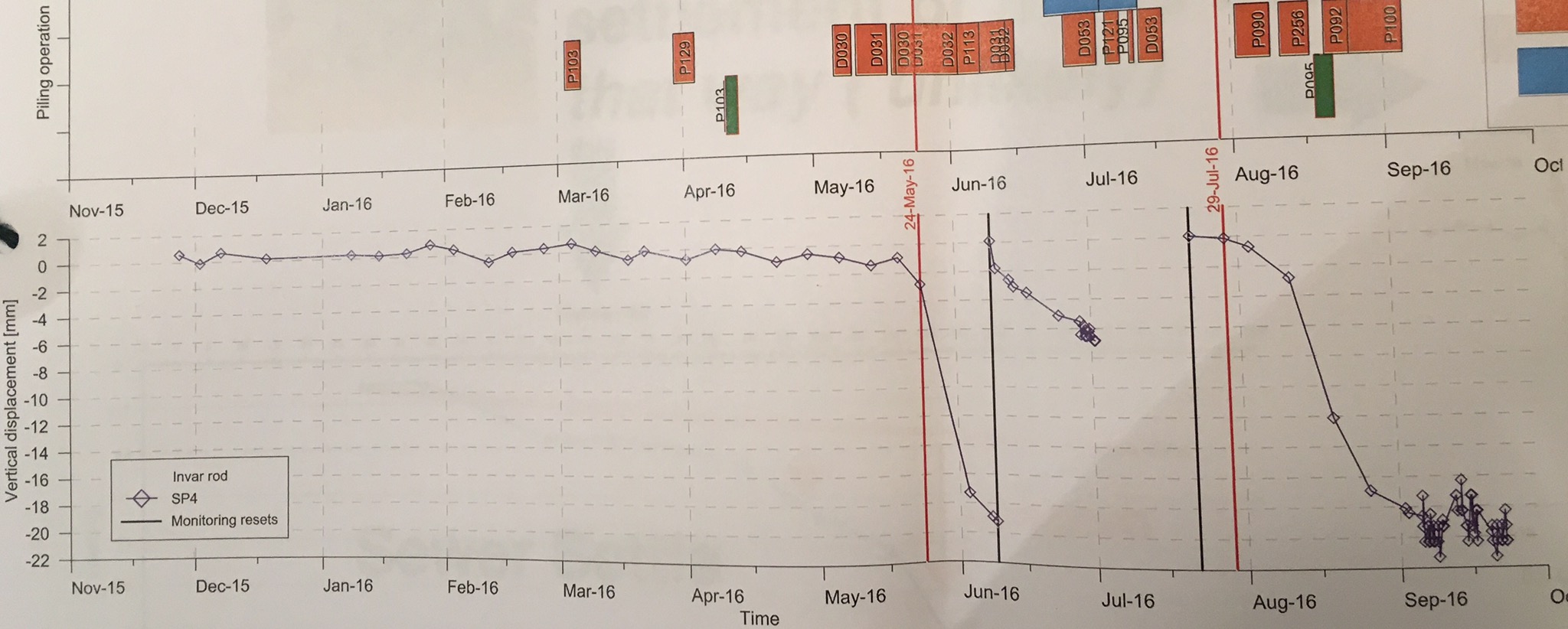
Fig 4 weekly Invar Rod monitoring results overlaid with activity, piling (green), Coring (orange)
As can be seen in Fig 4 above, the coring of existing piles for construction of the D wall seems to suggest about 50mm of settlement, combined with 200mm of settlement known to have occurred before 2013. This puts the sewer way beyond the allowable strain stated by Thames Water (TW). The large jumps and the rod resets (black lines), raise the question of the reliability of the results but if this is all you have then it has to be trusted.
As a result of this settlement TW have imposed a 7.5m load exclusion zone either side of the sewer, until its integrity can be guaranteed . This effectively makes the completion of the piling impossible and blows the programme to bits. The current solution is to line the sewer with a steel liner, this maybe jacked down the sewer or lifted into place by cutting out the crown. These are subject to TW approval of the method. This work will take 30 – 40 weeks which is a direct delay to the project, as the effected areas are on the critical path and at an unknown cost (this will be a subject of a future blog). On top of this the D wall and key piles for transfer beams can not be done until after the sewer remediation. The clamshell rig leaves site for another job next weekend, leaving an incomplete GW cut off and a fairly large bentonite farm in the only area where work can continue. This is a pretty big issue, these rigs normally require a big lead time, booking for 9 months or more and have a significant establishment cost. Due to the depth required and then associate problems on achieving interlock due to tolerances, a secant wall solution may not be possible. The resultant of this is Wanda considering purchasing their own clamshell rig at a cost of £1.2million and MPX under considerable pressure to demonstrate to the client that are worth there margins.
Sorry for the long one, I’ve probably glossed over some vital information so fire away.
