Archive
CCB – Ft LEE Training Facility
The ‘museum’ is still behind schedule. 95% submission is due mid – late march, a 3 month delay on the original. A rendering of the building is below, with my portion of responsibility shaded.
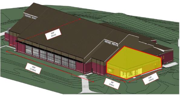
Ft Lee Training Facility
The larger space is largely progressed however the shaded portion, which is structurally separate, had not been looked at, other than producing a column grid and an interior plan. The promoter intends the space to be open plan admin and teaching space. Therefore a rigid frame layout is required instead of braced. This is comprised of lateral and gravity beams and columns, (with the latter being pinned at the ends, hence not transferring moment). I designed the frame keeping the lateral frames symmetrical as much as possible to reduce torsional effects induced by any wind or seismic loading. If there is not enough rigidity in the structure after running the seismic calculations I have enough ‘spare’ gravity columns which I can make into lateral columns to stiffen up the frame and retain some symmetry.

Structural Frame Design
The loading of the structure has been affected by the Protective Design Center (Sic) (PDC) who have said that the cold formed steel truss system proposed for the roof doesn’t meet blast requirements. This is strange because stud walls and metal decks, which also consist of cold formed steel, are adequate systems. To me this means that either they haven’t been able to test the particular roof truss system in question, or there is an issue with the truss connections. The roof system is ‘designed by others’ so options were to either specify a requirement for hot rolled angles to form the roof truss or provide a second roof. The first option would greatly increase the weight of the roof and affect seismic design as well as costs whilst the second (selected) requires joists and decking. That means that the load paths need to be considered and modelled appropriately. Instead of having the ‘high roof’ which will transfer the wind and snow loads into the frame, sitting across the joists it will sit directly onto the main frame. Modelling roof loading across the flat roof decking would incorrectly increase the joist size and would increase the costs unnecessarily. I will therefore model the ‘high roof’ loading as line loads running across the beam lines as shown below.
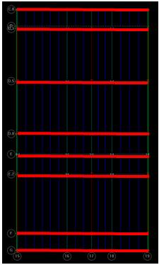
High Roof Loading Model
I will input the permanent and variable loads for the roof based on the relevant standards (in the same way as we get our values form the ECs) but I will also need to manually calculate and input the snow drift loads. These, along with the seismic loads have not been calculated for my portion of the building so I am grabbing as many design examples, codes and text books as I can, to handrail. The computer will automatically model the wind and seismic loading which I can cross reference with hand calcs.
Environmentally the site as a whole is legally required to maintain similar conditions to the pre-construction water run off conditions, in line with the Energy Independence and Security Act 07 (EISA 07). This ‘low impact development’ (LID) approach is managed by the civils (site development) department who will design in methods to ensure the targets are met. These targets will be set by the initial site assessment which will look at things such as hazmat risks (POL), asbestos water quality and quantity of run off.
The promoter will budget the costs of the designed measures (swales, pervious parking areas, filter strips, and vegetated buffers etc) which are required to maintain the site at or close to its pre-construction state. The estimated costs are entered as a separate line item on the form that is required to request project funds from congress and are based on 2% of the overall ‘supporting facilities’ cost. This policy is intended to ensure that all government projects have adequate funds available to cover any LID requirements. ‘Supporting facilities’ are anything that isn’t the constructed asset itself and includes such things as the electric, gas and sewer service costs, pavements, storm drains, ATFP and any other site improvement / demo costs. For this project the ‘supporting facilities costs are estimated to be $5.5 million, therefore implementing the LID measures has $110,000 budgeted. This will presumably form one of the constraints on the design. To me the figure feels low considering some of the effort that is required to treat water before it is discharged from site in line with EISA 07, however this line item will be added to all the others for the project and a 5% contingency added to it.
Building 8607 Renovation, Ft Meade. The Design Build RFP (aka ITT) sections are produced by the different departments in the Engineering Branch. I helped the costing effort by producing a rough schedule of quantities expected in the ATFP upgrades. I based this on drawings which were used in the upgrade of a similar project which used the alternate path method of hanging floors using tension rods in the event of a column removal.


With the odd exception most values required by the estimating department were in tonnes, so fixtures and fittings (bolts etc) had to be converted from individual units. Other bits of work, for example welding or demolition of walls, was required in linear or square feet. I was a bit stumped by how I should tackle the installation of the lift but was advised that a line saying ‘1 x lift’ was sufficient! Whilst I was happy enough with that it occurred to me that it would probably be a bit of a waste of time for me to do that because there are people who are much better placed to do it. My value came in understanding the structural components of the ATFP system and being able to dig into the weeds of that. The selected ‘preferred’ ATFP method has been based on the fact that it has been done before, and that is what has dictated the government estimate. However, the contractor may well decide to completely re-build the concrete framing and install a tie force method of ATFP while he’s at it. This could potentially mean that the government estimate is a long way off the contractor estimate which, if realised, will introduce a bit of risk into the tender process because it will increase the complexity, hence increase the duration, of the negotiation process. Having said that we had to start somewhere and using precedent seems as good a place as any in this instance.
Access Control Point, Ft Meade – This project is now due to start in July 16.
CCB – MPD at the Pentagon
Me and Henry got swept up last week in the Baltimore Military Professional Development visit, part of which was to the Pentagon to see a failed project. This portion only lasted a short while so I don’t know all the the ins and outs, but it was interesting none the less and raised some interesting points.
The project itself is to upgrade a goods and service entry point to the Pentagon, and is one of the final upgrades required for the whole site. It’s a job worth a relatively small figure but is fairly high on the Pentagon list of priorities. It was procured on a traditional contract and awarded to what is called an 8A contractor. That is, it was awarded to a smaller ‘disadvantaged’ company in line with the government social sustainability responsibilities. To qualify as a smaller company doesn’t necessarily mean it’s a ‘pikey’ outfit with a white van for a head office, and the company that won the award employs c. 500 personnel. It must also have a history of successful contracts which it will have submitted as part of its tender. As mentioned the contract was terminated by the government for non performance. It seemed that the contractor felt that it couldn’t complete the awarded contract due to the amount of variations it was presented with when it arrived on site. Apparently some of the SI was incomplete and there were a number of underground utilities which were encountered unexpectedly. This seemed strange given that to a contractor variation typically means additional money? Especially on government contracts where I’ve been told that some of the larger principal contractors have a reputation of tendering for work with the aim of tying the government contracts in knots (driving a bus through) and making small fortunes. One theory I can think of is that in adhering to government requirements there are certain administrative obligations placed on contractors. If the contractor was not used to this, which implies a lack of rigour at the contractor selection board, then perhaps it was not especially well set up to comply. This could potentially mean that payments (or a percentage of them) for work were held back by the government. This would affect the contractor cashflow and may have had the opposite effect to that intended. (ie demotivated the contractor)
The contract duration was around 12 months, however in 12 months all that had been installed was some signage and fencing and 4 manholes with connecting runs. Certainly not the progress I’d expect from a competent contractor this hints at a level of ineptitude or lack of direction. At present the Pentagon is demanding of USACE a resolution, which USACE is currently administering. The bonds will be cashed in and go towards paying the contract sum lost for payment of work to date. This will draw a line under the old contractor’s responsibilities under contract which will probably be novated to another principal contractor. The whys and wherefores are probably more interesting the deeper you dig, however because the case is current the guide was very tight lipped. What struck me was the risk that the government takes on in discharging its social sustainability responsibility, particularly on a project at the Pentagon, and the seemingly missed opportunity by the ‘disadvantaged’ contractor which will now likely never win another government job in its future
CCB – Security is A Very Dirty Word
Doing a Guz “two-fer.”
I’ve been working, briefly, on another renovation. An old laboratory built in the 60’s which is now to have some very heavy server equipment put in it. I say briefly because I’ve been kicked off the project by the client, annoyingly.
The request was to assess whether or not the existing floor could facilitate the server equipment loading. A preferred loading arrangement was given, along with the loads of the individual server equipment. The existing floor is a composite slab, 16″ deep steel beams with a 4″ thick slab on top. The slab should be 5″ but destructive testing proves otherwise. The beams are 10″ o.c and span 30′. I calculated that the capacity of the system was around 240kip.ft [325kN.m] and that an increase in capacity would be required due to the loads imposed by the new equipment. I proposed (or at least I would have) a simple framing system which could either a) tie into the existing steel columns, above the existing floor level thereby effectively suspending the equipment above the slab, which wouldn’t see any of the additional load or b) sit on top of the slab tying in structurally – forming (for want of a better phrase) a concrete sandwich between two steel beams. Both have various pros and cons that I could think of, but what I was surprised about was the magnitude of the additional capacity provided by a steel plate which had been welded to the base of the existing composite beam arrangement. It was a lot! It was an accidental discovery made from messing around with simple hand calcs, and an error I made in missing out the base plate initially. Fortunately I recognised that things were off and I went back to check why, otherwise I might never have thought twice about the numbers. The plate itself is welded to the bottom of the existing steel beam and is .5″ (12mm) deep by 8″ (203mm). So not insignificant. The reason it increases the capacity so much though is because of the change it makes to the second moment of inertia (I) of the whole composite section. The original composite section minus the plate has I of c. 975inch^4. The composite section plus the plate has I of c.1985inc^4. When you apply this to the MIFY equation you can no doubt see the gain in moment capacity; The I has pretty much doubled for a very minor change in y. This could be a neat trick to remember if additional capacity is required but other methods of engineering (say replacing beams, or installing propping) are not viable.
Anyway, like I say I’ve been kicked off the project for being Australian. This was discovered when I called the client to ask for specifics about the server equipment; exact weights, how the loads are transmitted to the ground, sizes etc. Clearly alarmed as to why there was an “Alien” poking about he fobbed me off to somebody else, who wouldn’t pick up his phone and presumably called USACE. Turns out its a classified project. Shouldn’t be a problem thinks my line manager, who knew this. Well it is.
Alan. I’ve said it before, you are entering a foreign country. Brace yourself.
And also:
Since hearing that local Dunkin Do’nuts is closing me and Henry have been doing our bit to increase their take.
CCB – 8607 Renovation
Work has been distinctly ‘bitty’ so far with the proposed work on the Fort Lee Training facility still being just that. A proposal. This is mainly down to IT issues which have now been sorted, thanks to a bit of a whinge to my line manager. To fill the void I have been working on the other renovation project I mentioned in my last post.
ATFP / Progressive Collapse
The output required is the technical specification and tender documentation, which is being produced by a number of different USACE departments (electrical, mechanical, architectural, structural etc) with support from the costing department and PM section. The structure in question is being transformed from an old barrack block into office and administrative space. The main considerations for the structural section have been to do with the anti terrorist force protection and progressive collapse system. The ATFP considerations are required because the costs of the renovation are more than 50% of the total value of the building, which is one of several potential ‘triggers’ in the Unified Facilities Criteria (UFC) documentation. UFC is suite of standardised Department of Defense building codes applicable to all branches of the military. There is currently no progressive collapse or ATFP installed because the construction of the original structure pre-dates the current requirements. The ATFP requirements are classed as minimal, limited to such things as stand off and observation requirements. These are fairly cheap and easy to achieve and can be designed in early provided the designer is given enough real estate to play with. In this case this not a problem and as long as the car park is sufficiently far enough away and no trees get planted with branches lower than 5’ all should be ok. The progressive collapse requirements, triggered by the fact that the structure is three storeys and will be a ‘primary gathering area,’ are more onerous. The UFCs say that for this category of building either Tie Force measures or Alternative Path design is acceptable. This renovation is part of an ongoing programme and both methods have previously been used in similar buildings. The preference is to use a tie force method which will see a large steel beam placed in the roof of the building supporting hanging steel rods in tension at the column locations. These tie into each floor slab, supporting it in the event of column removal. When I say ‘preference’ I mean this is the USACE preference, not necessarily the client’s (the client doesn’t really care how the building is made compliant with the UFCs, just that it is). This is likely because its been used before and is simpler practically than a retrofit alternative path solution. To this end the UFC requirements have been quoted, but only examples of tie force have been provided. But why not just state outright that tie force is preferred? The technical spec seems somewhat to be leading the eventual tenders to arrive at a pre-determined conclusion but is still allowing some room for design innovation. One of the things required for the project, which will not form part of the invite to tender documents is a cost estimate. This allows USACE to get a feel for what the incoming tenders could / should be. I provided a list of quantities of materials I expect will be required for the ‘preferred’ progressive collapse system to the costing team who will build the cost estimate. USACE policy dictates that if incoming tenders are within 10% of the government estimate there is no requirement to go through a negotiation phase to consolidate the difference. So in leading the designers to use the same system then perhaps the cost estimates will be in the same region, potentially speeding up the tender process. Time is, from what I have seen so far, the predominant driving factor on most USACE projects. In allowing some discretion however some cost savings may be realised.
Existing Capacities
The client’s brief will contain a list of requirements to turn the accommodation building into the required administrative and office space. From looking in the UFC I anticipate that this will involve interpreting the requirements and allocating enough space for conference rooms, partitions, storage and general office space. All of these have minimum loading, much like you can find in EN1991. The designer will presumably be trying to find a combination of the above space to meet the client requirements whilst trying to do as little structurally as possible. To help both us and the designer understand how much, if any, work will be involved I’ve provided an annex to the documentation highlighting the existing capacities of the floors.
These are formed from cast in place concrete T sections; 5” beams supporting a 2.5” thick 26” on centre one way slab spanning 24’. The beams have 2 #5 rebar top and bottom (#5 being 5/8” dia.) and the slab has a mesh of undetermined diameter, therefore assumed not to exist. Destructive testing was carried out at numerous locations and most of the above has been confirmed, except mesh was only observed in a few locations. I calculate* that the existing system has a capacity in the region of 17 kip. ft [23kN.m] moment capacity (positive moment) and 16 kip.ft [21kN.m] negative moment capacity and about 4.5 kips [20kN] shear capacity. Using a computer system called Enercalc structural library (if anyones heard of that?) I applied various loading conditions and assess that the designer can do almost nothing without the requirement to increase the capacity of the existing structure. Why is this important, and what have I learned? Its important to know as a client how much you expect your requests to cost. Like taking your car to the garage, you’re much less likely to get ripped off if you know what the likely costs of replacing your brake pads will be. You can either research this yourself or get someone else to do the research, perhaps because you don’t know what a ‘brake pads’ is. In this case USACE is doing the research on behalf of the client so the government department requesting the work won’t get ripped off and can appropriate enough funds from senate to do the work. I learned that clients can be a nuisance. They have yet to identify an end user, but have a few in mind. One of these few has requirements for Sensitive Compartmentalised Information Facility space which sent the electrical and mechanical team into a tizzy. I learned that technical specs and tender documents can provide more than just a bus route for Steve if they are considered properly. They can also do more by saying less in a good way as much as a bad way. I also learned that youtube has lots of really boring videos.
In other news
The snow has gone and I paid $550 to Nissan to fix something on my car. I don’t know what it was called but the flashing light on my dashboard has stopped flashing.
* using a mixture of class notes, text books and a helpful youtube video.
CCB – Phase 3
I started to transition to phase three very shortly before Christmas leave. I factored in around 6 full days of sitting at the Baltimore City Crescent Building (CCB) split over a two week period to settle. This would allow me time to meet and greet; sort out a desk space, IT and scope out the work. Amazingly it only took around half a day to sort out IT and I had a desk space waiting for me, which I gather is at odds with Henry’s experience. For me transitioning 3-2 has been much easier than 1-2. I started full time at CCB on 4 Jan, however have retained my access cards to site so I can go and get ‘a cheeky shufty’ before departing the States.
The Structures team I am working in now sits in a different Division to the Construction Division where I was previously housed and is physically sited in the Baltimore District headquarters building in downtown Baltimore.
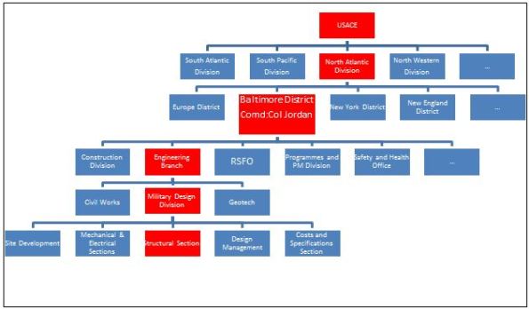
USACE Organisation
The figure above shows the organization, with red signifying where I sit. The Area Office where I was previously working was, like Henry’s, part of the Construction Division. Phase 3 sees me shift to the Military Design Division, which is a part of the Engineering Branch. Rather confusingly for a military organization the term ‘Division’ is no indicator of the position of the department in the hierarchy; Construction Division and Engineering Branch are equivalent departments, Construction Division and Military Design Division are not.
The Engineering Branch is responsible for the procurement, design and overall project management of federal and publicly funded projects. This is different to the Construction Division, who physically executes the works. Civil Works deals with levees and dams; Military Design deals with new construction and refurbishment projects; Geotech deals with geotechnical analysis, design of foundations and soil testing.
First tasks as part of the structures team include gathering an appreciation of the work available, described below, and becoming familiar with the US design codes and their application. Where opportunity and time permits I also hope to take on small portions of work from the geotechnical branch and site development (civils) team. This is fairly usual for the USACE placed students.
Below is the breakdown of what has been proposed so far.
Fort Lee Training Support Facility, Virginia. This is a $33m project which will be procured on a traditional contract with USACE conducting the design. It being undertaken by the Baltimore District, despite the site being situated geographically in the Virginia District. This is because Baltimore District has capacity whereas Virginia District does not.
The training facility requires a largely column free 120,000 sqft footprint in which various military artefacts and exhibits can be housed and moved around, depending on training requirements of the end user. As well as lecture theatres, toilets and workshops, associated with typical training facilities, there is also a requirement for an armoury, which must conform to its own set of construction standards. The training facility project could be defined as a museum, however because this would invoke more stringent, regulations and because it is not open to the public this is not the case. The requirements for humidity control and airflow are however being taken from museum standards in order to ensure the protection of some of the more delicate training aids and artefacts. The requirements for the movement of training aids, some weighing up to 90T also means that the typical reinforced concrete slab on grade (ground slab) has certain strength and ‘finished flatness’ requirements so will be designed more like a pavement, similar to runway design. It can be seen therefore that the design of the training facility allows for some freedom in the selection of which standards apply.
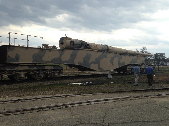
Example Training Aid
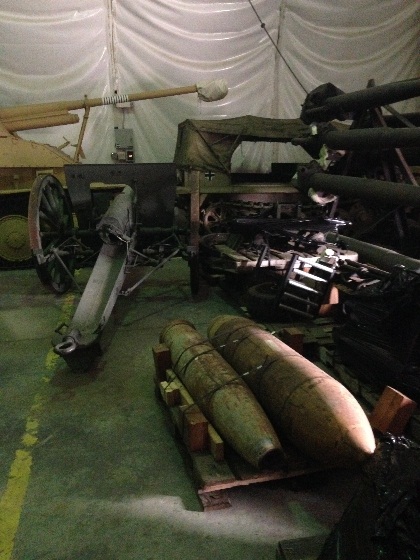
Example Training Aids
The project is at 65% review stage, however is recognised as being more like 30 – 40% complete. This is mainly due to issues with the completion of the Site Investigation (SI) and subsequent Geotechnical Design Report. This was sub-contracted out, however issues with the scope meant that the SI required completing twice as insufficient information was gathered first time around. A comprehensive GDR for the project is still forthcoming, however for the purposes of project progress assumptions have been made about the bearing capacity of the soil. This means that a large risk to the project lies in the ground conditions since design is being based on assumptions which have not been fully verified. This has the potential to increase the project costs to the client at the execution phase and highlights the importance of a sound scope for the SI in the first place.
The site itself is a forested marshy area, which has been largely created by surrounding projects, which have drained their sites into the proposed area. It slopes across the length of the project causing an 11’ elevation difference between one end of the training facility and the other. At around 30’ depth there is a thin highly compressible clay layer. This makes the project susceptible to long term continued settlement issues, in particular due to the large surcharge placed on the ground due to fill the fill required to level the site. The current design stipulates that shallow foundations should be adequate, which surprised me on hearing the outline ground conditions.
The requirement for open space means that the proposed steel construction will not be braced. Instead a steel portal frame design is chosen. Spans of up to 60’ mean that both standard and built up girders are insufficient and so a truss system has been chosen to try to maintain ‘a lighter appearance to the members.’ The sizes of the outer faces of the building mean that lateral wind loading and seismic loads are high. This means that the moment connections and details require careful consideration to ensure that lateral loads can suitably be transferred through the trusses into the columns and foundations.
My responsibilities will be to assist the lead structural engineer with verification and detailing requirements. I will also be involved with the shallow foundation design. The 95% design submission is due in June 16.
Building 8607 Renovation, Ft Meade. This is a design build project and so USACE is only required to produce the technical specifications and tender documentation on behalf of the client. Because there are Anti-Terrorism Force Protection considerations (ATFP) it is, however, likely that there will be some more focus paid to conceptual design. This may extend to some initial element sizing and direction as to which ATFP approach is suitable I have been told to get a software license for STAAD Pro to assist with a bit of modelling to test assumptions that go into the specification (so thanks NJP).
The project scope is to turn existing accommodation buildings into administrative space within the existing Ft Meade camp. The tender documentation is required to be complete by mid Jul 16. This is likely to be background work in addition to the main training facility project described previously.
Access Control Point, Ft Meade. This is a $20m project procured on a traditional contract with USACE conducting the design work. The requirement is for a fairly generic access control point to be installed at Ft Meade, consisting of several inspection lanes and indoor areas for security staff. The inspection lanes are simply steel hollow section columns with steel deck canopies spanning across the point of entry. The canopies won’t resist lateral forces and so essentially the steel columns will resist gravity and lateral forces as cantilevers. The indoor areas and inspection lanes also require to provide some element of protection for security staff and so will require design for impact and ATFP.
Other. As stated there may also be scope to grab some civils work from the Site Development team. They deal with horizontal construction such as pavement, storm water drainage etc and could be good for some additional sustainable development exposure as well as exposure to a broader range of engineering. This combined with the different structural projects which are at different stages of design should provide a fairly rounded design experience.
In Other News

Mike O’Callaghan–Pat Tillman Memorial
This…
and this.
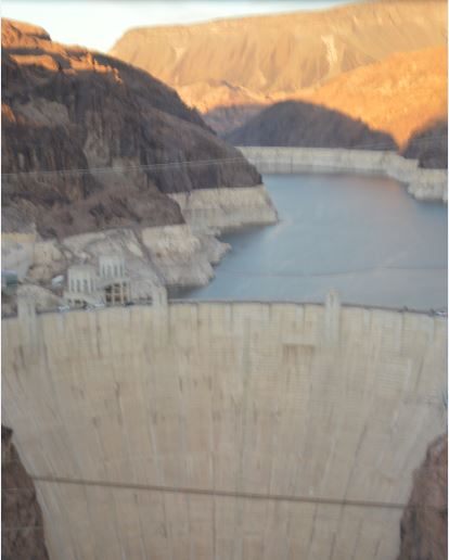
Hoover Dam
CRAC & Pipe
I recently handed back my Leadership in Energy and Environmental Design (LEED) responsibilities, which I’ve been covering for the last several months whilst the actual LEED Accredited Person (LEED AP) was on maternity leave. The timing coincided with the resolution of an issue which was high on the principal contractor’s ‘concerns’ list. It involved a Computer Room A/C (CRAC) unit and is another example of some poor contractual documentation which has led to confusion on this job. The issue has been exacerbated by the fact that the project is constrained quite heavily on what LEED points it can pursue, making those which it can particularly valuable. The issue started with an RFI submitted through the usual channels. It was labeled as ‘hot’ because it was holding up the delivery to site of the CRAC units.
As you can see from the contractor’s calculations below the Life Cycle Global Warming Potential (LCGWP) appears to be in excess of the LEED stipulated value of 100.
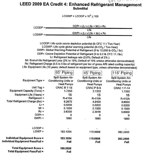
Contractors Evaluation of LCGWP
After a little digging I found out that this calculation was incorrect because it was based on the three units in confinement, when the actual calculation is meant to take the whole system into account. Although these parts of the system appear to be way out of the environmental requirements the system as a whole still passes. This fact made up a part of my eventual RFI response.
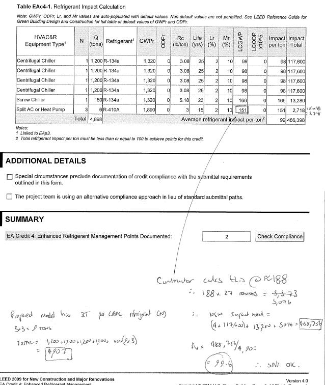
My calculation of LCGWP of whole system
The second part to this, and most importantly is the root cause of the problem. This was in the way that the requirements were communicated; there is conflicting information on the equipment schedule. As you can see below, the table calls for a DRCU-312 unit, but note 4 calls for the DRC-334 model.
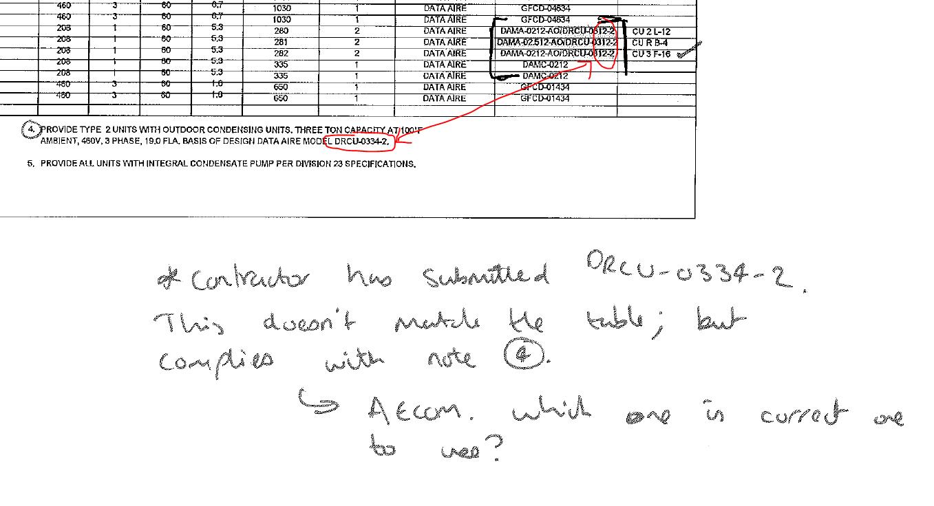
Conflicting information in contract documentation
Although it has been shown that the impact is minimal and the system as a whole still passes the issue has still caused delay in delivering the CRAC units to site. This has in turn delayed the overall system installation. Fortunately this work does not fall on the project program critical path and so impacts are minimized.
This is one example of many which has highlighted issues with the contract documentation. I imagine the designer will have done some design quality control (buildability, inter-discipline co-ordination etc) but they do seem to have missed quite a lot. I expected, on a large project, that there would be some discrepancies and bits of missing information but I have been surprised at how regular an occurrence it is here. Are any of you having similar issues or is it just this designer being slack?
For me, key take aways are with respect to quality control. This is not just a site practice, but starts at the very outset of a project. It is important to control the quality of the contract documentation also, and ensure that the drawings, schedule, specifications etc are all ‘synchronized.’ The impacts of not doing so can affect all three elements of the time/cost/quality triangle. As future PQEs I expect that a large element of this will fall to us to do.
A completely separate issue, but which loosely stems from the same root is a conflict between adjacent projects. Here a drainage run from one project is required to be installed in shared space. The conflict arises due to an electrical ductbank, which is hardened, and has been installed slightly out of alignment, and at a higher elevation than design due to various other site constraints. This means that it now sits pretty much exactly where the adjacent project’s drainage run is supposed to go.
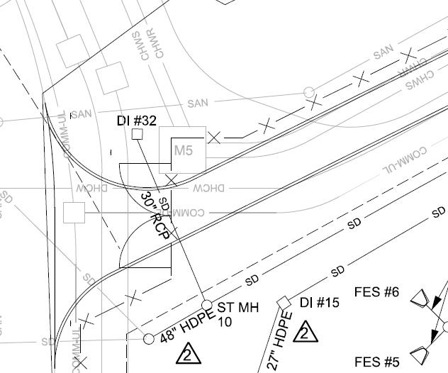
Original Design – Drainage run in question is DI32 – SD10 running under the road.
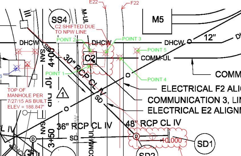
As built showing shift in ductbank centreline
Solutions I was able to proffer were move the drainage run run to the East of the ‘M5’ structure or change the inlet type. Both solutions would require re-design / confirmation by the designer because of the potential changes to the drainage areas, and requirements for confirming flow and velocities in the amended drainage runs. The first option was ruled out fairly quickly when I looked at the elevations of some of the other utilities in the area and realized that the pipe would have cut straight through some other utilities which had already been installed. Option two was therefore looked at more closely. The designed inlet was an overflow type, quite common here and usually seen in bio-retention ponds.
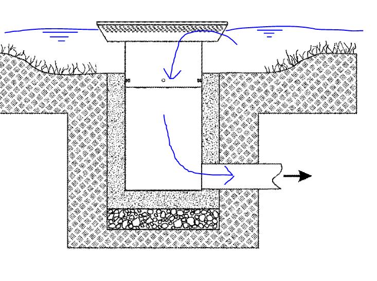
Typical inlet sketch
This inlet type meant that water would pond until it reached the inlet level, then enter the drainage by falling into the inlet chamber and on into the pipe where it is carried under the road (see original design above) and into the drainage system. It was the drop into the inlet chamber which was part of the problem here. By changing the inlet to a culvert instead the same function is achieved, minus the initial drop in elevation. Negating this drop meant that the drainage run could now pass over the ductbank, which it was previously conflicting with. See sketch below using, made using information from the as-builts and design drawings.
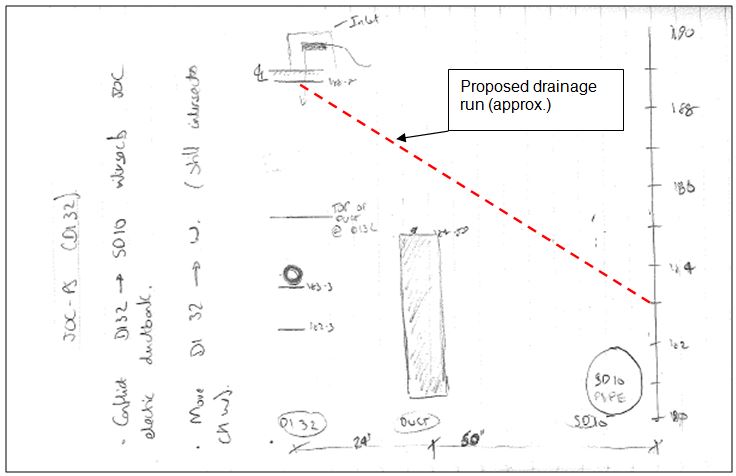
Sketches from notebook
I proposed to the designer that the inlet design was changed and calculated that a gradient of around 5.5% would maintain the original designed invert of the pipe at the SD10 (see picture above) This meant that the manhole structure which had already been delivered to site wouldn’t need to be changed. Any more than 8% would conflict again with the ductbank. Steep then!
The design came back from the designer yesterday:
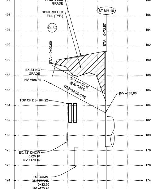
Approved design
Its hardly ground-breaking stuff, but it does throw up some pertinent issues. Firstly the obvious deconfliction of adjacent projects. This has been a near constant issue, and one which has caused some contractual variations. Clearly the best way is to do it early. In this instance it can be seen that information about the location of utilities were made clear to the adjacent project, however in squeezing in a drainage run between so many utilities the adjacent project has been burned by, I guess ‘unforeseen ground conditions.’ (ie the ductbank wasn’t where they were expecting it to be). Second the fact that the client on my project has the requirement to harden utilities. I gather that it is far from standard practice, but concrete wrapping ductbanks in areas of high utility/ services congestion adds to the complexity of installation. Predominantly this is because of the space required, but also it takes much longer and costs a lot more. I’ve been able to make a large saving (I blogged about it earlier) by questioning the requirement to harden some of the less critical utilities here. There is also the question of maintenance? In any case, in this instance the client would not have given latitude to remove the requirement for hardening, and so the conflict will always have arisen. There is however a minimum level of cover to be observed on ductbanks when they are close to the surface. Perhaps if this was applied to those at a deeper level, as a sort of ‘fudge factor / buffer zone’ then the designer might have been constrained at an earlier time in the project and might have arrived at the culvert solution in the first instance.
Changing Seasons
An interesting Chemical Anchor letter in the NCE, link below:
What is interesting about this is the warning which the author gives and the prevalence of these anchor systems on my site. In one case design starter bars were ‘RFI’d out’ of the design in preference for a drilled and epoxied system to be installed at a later time. The rationale being that leaving the starter bars out of the floor room my subsequent work, and was less of a safety issue.
Epoxied rebar to replace CMU starter bars
I had HILTI delivered training which supports the letter; there can be a huge loss of design strength in these systems if they are not installed properly and, by HILTI reckoning only 20% of anchors are properly installed. HOWEVER, these systems can be very effective. So what? If these are specified on your site, or indeed if you end up specifying them as a part of your design phase then just make sure that the tradesmen installing the systems have the correct qualifications and equipment otherwise, as the letter highlights, especially in safety critical applications you may ‘have dramas.’
Changing Seasons affecting Work
The cold weather is encroaching slowly but surely (a bit like my progress towards the finish line of a recent ten miler). This has highlighted a slight lapse in the PC’s QC process in-so-far as there is a cold weather plan for the placement of CMU at my central utility plant, but it is not being stuck to. On a recent cold snap the block had become too cold and the grout samples were not being taken by the specialised testing sub contractor at a representative time. Nor was there a QC rep on site to remediate the issue. As QA acting on behalf of the client I was required to step in; the simple fix being to stick the blocks in the sun for a while to heat gradually and use warm water in the cement mix to maintain the correct temperature (per the plan). I engaged with the QC manager to ensure that as the cold weather becomes more frequent there will be a QC rep on site at time of the key risk, in this case first thing in the morning when the very first blocks are being laid.
False Reporting
I conducted the latest pencil walk last week in conjunction with some of the other area representatives (M&E, architectural). There have been some discrepancies in the PC reporting, including the reporting of percentage completion of a scheduled activity which doesn’t tally with the expected remaining duration. It seems that it is easier to project the cost of an activity rather than its expected duration. At present activity percent complete is reported and agreed, and the remaining duration and accrued cost of the activity is calculated. For payment this is fine, because the payment estimates are fairly accurate but for remaining durations it is not working. This is leading to a false representation of the project completion, which is what the client, hence USACE is interested in. In some cases (my CMU for example) the original duration was estimated at 15 days, based on a 5 day calendar. It has been going on for almost 2 months now. It is around 65% complete, which means that the computer thinks it has around 5 days left to complete before the successor activity can proceed… In actual fact the successor activity can’t proceed for, in my opinion, another 15 days. This will eat into the activity float. Not a problem for my CMU, which has oodles of it, however if an activity with less, or no float has this issues then the critical path might be affected. The PC now has to walk through and agree actual remaining durations with USACE on future pencil walks to ensure the accuracy of reporting. This will help more accurately reflect the contract completion date. Below is an example of the issue – the overhead HVAC has an original duration of 40 days, is 25% complete yet has an anticipated actual remaining duration of 60 days.
Example from pencil walk
Stormy Weather
Quite an eclectic blog, due to the range of ‘stuff’ going on at the moment…
Safety
My Chiller plant is progressing well with CMU going up, albeit at a fairly modest rate, and MEP being hung. One of the over-arching requirements of the project engineers is to keep an eye on the safety aspects of the work. The CMU walls are braced as they are erected until they are tied in to the structure. This occurs when the top bond beam is in place and secured to the roof joists. As the walls get higher so do the braces. I hadn’t seen any braces being moved so I thought I would take the charts, which were discussed at the prep meeting, on my site walk and have a look. For some reason the braces hadn’t been moved, a fact which I highlighted through the principal contractors’ safety chain. They were fairly swift in rectifying the issue with minimal fuss. Below is a copy of the chart which is in the manufacturers product data, submitted as part of the prep meeting. I measured the brace run as 10’ but the wall had progressed to c. 28’ in height.
CMU bracing chart
Changes
I am drafting a Basic Change Document (BCD) for some concrete pedestals onto which a large piece of mechanical equipment will sit. The contract documents call for a wall of 12” width, which is what the PC has built. The mechanical equipment features in other areas of the programme, except in those projects the support pedestals are 18” wide…
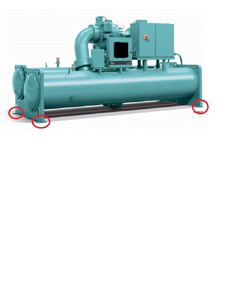
Not sure why theres so much white space…
The picture above shows the mechanical equipment with the anchorage points circled. These have ¾” anchor bolts drilled through them and epoxied into the concrete pedestal to a depth of 4’. An RFI was sent to the Designer of Record (DOR) who confirmed that there had been a design bust and sent a bulletin updating the contract drawings. Since the PC didn’t want to demo the pedestals the DOR also sent out an option to anchor the equipment to the thinner pedestals. This option required the mechanical manufacturer to add extra anchorage points to their equipment, along with some restrictions on anchorage distances. I didn’t think anything of it at this point; the PC was happy that they were no longer required to demo the pedestals and could engage with the manufacturer to arrange for the fabrication of additional anchor points and USACE was happy because the change was fairly minimal. I then sketched out the dimensions (below).
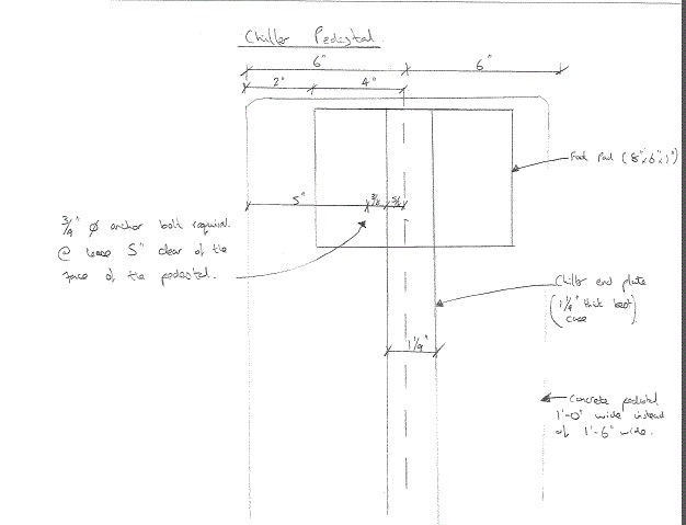
Now, it is easy at this point to berate the DOR however it should, in fairness, be noted that the mechanical equipment in question had not been firmly agreed by the promoter at this point and hence some of the dimensions were ‘a bit fuzzy.’ So. Plan A it is then; demolish the pedestals.
I will write the BCD which is essentially a Request for Proposal (RFP). It will go to the PC who will send us their proposal for how much they think the change of scope will cost. Independently we will produce a Government Estimate (IGE) which will be followed by negotiations to agree a ‘fair and reasonable’ price for the work. The contract will then be adjusted to incorporate the change and reflect the increased project cost. The last BCD I wrote produced a $200k debit, so I’m hoping to still be in the black after this change. Provisionally $28k has been set aside! Seems a lot but I’m doing the IGE shortly so we’ll see.
As Builts
Another area where I’ve been addressing issues is with regard to red line drawings and as builts. The focus was bought to this area due to a drainage run which was installed at the wrong elevation. When the adjacent project ‘found’ the drainage run with their plant, somewhat unexpectedly, we asked the PC for their red lines, which took about 3 days to get a hold of. This set alarm bells ringing – it became clear that, in some areas at least, they were not properly being maintained. I was tasked to write a letter and attach an agreed Memorandum of Understanding (MoU) relating to as builts, highlighting the contractual requirements for the PC to maintain 2 sets of red line drawings, hard copy, which should be inspected weekly and submitted monthly with the pay application. (Note: A letter is a contractual ‘lever’ USACE uses because a formal letter obliges the PC to respond with positive action or a letter of explanation)
I wanted to negate too much to-ing and fro-ing between USACE and the PC, so I approached the MoU in an open manner, inviting the PC to meet up and discuss the issue; the inability of the PC to access that one red line when requested led to a lot of background information. It transpired that a verbal agreement had been made between a USACE employee (who typically was responsible for checking the red line drawings) and the PC such that the requirement for hard copy red lines was ignored and all red lines were electronically kept up to date. Since each PC site engineer has a field iPad which can access the drawings on site this seems sensible, however the arrangement was not communicated to USACE. I have incorporated this into the new MoU to do just that. It was also negotiated that USACE receives the weekly update onto our shared drives (using an external hard drive to do a data dump). This includes hyperlinks to all RFIs, mods, changes, specs etc and is a huge improvement on what USACE currently has and will make it much simpler to keep tabs on how up to date the PC is keeping their red lines. This should prevent a recurrence of the incident which kicked off issue in the first place. I have been asked to give a presentation to the rest of the project delivery team highlighting what the PC is contractually required to do with regards to red line drawings and propose the mechanism to keep tabs on their compliance with the MoU.
RFIs
We’ve ran out! Because the job is a design bid build RFIs go back to the designer of record, something I’ve noted before causes a lot of frustration to the PC because they are accustomed to design-build jobs and have a fairly good design capability in house. Anyhow, there was a set number of RFIs negotiated into the contract price with the designer, with design busts, errors and omissions being answered for free. At last count there was just shy of 1000 RFIs since the start of the project (Apr 14) and there is no money on the contract to pay the designer to answer any more. We can’t stop the RFIs because assumptions made by the contractor mean he becomes liable which is a false transfer of the risk because he is, likely, not indemnified for design faults or errors. So, USACE ‘tech assist’ which is already a busy department is now being consulted on RFIs. This is less than ideal because 1, in my opinion, you are not well suited to answer design / clarification questions if you haven’t got the background of actually designing the thing in the first place; 2 USACE is in danger of picking up some of the risk it has already paid to transfer by having somebody else design the project and 3 because it takes ages!
In other news
This…

Erection Plans, Payments, and Visits
Following on from the cryptic erection plan for the steel truss roof a meeting was called; the contractor was livid that their plan had been E coded. The start of the meeting was uncomfortable to say the least, but when we got into the crux of the meeting, ie them talking us through their plan it was evident that there was confusion even between the sub-contractor and the principal contractor as to what was going on. In the end the USACE contingent didn’t have to say much.
Whilst I have no doubt that the very experienced sub contractor would have been able to build the truss, and would have done so safely, probably – if we hadn’t insisted on a properly thought out and communicated plan that was understood by all it would no doubt have been a lot more painful. Simple things like staging areas, order of material delivery to site and sequencing may have gone wrong, resulting in on site fixes to get the thing up. The new plan was submitted while I was away and is much better, essentially being an isometric contract drawing that is coloured in to indicate different stages of construction with notes.
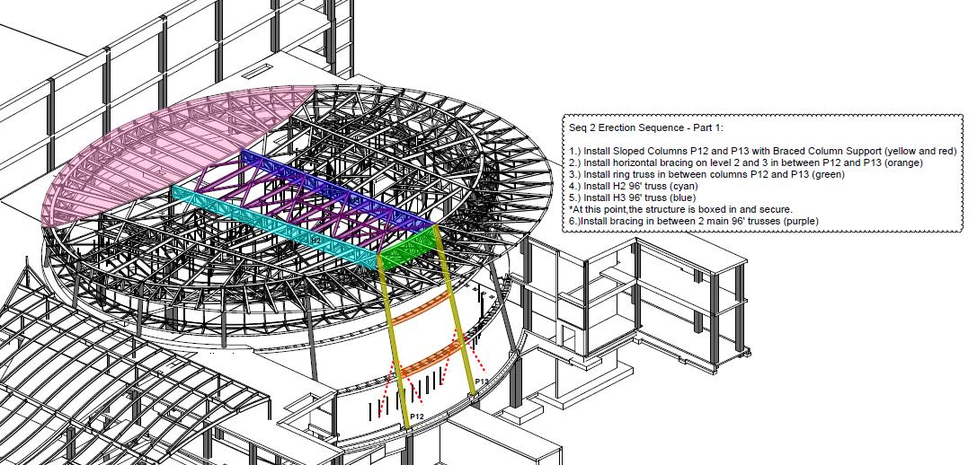
Example erection plan sketch
Example erection plan sketch
Although the document is still not paginated (chinned me right off) the step by step process is crystal clear through the use of drawings as included above.
Whilst I was away the CUP was pretty much completed (structurally) and is now a mass of Mechanical, electrical and Plumbing (MEP) hangars and Concrete Masonry Unit (CMU) walls. The CMU has a lot more to it than I thought and has been fairly interesting to see, but so far only minor deconfliction issues have arisen.
I’ve also got involved with the site ‘pencil walk’ to determine the percentages complete of on site activities and ultimately the payments to the PC. This process starts with the PC who submits their proposed percentages of works complete for the month to USACE. We then verify the percentages and negotiate discrepancies with the PC. I was surprised at how amicable this was, especially when I knocked back a few estimates. Some of the ‘agressive’ percentages are a floor in the system, which has a given data date by when percentages are required. This is not at the end of the month, and so field engineers are required in some instances to estimate how much work will be completed by the end of the month.
The agreed percentages are put into the cost loaded schedule and a narrative produced by the PC. This is agreed once and for all by the Contracting Officer who then agrees payment in the sum of whatever the monetary value of the percentages complete works out to be. The updated schedule is then published with the output being the ability to track the progress of the project in terms of project finances. By comparing the actual S curve to the baseline S curve you can get a feel for how the project has/is progressing and make assessments about manning levels and payment dates as well (payment requests are made 90 days before 85% of the funds are used up). The process is lengthy and requires considerable input to mitigate the risk of the PC over/under estimating his work but the utility of the output is in the ability to accurately report progress. The downside is that the most up to date conformed schedule is a month behind!
Another snippet that I gleaned is a floor in the proposal stage. At tender all the contractors submit a cost loaded schedule as part of the tender package. This is, for one, so that USACE can assess that the project can be built on time. The schedule is required by the contract to conform to a number of specification requirements, such as nil redundant logic, must be cost loaded, costs for procurement are to be included in the installation activity (to encourage performance), must be in the approved programme etc. This conformity, however, is not checked as part of the proposal grading when USACE is selecting a contractor to complete the works. This is interesting because the initial schedule is required by USACE 30 days after contract award as part of the pre-construction submittals. It is at this stage that scheduling issues are highlighted. An example of this issue is highlighted by one of the other projects on site which was recently awarded. Their initial schedule, and the one which they used to win the contract, has been rejected because it doesn’t conform to the specification and so they are having to resubmit as part of their pre-con submittals. To USACE its a bit of a non issue, because the contract has been awarded for a set price and duration, however it can put the PC on the back foot from the start. Fortunately though, the sooner you get behind the longer you have to make it up.
I’m also mid way through writing a Basic Change Document (BCD). This will alter the scope of the initial contract based on realities of site conditions. Initially the client wanted all underground power to be concreted in (in red concrete), including the electrical ducting to all the site lighting. Congestion of utilities across the whole site has led to a re-think of this requirement. The 3700 yards of schedule 40 piping initially specified has been up-scaled to schedule 80 piping but the requirement to concrete completely removed. This was after negotiation with the client who agreed based upon the likelihood of conflicts and the required time to place. The numbers are not yet confirmed yet but, across the whole site, there will likely be a $200,000 credit for the client and the relief of some un-needed headaches for the PC. I can’t help feel that if somebody had checked with the client at an earlier stage, that he actually meant ALL electric utilities should be concreted in, this might have been averted.
In other news: This.
The Defence Attache visits the site.
And this.
President Obama visits the site…
Which was interesting, not least because the entire job site was shut down for his arrival on half a days notice from the Client. Cue the e-mails from the PC requesting adjustments for delays. Fair one.
The Lost Thome
Apologies its been so long since I lost posted, you poor people! I found this post drafted and ready, from before I went on summer leave. I must have neglected to actually put it on the site in the rush to get out of the door.
The Chiller Plant is nearing completion (structurally) and the steel sub contractor building it is starting to prepare for its next large steel erection task on site. Construction of the Chiller plant has been somewhat of a rehearsal for the construction of a large steel truss roof, architecturally designed to be the crown jewel of not just the JOC project but also an icon of the campus. Colloquially known as the ‘Bridge of the Enterprise’ because of its elliptical shape, it will be more of a challenge than the chiller plant. So far it has been high on peoples agenda because of the proximity to an adjacent site which will make de-confliction of crane picks impossible. Cue the start of night work. This is an interesting issue in itself because the adjacent project is c. 1 year behind schedule and so the impossible deconfliction issue is not of our making. In the ‘real world’ I am sure that there would be much less accommodation made for the late contractor and numerous claims for LDs and delays etc. However USACE is required to manage the programme and so the success of both projects must be considered.
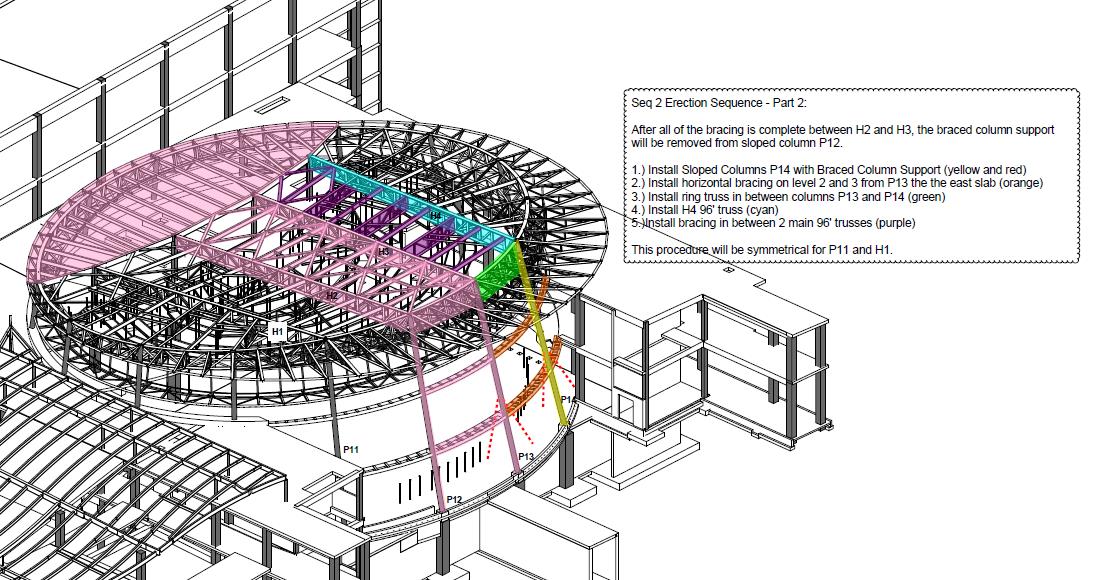
We also had to throw the erection plan back to the PC this week. I was part of the team reviewing it and gave general input about compliance to the USACE health and safety manual (EM-385) as well as being the ‘Structural Lead’ for the JOC, whose real Structural Lead was in Hospital with his wife who had broken her fingers playing American Football. The plan seemed OK on the face of it; containing all elements required by EM-385 (the USACE H&S document). These include details of site location, material deliveries, staging and storage, co-ordination with other construction, crane type and capacity, lifting methods, pick path, site preparation descriptions, stability of the erection, certifications …etc. The main bit of concern to me was the actual description of the steel erection activities. Fairly key then.
The subbie had done a brilliant job of communicating the first stages of the job on a simple on pager with different colours corresponding to different stages of the phase. It highlighted what the safe ‘walk away’ point was, was easy to read and clear (PSB)
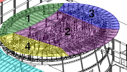
Colour Coded – showing sequences
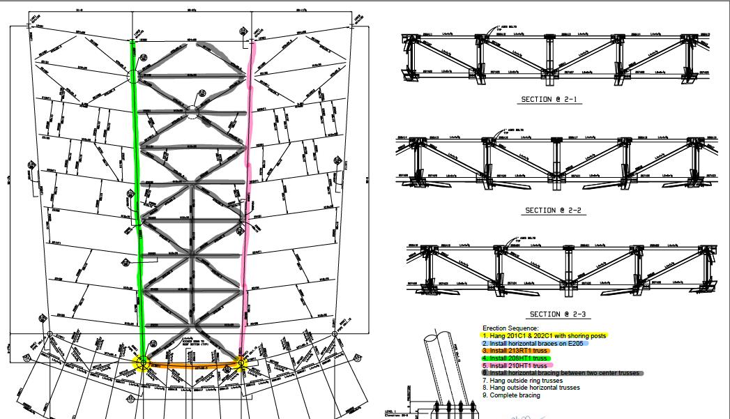
One of the sequences in detail
Unfortunately –
that’s where it stopped. I looked to the narrative for help, but it kept referencing other pages of the document, which was not paginated. It left me filling in the next stages based on assumptions and wooly assertions based on my knowledge of the project and a narrative that said ‘repeat steps 3 – 7’. To my mind totally inadequate. The erection plan itself should be a simple document that you could give to pretty much anybody who should then be able to look through and clearly identify at what stage the construction is at, what’s coming next and at what stage it is safe to terminate construction such that what’s already been built won’t fall down. If the subbie had simply done away with the narrative and continued with ten one-pagers I think the plan would have been much better.
So what’s the point of this bit of the post? 2 things: In the army we are gently encouraged to communicate on paper in set formats. This helps, and it’s a skill/requirement we perhaps take for granted. We can add a lot of value to a site / task / project through non-technical skills like these. But secondly the most complex of tasks can be communicated through the use of some simple, well thought out sketches. In this case, it would have been a lot better to have done so.
