Archive
Aquatar & Icon Tower
I thought it would be interesting to briefly post about a project I’m working on as it is a little different:
Aquatar is a brand new waterpark development on Etaifan Island in Doha, Qatar. The client is Katara Hospitality, a global developer of the Emir of Qatar. Atkins are delivering the concept design. The project involves 21 rides and attractions, a 75m iconic tower ride, themed bridges and various dry attractions. The waterpark site is located on Qetaifan Island, an area of recently reclaimed land on the coast north of Doha. This means the buildings will be subject to high thermal and wind loads, seismic actions and durability requirements of a marine environment.

I am responsible for the design of the Icon Tower which will be a braced steel frame with an internal reinforced concrete core. The tower will take the form of an offshore oil-rig type structure as seen in the picture above and in line with the theming of the waterpark. The height of the building will be around 75m with a base width of around 25m. The tower will have many water rides twisting around and through it meaning that saving space is essential to maximize the flumes passing through. These rides will be supported back to the primary structure by secondary steel bracketry (by others). The tower is located offshore on a separate reclaimed island (Icon Island). Lateral stability will be achieved by a combination of the core walls and action of the braced steel frame that will withstand all design horizontal loads from wind and seismic actions. Gravity loads consisting of self-weight of the structure, super imposed dead loads and live loads will be transferred via the floor plates to the braced steel structure and core, to the structure foundation.
![]()
Slide layout. Currently the shape and direction that the slides will go in is not defined. For the flume slides the average angle of a slope is 1:11. The actual path of the slides will be decided by the ride manufacture and will not come at this stage. What I am doing is considering average loads on the structure whilst waiting for a water slide manufacturer to provide me with loadings. The flumes will go around and also through the tower therefore I need to leave sufficient room between the tower bracing to allow this to happen.
Quick calc. Between floors 2 and 3 at 34m and 50m respectively, there are 5 flumes. Assuming each flume is 2m in diameter, and considering the most simple ride that goes in a circle around the circumference of the tower (they will be more complicated that this and this will cause even greater issues, however simply for this calc they go around the outside). The circumference at the bottom is roughly 78.5m. The height difference between 34m and 50m is 16m. At a 1:11 slope the length of flume needed to go from 34m to 18m is 176m. This means that the flume will go 2.24 times around the structure (176/78.5) within this 16m floor level difference. A single flume will take up 4.48m (2m high x 2.24 loops) of surface area over the structure of the 16m. 5 Flumes will therefore take up 22.4m of the 16m available. Tubes will therefore have to be hanging off the structure 2 wide in some locations, and will need to go through the structure multiple times in other locations. Space may be an issue.
This highlights some of the complexity we are working with and I’m sure will provide good blog material in the coming months. Now I’m off to dabble in some seismic loading.
Much Ado About Nothing?
Situation
When passing by the site offices I noticed the pulley system scaffolders had erected to speed their delivery of materials up a 12m viaduct wall, instead of using the stairs. I didn’t take a second look at first, as it looked like a routine and simple operation that they would carry out on a regular basis and “they must well know what they’re doing” it’s their specialist trade as scaffolders. However, I hadn’t previously checked their RAMS as this had been done by someone else so I was coming at this with a fresh pair of eyes.

Options
- Do nothing – it looks fine and is likely capable of lifting scaffold equipment. They must know what they’re doing.
- Question the scaffolders to get a confirmation that they are using the correct methods and that they know what they’re doing – I know they’ll tell me what I want to hear.
- Stop their works and do some checks. It just doesn’t look right.
I opted for the third one.
Issues
I used a method I recently learnt at a Multiplex 2 day quality training session I attended which included the use of fishbone diagrams for finding the root cause of nonconformities. Dubious as I was to their use, it provided another variation to a mind map. This gave me a number of routes to explore but I’m sure I will have missed elements out.

What appeared to be a simple situation can have a lot more to it as I found out:
- Work not covered in the RAMS. I checked their RAMS which had been filled out for the works to be undertaken on top of the viaduct but had not included delivery method and movements of stores. The RAMS had been checked but were not including the use of the pulley and therefore was not picked up. If it had included the lifting operation then the lifting operations coordinator would have been included in the checking of the RAMS. This means that the works shouldn’t have been carried out because they were not in accordance with the RAMS. The conformity and signing up to the use of RAMS is done by each individual at induction on site. This confirmed it was right to stop the works until the RAMS was amended and resubmitted for approval.
- Scaffold incorrectly constructed/not appropriate. What appeared to be a simple pulley mechanism was lacking moment carrying capacity. Looking at the setup I remembered portal frames and that if the load were to be transferred through 90 degrees, there would likely be a big bit of steel required at the haunch to deal with the induced moment. But surely they know what they’re doing and the scaffold connection is designed to carry the load? No – a diagonal member is required to carry the vertical load. This was not in place.
- Mechanism incorrectly fitted. After googling the pulley brand, it turned out they were using it the wrong way round and the brake wasn’t working – this made me think there was a lack of training somewhere in this mix of issues and that there could be other issues regarding the training.
- Knots. Individuals using knots to secure loads to rope must be level 1 trained. The previous item made me wonder whether this was the case and so I requested proof of their training – handily held on a CSCS card, copies of which are retained during the induction process on site. It turned out the individual was correctly qualified.
- Not valid document for pulley. The pulley itself was not provided with a test certificate. When asked to provide one there was a delay before a certificate was supplied. It came from the scaffolders’ office and is likely to have been put together following that request. However, there was no way of disproving this.

Learning Points
I consulted the HSE website, LOLER and the pulley’s operating and maintenance instructions (links supplied below), and have put together the following key points for the correct set up and use of a scaffold pulley wheel:
- The scaffold gallow bracket must be correctly erected (90 degrees with diagonal brace).
- The horizontal tube from which the pulley wheel is suspended should be fixed with right angled couplers to both the inner and outer standards.
- The Pulley wheel must have a fully functional brake (the braking action is compulsory and shall be automatic when the operating force ceases, whether the motion is lifting or lowering).
- Ropes must be the correct size to suit each type of pulley wheel (usually 18mm).
- If the rope has a hook attached for the purpose of lifting loads then it must be a safety hook, correctly spliced to the rope at point of manufacture.
- The pulley must be tested and examined before use and every 6 months thereafter (certification to this effect must be issued.)
- Weekly LOLER inspection of the wheel and rope must be undertaken by a competent person and the results recorded.
- Materials must only be attached to the rope by an appointed loader handler who is authorized, with evidence provided that they have received the necessary information, instruction and practical experience, particularly in the types of knots used to secure loads (minimum requirement must be COT course, H&S test and CISRS Trainee Part 1 Pass).
Conclusion
The most frequent causes of incidents regarding pulleys relate to the inadequate attachment of the load to the rope, the incorrect attachment of the wheel itself and a non-functioning brake. Specialist trades are assumed to know their methods of work and it is easy to think they have the definitive knowledge of a subject. However, whilst implementing their skills at the lowest level they may be using equipment they haven’t touched for some time or are unfamiliar with.
References:
CAP 609 General Information Booklet
Requirements for all “thorough examination” documents
Scaffold CIRSR training booklet and website “Construction Industry Scaffold Record Scheme”
Groundwater Disposal
Issue
Keltbray have commenced their bulk dig to B2 level in Zone A of The Stage, Shoreditch, experiencing silty gravel down to clay. Although not scenes from The Tempest, they are experiencing groundwater seepage with the following photo showing what was experienced over the course of one night (having left the excavation dry at the close of works yesterday, and yes I have raised the issue that if someone is working that close to deep water it should be barriered off and have rescue means in place).  The Keltbray RAMS had a plan to deal with groundwater by managing with sump pumps before installing a full dewatering system, discharging to Thames Water drainage via sediment tank on the suspended slab above. The issue here is that Keltbray have got a discharge permit in place but not a connection to the manhole for the water. This poses the issue of what to do with the water?
Source
The excavation sits on top of an approx. 15m thick layer of London clay and is surrounded by a secant pile wall installed by another piling contractor before Multiplex took over the site. The wall has a number of out of tolerance piles and gaps in it (as previously blogged by Fred Kiddie). There is also an adjacent Zone B currently at B1 level which has a contiguous wall separating the zones, therefore gaps between the piles. This means there is about a 5m head difference in the zones. My assessment is that this groundwater is flowing from Zone B to Zone A due to the newly established head difference. There is also the likelihood of groundwater flowing from outside the site, passing through some of the gaps in the secant wall into the excavation ie finding the shortest flow path. The site is in Hackney and is located in a former mainly industrial area with mixed uses for the land around. This means to me that there is a fairly high chance of some contamination in the groundwater. The final option for where this water is from is that the pilers have been experiencing more polymer being used in Zone B piles than has previously been experienced. This could mean that the new head difference from the excavation could be causing more flow from the polymer fluid out of the pile and into Zone A.
Options
Option one was to sump pump the water to a hole in the excavated material before mixing it with the spoil and removing using muck-away trucks.
 Issues with this option:
- It is a slow process.
- Some of the water flows back into the excavation.
- The muck-away trucks leave a trail of wet dirt on the road with very wet spoil being carried in the trucks – likely to cause complaints locally from the dirty roads even with one road sweeper employed full time.
- Each muck-away truck is tested for contaminants which would pick up any issues with contaminants in the groundwater.
Option two was to use the polymer pump and pump the groundwater into some of the polymer tanks and use it with the polymer for the ongoing piling. The polymer tanks can act as sedimentation tanks and ultimately conserves using mains water.


Issues with this option:
- Much faster at pumping the water from the excavation compared to a sump pump therefore making the excavation safer, quicker.
- The large amount of fines in the water cause the tanks to block up over time. However, these fines are contamination if not filtered out.
- The water needs treating to increase the pH before being mixed with the polymer.
- The water needs testing for contaminants as you could potentially be putting contaminated water down a pile and into a separate groundwater course much deeper down, causing wider contamination issues.
- There is a limited volume of the tanks for removing the groundwater as the piling ultimately reuses the water.
- The tanks don’t fully act as sedimentation tanks as their outlet valve is at the bottom therefore fines will pass through.
Summary
I have been discussing with the sustainability team here on the project who have cautiously approved the polymer tank method as it sort of allows for sedimentation of the water. The water isn’t currently being tested for contamination and the volume of the tanks has nearly been used up. I will be inspecting the water for any traces of polymer this afternoon to see if this is the source. If it is, then recycling the water through the polymer tanks isn’t such a bad option.
This issue only exists because a connection to the manhole has not been established yet. This is an item which is sitting with the local council and is an ongoing task to get approval.
The Stage
I have started my Phase 2 attachment with Brookfield Multiplex (MPX) as what seems to be a site engineer and construction manager on The Stage project in Shoreditch, London and I want to provide an overview of the project and site to allow future blogs to relate to it.
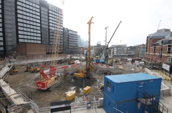
Location
As can be seen from the picture below, the project is within drinking distance of “The City”. It also sits next to two other MPX sites, Principal Place Residential and Principal Place Commercial. There are also numerous other projects going on within the immediate vicinity making for a very congested area of London. It also means that some of the MPX staff (mainly H&S and QS related) are cross-decking between the projects, splitting their time between the sites.

General
The development is a mixed use scheme comprising of a 37 storey residential tower (building 1 – prestressed concrete), a 14 storey office block (building 3 – steel frame), and a 9 storey commercial and retail block (building 2 – prestressed concrete). In addition to the three largest buildings there will also be a performing arts pavilion, heritage centre, sunken amphitheatre, popup retail units (to hide a dated masonry substation) and the conversion of former Victorian rail viaducts; and all to be done to a BREEAM excellent standard. There is also the preservation of the remains of Shakespeare’s Curtain Theatre which date back to 1577. These remains are of international significance and are being preserved as the focal centrepiece to the development, hence the name.


Contract
The project is currently in week 19 of 20 of a Pre-Contract Service Agreement (PCSA) and conducting early works using a JCT D&B contract between the Client and MPX. I will be spending some time with the contracts team to better understand how this works commercially. The background to this is that Gilliard Homes (the Client) originally started the project themselves and stopped it when things weren’t going to plan, then they appointed MPX as Principal Contractor. They wanted work to happen quickly which is why a final contract for the project hasn’t yet been established. What this means is that there are legacy issues on site caused by the work conducted by Galliard Homes. For example there are some incomplete secant wall capping beams in place of which Keltbray, the main contractor on site, cannot guarantee the structural integrity of and will have to demolish. There are also existing utilities which the Client had previously moved from outside of the hoarding, which now lie in the way of the secant pile wall design. This requires the UK Power Network (UKPN) and BT to be involved to move the utilities before the secant wall is constructed. All elements resulting from the work conducted prior to MPX result in a risk being carried by the Client.
Current state of site
The site is currently in week 11 of 50 of early works, incorporating secant pile walls and bearing piles before excavating about 18m to allow for a bottom up construction. There are 2 x 90T piling rigs on site with respective cranes, working on 1m thick piling mats. The ground is being excavated from +15m AOD to +11m AOD before props are installed to allow further excavation. Another important aspect of the project is the presence of the Museum of London Archaeology (MOLA), who are conducting archaeological digs on site. We were taught that archaeological finds are likely to cause a significant delay to a project. However, it is a key part of the brand of the development and MOLA’s digs are being facilitated by MPX throughout the project and time has been put into the program to allow for archaeological overruns. The only finds being preserved are those of the Curtain Theatre which dates back to 1577. This has been fully excavated and has since been covered using polystyrene, steel plates and some very expensive aggregate. This means that the area under which they lie can be trafficked and used for stores. The presence and exploitation of the archaeological site and its future use as a major tourist destination means that the development does not need to incorporate any “affordable housing”. There are also other archaeological digs being conducted on site but these will all be recoded and removed by MOLA.
Piling methods
Currently there are bearing piles and secant pile walls using guide walls being constructed. However, I noticed that contiguous piles were mentioned in the H&S plan. This will be a subject of another blog. In the meantime the piles here are CFA using polymer (polymer plant in the picture is hidden by the blue ISOs). You can hear the suction from the London clay when the auger is removed from the casing. I will also see the first of the plunge piles being constructed in the next few weeks. I will do a separate blog about the history of the soil in this area of London as it has some good historical background.
Key constraints
Hackney Council have a number of restrictions to the site, the first of which is the working hours. The site is limited to weekdays 0800 – 1800hrs and Saturdays 0800 – 1300hrs. This means that the piling has to be at a practical stage every day to finish at that time. Any over-size loads are only allowed to be delivered overnight or at the weekend. There are no actual sound limitations imposed on the site so the project has a self-imposed noise limit of 78dB, which is the average noise level measured from the city. A full pre-construction survey was conducted of the surrounding buildings and their movement is being monitored. Of interest is the tilt monitors installed on the listed pub at the western edge of site. I note that the monitor recorded 6mm of deflection at 2030hrs last night (everyone had left site by then), correlating with the pub opening times. It has also been noted that it deflects by similar amounts when the beer is delivered to its cellars. Every time a monitor, whether sound or tilt, is triggered it is automatically logged on Information Exchange (software) and a report is to be filled in. That, in conjunction with the pre-construction survey, are used to establish whether the site causes any damage to surrounding buildings.
Another building which forms part of the site boundary is a 1950s masonry UKPN substation which has already been damaged by the back of a bucket when a subcontractor broke from an agreed method statement, an issue of non-conformity which has all been resolved. It is being closely monitored for movement as it apparently supplies electricity to half of the city.
Issues
Live substations. There are currently 2 live substations on the site which require temporary substations for the duration of the project. The installation of the temporary substations and the removal and decommissioning of the old has already involved a lot of interaction between subcontractors and utilities agencies. It has been interesting to see how the interagency interaction is managed by the MPX team and has been the basis of me learning how MPX operate on the site.
Site accommodation. The site accommodation was inherited by the work done by the Client previously and is deemed inadequate for MPX. Its size and location is critical to the project’s progress and the responsibility for its implementation have been given to me. In the short term it needs a temporary expansion in its current location to cope with an increase in the female workforce, to coincide with MOLA increasing their numbers in June. In the medium term a 4 storey 40m x 12.5m modular temporary accommodation block will be built on a concrete slab still to be constructed on the southern edge of site. This will house approximately 1200 personnel and will be complete by November. Following this the existing site accommodation will be refurbished and expanded to facilitate the latter stages of the project when the personnel reduce and move out of the 4 storey block. I have now been given the responsibility of this site accommodation project and have mid tender scope if works meetings with two suppliers to discuss the options next week.
Office politics. The main construction manager has resigned (on my day 3) after being on the project 9 weeks. This means he only has to give 1 week notice and will be leaving next Wednesday. It would appear I am now mid handover/takeover with him, hence the site accommodation project switching to me. I have already seen there is a case of office politics, largely based on personalities. It will be interesting to see how this progresses and how it differs from what we are used to. It may stem from the project office being dislocated from the site office by a few streets; naturally I think this causes a bit of friction between the two.
Summary
This blog covers an overview of the project and an experience of my first week here. It provides a starting block to help orientate future posts about the project and gives a rough idea of what will be involved here at The Stage. Meanwhile I will come up with various ways of getting Shakespeare into future blogs.
