Archive
Farewell Multiplex
So my time with Multiplex is at an end. I have been on the Australia 108 project from Feb 16 and have had responsibility in various aspects of the project delivery, and nosed my way into the rest to maximise my learning opportunities. Site activities have included, large bored piles, CFA piles, basement excavations, retaining walls, ground anchors, jet grouting, pile caps and capping beams, pre-cast concrete, post tensioned concrete and lots of reinforced concrete in the form of the core, slabs and columns. I have also been responsible for the design coordination and delivery of the structural steel package, the car slider package as well as early construction methodology for the starburst.
At present state, the core has been poured to Level 6 with a hope to pour to Level 7 pre-Christmas, and the Level 2 slab has just been completed.


My time on A108 has been eventful and rewarding yet frustrating and challenging at the same time. It has been an invaluable opportunity with many positive experiences as well as some negative but I have learned something from each and I am a better engineer, leader and manager because of it. Phase 2 has presented significant opportunities to broaden my experience, test my technical knowledge, managerial and communication abilities.
Recommendations
To Phase 1 students I would recommend the following:
- Project selection – understand the project program and where the project will be within that program during your time on site. This will dictate what opportunities are available to you.
- Ownership – MPX struggled to understand the aim of my attachment and I have strongly had to drive my attachment to make certain I got the depth and breadth of experience I needed.
- Review – genuinely use the AERs and CPD record to review your journey to achieving your attributes. Where you have gaps, seek out other opportunities and experiences to ensure you get the most of your attachment.
- Preparation – trust that Phase 1 prepares you well, because it does.
How to erect a 390D tower crane
I thought i’d put up a photo montage of the erection of our second tower crane in case anyone had ever wondered how it was done – the crane is a 390D self climbing core crane with a 25t lifting capacity. I know it will especially interest all you E&M engineers out there 🙂
- 4 double towers and the slew ring erected first


2. Cab and machine deck crane on top of slew ring


3. A frame is craned into place


4. 45m boom erected in the loading bay completed with the compulsory Multiplex signage, electrical fittings and the monkey. Note the red and white markings in accordance with pan ops regulations (as we will be protruding into the ‘flight zone’ for a period of three months).


5. Cables fitted to secure the boom and prepare for lifting load
Spot the fearless bloke running around the boom!!
6. The final product awaiting commissioning…
All in all this effort took two 2 days to complete over a rather gloomy weekend.
P.S Tom’s addition to my blog following his comment:
One for the civils – concrete
We are having some issues with the supply of concrete meeting the specification (its under strength) and I am curious as to why and how this could have been managed better. I don’t think the contracts are robust enough to manage the risk of getting it wrong as we appear to be dealing with the aftermath of it all rather than our subcontractor. Tail wagging the dog scenario. The questions goes out there as to whether anyone else has had any major dramas with their concrete not meeting the required standard and have you had any issues with your supply chain? If so, what has been done about it?
Repeat answers from the whatsapp group greatly appreciated 🙂
Mechanical affecting the structural
I had a rather enlightening conversation a few weeks back and I thought it was time I finally got my act into gear to blog about it – and it is to do with lifts, or more specifically lift shafts.
Australia 108 will be 100 levels, 319m tall. This will present two significant issues with the serviceability of the lift shafts:
- Chimney stack effect. The temperature difference between the base of the building and the top of the building will be sufficient to induce an air flow up the lift shafts as the warm air at the bottom rises to the top (see Figure 1). Air is introduced at the base of the lift shaft by being sucked in though the lift doors, creating two undesired effects; firstly, the lift doors will likely jam and secondly, a loud whistling sound (often referred to as a howling). There are two fundamental options to deal with this problem. Option A) prevent air being sucked into the shaft (not feasible) or Option B) let the air do what it wants to do but provide an alternative inlet. Surprisingly Option B was the preferred option and we are looking at putting 2No 850 x 1000mm penetrations into the base of each lift shaft. Without providing additional outlets at the top of the shaft, we are not encouraging an increase in additional air flow to what naturally wants to occur.

Figure 1. Chimney stack effect
2. Piston effect. Of the 10 lifts, 9 are in banks of 3 and the goods lift is stand alone in its own lift shaft. The design speed of the goods lift is 5m/s (slower than the remainder) and is of sufficient speed to create a piston-type affect of driving air either up or down depending on the direction of the lift car. The displaced air moves around the car at a quicker speed sometimes twice that of the car (see Figure 2) creating undesirable vibration and noise. The effect is worse at the top, bottom and middle of the shaft (where the counter weights pass the car). To mitigate these issues, the cars will be made more aerodynamic and a 1000 x 2000mm penetration will be punched into the core walls at a low, middle and high level.

Figure 2. Piston effect
Prima Pearl is a 67 story building that that was completed in Jun 14 by the same management team as A108. The additional penetrations were not build into the core walls and have since had to be retro fitted to deal with the defects. Prima is 2/3 the height of A108.
Adding in air-relief penetrations seems like a good fix until you consider these penetrations were not taken into account on the initial design. In addition to these penetrations, there are also penetrations for the core crane, the hoist, two jump lifts, the jump form as well as embedded power conduit, water, waste water and sewer pipes that also, were not taken into account on the initial design. This is one core that is working extremely hard.
So what….think the design through to the finish throughout all stages of the life cycle and consult SME contractors to reduce the risk of missing critical elements of the design. This is not something I would have even thought to consider. The structural engineers are still struggling to make the core work in the serviceability state and every additional penetration makes this task that much harder.
Core wall modifications
Work has progressed significantly on site now. We have poured the basement slab, got the pre-cast walls to ground level installed, poured the internal core walls to basement level and completed the first pour of the ground floor slab. By the end of this month we should hopefully be well and truly out of the ground.


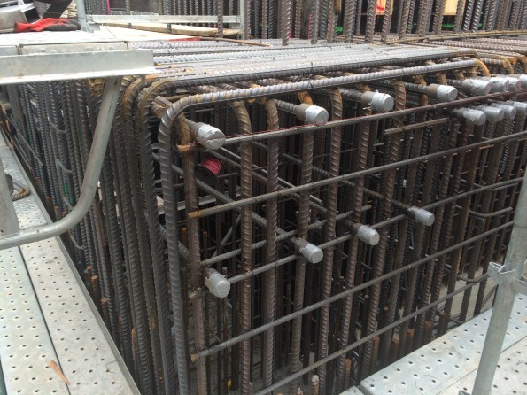
We have encountered quite a major issue on site during the last 24 hours with the external core walls. The wall was designed very close to its capacity with the strength being increased from 80MPa to 100MPa to make it work. The subcontractor responsible for the core capping beam has installed the starter bars for the walls 100-150mm out of position thereby reducing the effective depth of the wall by close to 10% as well as its capacity. This reduction in effective depth has tipped the wall over the edge and it no longer has the capacity to take the compression forces in the corner – the forces modelled are >150MN.
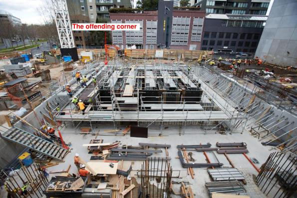
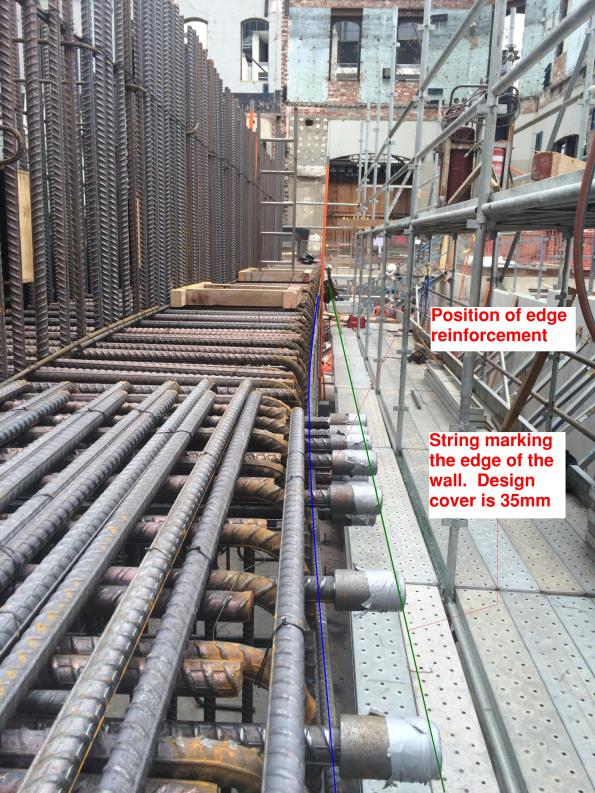
So what? The wall has been modelled and designed as a wall but due to the nature of the forces it must now be designed as a column which means compression ties. This will be fun when your wall currently looks like this….
Non destructive testing of concrete structures
How risky is it to estimate the value of compressive strength of concrete using a rebound hammer test (RHT)?
The concrete testing failed when testing the concrete cylinders for one of our pile caps. One cyclinder failed early in shear and the other was a machine error. This means we do not have the 56 day compressive test strength for the cylinders to indicate the strength of the pile cap. We require 80MPa. At 7 days we had 60MPa, at 28 days we had 69 MPa and we don’t have a value for it at 56 days. The concrete company came out on site and conducted the RHT at 12 locations on the pile cap in question, and 12 locations on a similar pile cap as a comparison. They estimate from this test the compressive strength is 86.2MPa so comfortably above the 80MPa required. This doesn’t necessarily sit easy with me. The RHT is a test to establish the surface hardness of the concrete structure so I don’t 100% understand how this can be compared to compressive strength unless through empirical data maybe. The fact that we went from 60 at 7 days to 69 at 28 days doesn’t fill me with confidence that we will hit 80 at 56 on that current trend.
So what…..core it and test the core? or, does this pile cap actually need 80MPa therefore can we take the risk on it being borderline? – it is one of the mega piles which attaches into the core as part of the stability system though!!
I know the fact we have a bit of paper from the concrete manufacturers giving an estimate of 86.2MPa will probably suffice for BMC – someone has put their signature to it – but hardness vs strength doesn’t quite compute in my head. Have we mitigated the risk appropriately or not? Thoughts welcome.
Having sought advice….
The RHT (Schmidt) compares concrete thereby giving an indirect assessment of concrete strength. In this scenario, the test can be conducted on the pile cap in question and another similar pile cap for which we have a positive crush strength, and the results compared to estimate the strength.
BS EN 12504-2 details the procedure for doing this (thanks John). Having cast my eye over this short document there are a couple of points which are important to abide by to get reliable results:
- The surface must be smooth to get an accurate result so any rough surfaces must be ground down first.
- Test locations between comparative structures must be tested under similar conditions and they should be tested at similar positions to reduce any possible effects due to differences in rigidity and uniformity of concrete.
- Moisture condition of the surface should be consistent throughout the testing. Dry surfaces are preferred.
- The coefficient of variation of individual readings within one test should be in the order of 10%. It should decrease with an increase in strength.
You now know what you can do, just in case any of you end up in a similar position!!
The art of communication
ICE Attribute 8 Interpersonal Skills and Communication. Obviously an important attribute towards being an effective engineer and ultimately chartering otherwise it wouldn’t be on the list. Going through the sequencing of the infamous starburst today I hit a bump in the road with a senior site manager. I thought I would share today’s experience to see if anyone else has had similar. This is what happened…..
Having actually paid attention to John and his picture method statements, sequencing, logical bite sized chunks of a single activity to communicate a plan in its simplest form, I decided to query part of the staging breakdown for the construction of the starburst. To read you in: we had Stage 2 – installing a temporary cantilevered deck, followed by Stage 3 – craning and installing screens to the temporary platform paired with the pouring of a concrete slab – completely unrelated tasks, completed by different subcontractors, and not done concurrently. Suggesting that the screens could potentially be a separate stage in itself nearly induced a heart attack; so the suggestion that stage 2 – the installation of 4 x 2.8m deep trusses topped with secondary steel and ply decking, may require breaking down a bit further didn’t fair much better; so I steered towards grouping the installation of the deck and screens together – done by the same subcontractor, both temporary works, both require the crane – seemed logical to me. Now, the actual sequence of works was not under debate, just the sequence breakdown into stages, which is ultimately how this will be communicated. For something that will be constructed 220m in the air, cantilevering 9+m off the superstructure, I think it’s important to remove any form of ambiguity and confusion. Putting two unrelated activities by different subcontractors into the same stage, I think, treads the line of ambiguity and confusion. Especially when the two people planning this thing, will not be there to see it constructed. This is at least what I told myself when I chose to challenge the plan and was shot down– or was it just a red flag to a bull when the response which finally ended the conversation after a bit of discussion, was ‘I’ve done this for over 20 years, I know what works, and this just works’? No further explanation required/offered. I’ve got my own answer to that question.
Maybe I need to work on my communication skills!
Bored piles – analysis of issues and recommendations
As promised in a previous blog, see below for a synopsis of the key risks, issues and recommendations from the piling on Australia 108
Analysis of issues encountered with bored piles
The delivery of deep foundations on any large project is always on the critical path. The risks inherent to piling are substantial and failure to identify and mitigate these risks adequately can lead to significant impact on cost, schedule and performance of the piles. Both the client and contractor have a vested interest to develop and implement an effective risk mitigation strategy to avoid such risks from being realised. The recurring nature of some of the key issues during piling on Australia 108 signifies they did not occur by misfortune indicating that risk could have been managed better, and some issues avoided.
There are two primary requirements associated with piles: piled foundations must have both the structural capacity and geotechnical bearing capacity to safely transfer the actions from the superstructure to the ground without requiring excessive strain to develop the load capacity.
Risk and mitigation
Risks associated with piling are generally accepted as fitting four categories:
- Risk of encountering unexpected ground conditions.
- Risk to foundation performance.
- Risk to construction productivity.
- Risk of construction defects.
Mitigation strategies generally adopted:
- Geotechnical Design Report. Identification of risk and recommended design solution. Any residual risk should be identified to ensure it can be mitigated through construction processes.
- Risk Transfer. Design-Construct contracts transfers some risk to the subcontractor. Costs can always be passed to the subcontractor if they fail to mitigate risk appropriately, however time cannot be recouped once lost due to delay. The attempt to reduce the overall project delay applies early pressure to a program which will often risk compromising quality.
- Testing pile performance. This verifies that piles have reached their design performance criteria. Increasing the rate and reliability of testing procedures affords greater design resistance to the piles, increasing the redundancy they offer for the same design effect.
- Construction methodology. This must be simple and specific to mitigate residual risk from design by avoiding any ambiguity or interpretation in construction procedures.
- Technical competence. The most effective way to mitigate risk is being able to recognise early that a risk is materialising as an issue. A timely, informed decision on appropriate action to mitigate that risk, balancing time and cost, is essential to limit the impact of that risk.
The underlying causes of materialised risk are often:
- Failure to identify the risk.
- Failure to recognise the risk was becoming an issues.
- The risk was identified but inappropriately evaluated.
- The was identified but due to either time or cost incentives, risk mitigation was not applied.
Australia 108
Foreseeable risks on Australia 108
- Difficulty drilling through the basalt in the Northern sector.
- Settlement of Coode Island Silt (clay) relative to the piles creating negative skin friction.
- Necking of the boreholes due to the soft clay collapsing and loss/contamination of polymer support fluid with ground water through gravel layers.
- Ability to core for establishment of pile in siltstone.
- Structural capacity of the pile due to high axial loads and eccentricities.
Issues encountered on Australia 108
- Out of position piles. 35% of 48 bored piles were out of position by more than the tolerance leading to significant rectification measures and redesign.
- Reduced drilling rates through basalt. The basalt encountered was harder and thicker than anticipated significantly slowing progress.
- Voided pile. The voided pile was due to broken equipment abandoned in the borehole while drilling through basalt. This resulted in additional piles being drilled either side and significantly increasing ground works to gain access.
- Borehole collapse. Either identified during drilling which required additional drilling to correct; or during the concrete pour which risked the performance of the piles and additional testing was required to verify the pile.
- Excessive sediments. Encountered in the base of piles and required significant airlifting prior to pouring, sometimes resulting in concrete pour being delayed a day due to the remaining time on site being insufficient to pour.
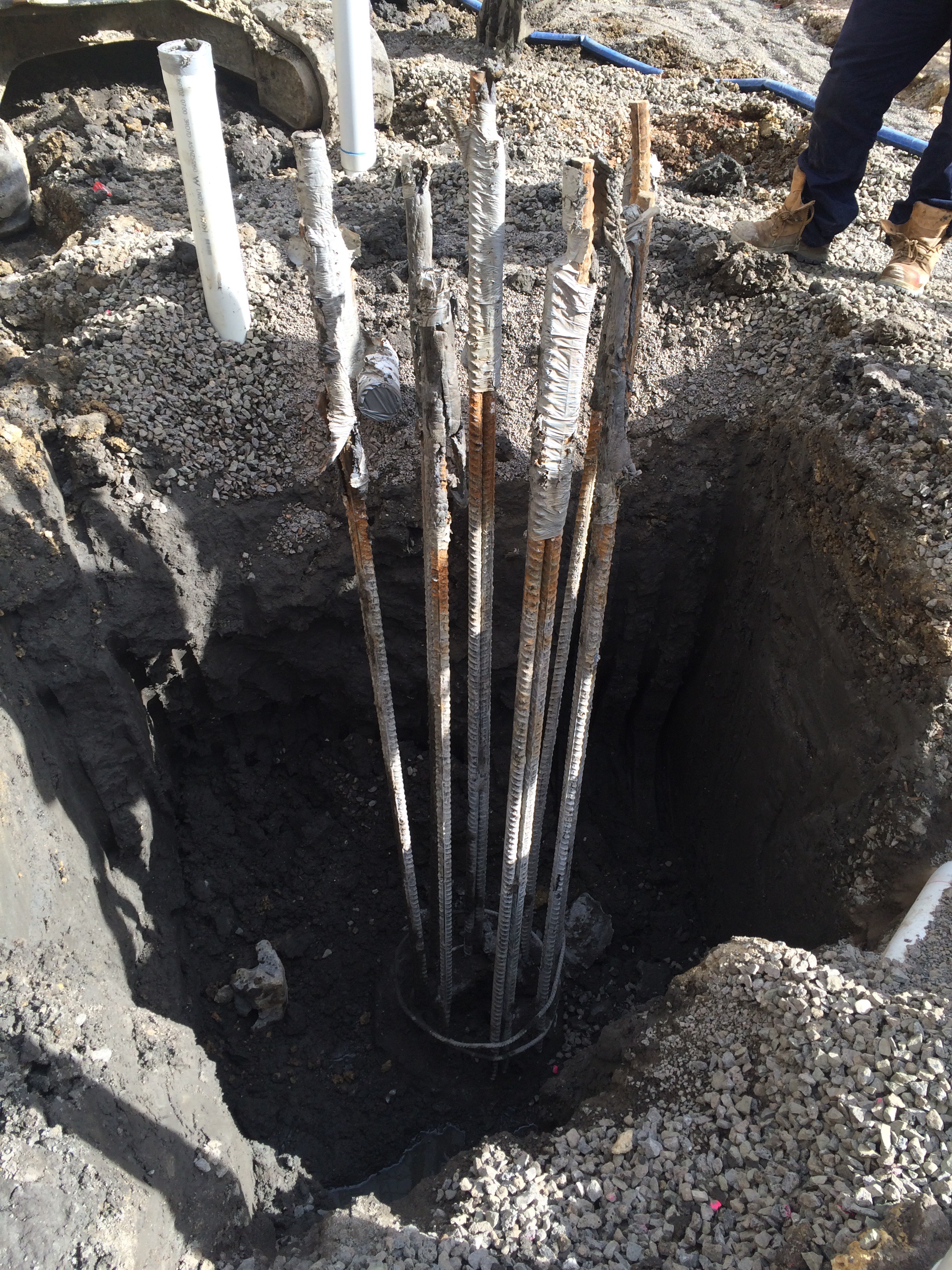
- Pile cages placed too low. Cages installed at incorrect RLs required additional breaking back of piles in 80MPa concrete to locate cage followed by rectification of pile and additional welded bar to ensure correct development length of starter bars.
Recommendations
- Identify the high risk piles using probability vs impact of risk materialising. This will focus QA efforts on the right piles.
- Be specific in the construction methodology about techniques to be used to reduce any ambiguity. Ensure it is followed on site. Measures in the construction methodology are there to mitigate risk.
- Check location of casing of bored piles after drilling before pouring. Out of tolerance piles can be evaluated prior to pouring. Redrilling of the pile now may have less impact on the program than rectification measures to the structure later. (This might be implemented for the piles identified as high risk).
- Use of GPS in the drilling rig will give real-time information on location, depth and verticality of the borehole allowing early identification of casing shift.
- Appropriate identification and classification of soils strata, specifically rock with regard to location and strength. On Australia 108, the basalt was not included in the design stratigraphy for the piles.
- If using polymer, slow and steady extraction rates of the drill reduces the likelihood of suction on the boreholes, reducing the effectiveness of the polymer chains used to support the borehole. If collapse is occurring in soft soils, slow the drilling and extraction rate down.
- Keep polymer levels 1-2m above the ground water level to reduce the risk of borehole collapse.
- Good polymer management is key to reducing the sediment within the polymer; especially prevalent when recycling the polymer from one borehole to another. Reducing the sediment pumped into the boreholes, reduces the need to pump out prior to pouring.
- Good polymer management is key to ensuring the polymer chains are effective. Check the length of the polymer chains dripping from the drill on extraction. Long chains indicate an effective polymer. Shorter chains indicate that new polymer needs to be mixed in.
- Requirement to check the RL of the pile cage prior to pouring. If necessary, the pile cages can be built up above the level of the polymer to check; or the length and laps of the cages be checked and recorded prior to installation.
108 Update
Time for an update on site progress at Australia 108. Lots of progress on site this week. 90% of the piles caps are complete and we have begun the excavation to Basement Level 1. We are 38 days behind the site program due to various issues and delays with the piling as well as lost days due to weather.
The most recent big issue is one of out-of-tolerance as-built piles. The Australian Standards allows for 75mm tolerance however due to the risk in the piles, the designers have allowed for 150mm. So what do you get when you discover that a 2100mm, 80MPa pile with a design axial load of 111.6MN, moment of 16.5MN and shear of 2MN ends up being 401mm out of position? An increase in moment to 49.9MNm; the design effect has greatly exceeded the design resistance of the pile = big problem! The engineers are currently looking at rectification methods involving large transfer beams in lieu of individual pile caps and transferring the addition moments generated to the other piles and the core if necessary. It is estimated to be at a cost north of AUS$400k = 200GBP +. There have been 12 piles over the specified tolerance and with the exception of one, the others have luckily had adequate capacity to resist the additional moment due to the redundancy in the pile with minor rectification measures being introduced to the ground beams.
My TMR is looking into the risk management strategies of deep foundations so once I’ve finalised it, I will post a very abridged version highlighting our issues and probably causes. I know a few of you are soon to commence piling in your projects and can benefit from hindsight of some really simple errors that have been made on this site – most of which could have been easily avoided.
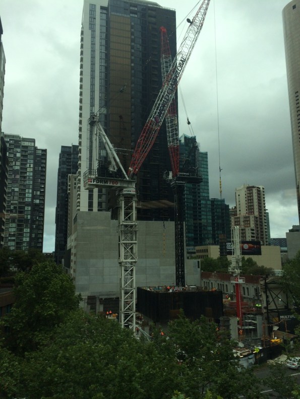
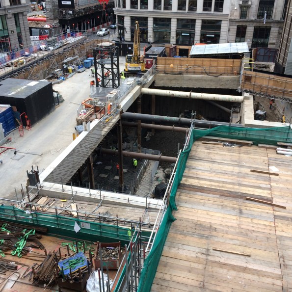
Here are a few pictures to keep you up to date with progress on site.
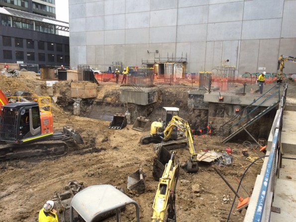
View to the East

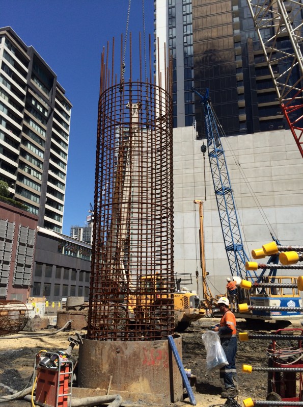
View to the South – excavation of the core piles has begun consisting of 16 x 1800mm king piles with 600mm dia CFAs between

View to the West – secant retention wall to protect a 60 yr old heritage facade at the northern end of the site
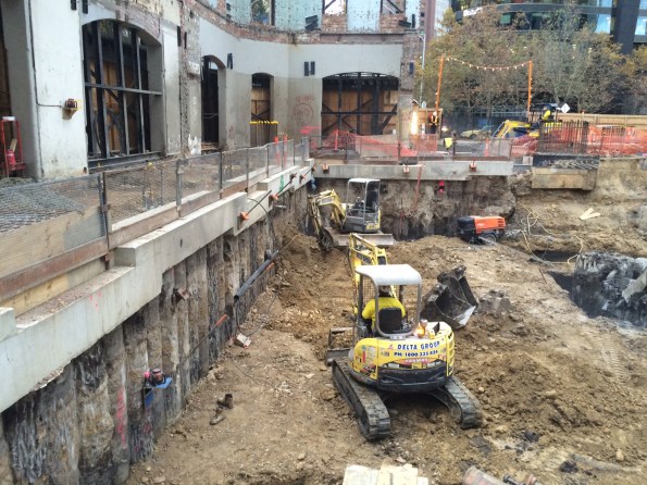
View to the North West – northern retention wall and one level excavation
And for those of you with beady eyes it will not escape your attention the 3+m high vertical face of the southern end to the excavation. Fine grained soils, 30t excavator rolling back and forth on the top of it and no retention or batter. We’ve also had a lot of rain recently (for Melbourne anyway – the news reported a taxi getting flooded out to mid-point of its wheels!!!!!) I have raised this concern to the powers that be and it has already been mentioned to the subcontractor who have chosen to continue as it – because they do it all the time. BMC are allowing them to continue (cynical view – because any changes will slow down progress.) They have instigated no one to walk at the foot of the wall yet people are still walking at the top of it. I’m astounded that they will stop work for the slightest speck of rain because of the potential hazards created, yet they will let people walk along the top of an unprotected excavation. And they are constantly telling me how at the forefront of H&S they are. Barking!
Progress on 12/5/16


Progress of 13/5/16


