Archive
ICE CPR Written Exercise
Last night I attended an ICE event on the Written Exercise (WE) portion of the CPR. It was not a technical seminar or anything of the sort. It was one reviewer, Ian Jenkinson, giving us his opinion and guidance on the CPR in general, but focussed on the WE.
Ian Jenkinson has been an assessor for over 30 years and at some point or another has sat reviews with over 25% of all current reviewers. So his opinion on the review carries a bit of weight and shows a good spread of the opinions of most reviewers.
After the talk I felt much more at ease with completing the WE and taking the CPR on a whole. One of his key points (in the slides) was that the CPR is not an interrogation or a discussion between two adults (reviewers) and a child (us), it is a discussion between three engineers.
The slides you might find helpful, but I will summise a few of his key points here:
- The questions will be picked based on what you say in your report – through this you can essentially set your own questions.
- The reviewer will check you have some knowledge on the subject during the review, if they believe the question is unfair or they have not understood your report, they can still change the questions before you sit the WE.
- When answering the question:
- Do an essay plan (If all else fails and you have cold sweats and palpatations – people have still passed the WE based on a good essay plan
- Tell a story – this is not a technical paper
- They are looking for a good first draft (not polished ICE Journal submissions)
- Use minimal direct quotes and reference them properly – plagiarism will fail you
- Better to use your own thoughts, reasons and communicate them succinctly
- Some examples he gave had typed essays in the region of 1000-1500 words
- Well laid out but no unnecessary formating, front pages etc
- Another key point he made was not to get wound up about the essay. You won’t fail CPR based on a shocking essay, if you fail CPR it is because of the interview session.
- Alternatively, if you have a shocking interview, the WE might turn it around for you (on one attribute…maybe).
- Less than 0.5% of people fail CPR with the WE stated as the reason.
The marking rubric consists of three pairs of characteristics of the WE:
- Knowledge and relevance
- Grammar and syntax
- Clarity and presentation
Questions asked:
- What if the questions you get you cannot answer – Speak to the invigilator and they will help as best they can – he implied that there is always a way to answer the questions they set.
- What attribute do most people fail on – Independant judgement and responsibility. Ian spoke about taking responsibility and saying “I” and what the outcomes and consequences were to your actions. Secondly he said commericial awareness lets people down, but having a base knowledge of the contracts your projects were under would get you 90% of the way there.
His last point, and a slide that isn’t included in the pack was that they are not looking for the ultimate polished engineer, but an engineer who has the potential and drive to become a good engineer.
I hope this helps and sets a few minds at ease about the CPR process as a whole. It would be interesting to hear some of the guys opinions who have been through CPR last year?
Phase 3 – Week 1
At the start of this week I began my Phase 3 attachment with Ramboll in Birmingham. I am working in the Buildings department, currently tasked with an Energy from Waste (EfW) plant in Gloucestershire, this is a power plant that burns non-recyclable waste to produce power (E&Ms can tell you more).
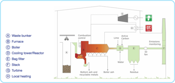
The EfW plant is basically a series of huge steel structures with smaller concrete structures inside them. The loads from the mechanical plant in here pose the biggest issues to the designers, as well as another engineers designing the mechanical systems, they are also responsible for the steel work that supports this. Ramboll are essentially responsible for the housing structure and foundations.
In my first week I have been tasked with looking at the Boiler hall structure. An RC box that houses the turbines and boilers (big loads). The client initially issued loads on the agreement they would not increase by more than 10%. These have now more than doubled and I needed to assess whether the beams and columns were still sufficient at current sizes (increase in steel was presumed).
The critical beam was already 2m deep spanning 13.58m and the column this sits on is 14.75m tall (750mmx750mm). After my week of assessments (by hand) the beam has increased to 2.5m deep and the column is just about suitable. I have also now designed a new roof slab which sits on top of the Boiler hall with some water tanks and other loads.
I think I have just about got through the other engineers watching me struggle with hand calcs and lots of rubbing out, whilst everyone else bashes away at their computers. I will add some photos from the computer model when I have worked out how to Print Screen!
Are all QS mental?
This isn’t directly aimed at Greg Tripp, but maybe he can help me understand why I find myself wanting to dispose of all QS at the bottom of a rotary bored concrete pile!
During piling activities a byproduct of the process is pile arisings, or spoil. In our case this is sandstone (more like builder’s sand). This needs to be removed from site and we have a sub-contractor who is paid to do this.
My first assumption was that when a tipper lorry collects spoil from site and then leaves through the gate, the ticket they leave will be used to quantify how much spoil has been removed. This will then be used to complete the valuation each month for the sub-contractor removing the spoil.
I have been asked by the QS for details on the volumes of the piles as this is actually the quantity they use to complete valuations (not what actually leaves site). I have a number of issues with this:
- What bulking factor is being used – 1m^3 of bank is not 1m^3 of loose.
- Not all material from piling is being taken off site. A large amount is used on site to improve underfoot conditions and the working areas for sub-contractors.
- Other sub-contractors also use the spoil to back-fill in their own areas (where the SES allows)
So I believe the SC is getting paid to remove spoil that is staying on site. When I discussed these issues with the junior QS, he asked me to quantify how much is being left on site – I had a look up my sleeve but was still found wanting on this figure – it’s like trying to quantify the amount of icing sugar in my cocaine.
I see the issues with paying for tickets:
- The tipper lorry may not be full
- The spoil may have come from another location or task
- Tickets get lost
But these issues can be easily controlled; the gate man can confirm the lorry is full (or 1/2 etc). Spoil on site is separated in the tasks it has come from in case of localised contamination. The gate man also keeps a register of vehicles entering and leaving site which will back up lost tickets.
I am yet to consult the QS Pocket Book, but this is my next step. I have so far given in to the QS and delivered the information they have requested.
I have another QS rant where they have specifically gone for a day-works contract over lump sum, because it was initially cheaper – again I argued against this but the QS insisted she wanted all of the risk and none of the security (facetious)…
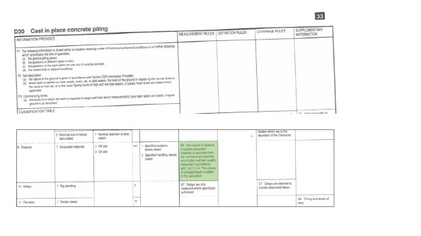
From the Standard Methods of Measurements 7th Edition, the item highlighted in green states:
The volume of disposal of surplus excavated materials is calculated from the nominal corss-sectional size of piles and their lengths measured in accordance with 1 & 2.1.2. The volume of enlarged bases is added to this calculation.
Everyday’s a school day!
Ground investigation by method?
On the Paradise Circus site there are a number of different types of foundations:
- Rotary bored piles (900mm and 1200mm)
- Single pile caps
- Grouped pile caps
- Cantilevered pile caps with tension piles
- Ground beams
- Pad foundations
- Ground bearing slabs
- Suspended slabs
The last two are pushing it, but I thought I would throw them in as they are definitely in the future of this project.
I have been asked to investigate a request by the designer that the location of the Pad foundations be subject to a Plate Bearing test (Carillion are obsessed with these and so seems the industry as a whole – has anyone else experienced this?). The plate bearing test has been specified as a must have to us and due to my protests at this, I was given the task of liaising with the designer.
The need for this test is to qualify the assumptions made during design – happy with that. The test must be completed at the formation level of the pad foundation – not happy with that.
Although the pad foundations are nominally 1.2m deep, the formation level is the Sandstone strata that at it’s highest point is about 3.5m BGL. In order to conduct a plate bearing test there needs to be a technician with the equipment and a machine large enough to create the pressure needed on the plate.
Edit: The distance between the bottom of the pad foundation and the rock strata is made up with mass concrete fill (bonkers?)
I conducted a similar test on a 450mm dia plate at 550kPa and needed a 22T machine to Jack-off – this test has been specified to 1500kPa. Here is a photo of the former.
Take in to account the excavation to 3.5m depth and a safe batter of 1:1.5 (Carillion standard for large excavations) and the requirement to do about 10 of these over the site – we’re looking at basically doing a reduced level dig to the sandstone across the site.
Now I have asked the question “What do you want to know, Mr Designer?” As I said previously, the aim is to qualify the assumptions made during design – these are regarding settlement. The designer has come back at me with “Stiffness”.
I now need a method of finding the stiffness of the sandstone between 3.5 – 10m depth across the site – without excavating enough material to fill Wembley stadium. I have made some suggestions but will keep these to myself for now – what would you have said or come up with?
Piling by estimation
This slide show lays out the basic process to piling at Paradise.
Piling began in Paradise three weeks ago. The piles are 1200mm bored RC piles working in end bearing. Each pile requires a rock socket length of approximately 6D.
Despite the management issues with the demolition subcontractor being currently 9 weeks behind schedule and still on site, the piling has been going well. The target has been to complete 2.5 piles per day and the pilers are currently hitting around 3 per day.
The estimation that the piling is working on is that of the rock head level (m AOD of the incredibly weak and completely underwhelmingly named “Bromsgrove Sandstone”). The rock head level is required 10 days before the piles are installed and this has been assumed based on previous construction drawings that show the underside of foundation levels. This level effects the overall length of the pile and more importantly the length of the steel reinforcement cages, hence the lead time.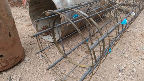
The issue I had yesterday on site was an obstruction encountered below the presumed rock head level. This obstruction appeared to be a concrete slab, possibly blinding, at about 5.5m below piling mat, the rock head should be 4.25m below. A quick inspection of the piling hole identified the sandstone was collapsing above the obstruction and water was trickling in to the base.
The piling designer was contacted and assured everyone that the rock socket length could still be achieved by increasing the depth of the pile, but not the length of the cage, so the bottom 1.25m would have no structural steel. (Revision – due to additional length in the cages the actual length without steel is only 600mm). This pile will be recorded as a non-conformity by the piling sub-contractor and I will advise that further testing be carried out on this pile.
This pile is located in the core of the structure and as such I am now concerned that the surrounding piles will also have a rock head level lower than expected. When we do the surrounding piles (Approx 3 days after that pile in question – Monday) I will be able to get a better idea of what the obstruction is.
Temporary propping of a permanent wall
Temporary works are becoming somewhat of a theme on my site, we are moving in to the construction phase with piles and other groundworks appearing all over. I was asked to assist one of the section engineers with a design clash issue on the retaining wall I have written about previously, here is a picture to jog your memory.
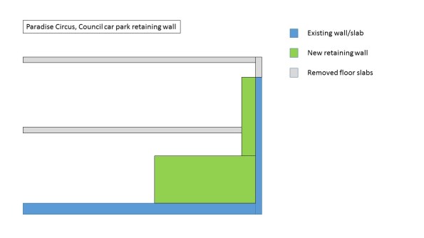 The blue wall has been temporarily propped with two levels of 45 degree square hollow sections that also prop off the existing floor slab. The design was intended to contain the lower prop and the upper prop would be removed, as shown in the Temporary propping arrangement.
Somewhere along the line, a mistake has been made either in the fabrication and installation of the props, or in the design of the wall. The lower prop now protrudes at the corner and is also required to be removed. With the base being poured in two levels (a mass concrete pour and a waterproof topper) these can be removed after the first pour.
Essentially the first base pour will replace the action of the lower prop so these can be removed. Our TW designer has asked the base concrete achieve 2/3 of the design compressive strength (approx 26.5N/mm2) before these are removed. Although in a gravity retaining wall, such as this, what affect does the strength of the concrete have?
I have a theory that the TW designer has tried to mitigate against the concrete being stripped out if it doesn’t reach the required compressive strength after the lower props have been removed. This would leave us up the creek without a paddle, as the upper props could not sustain the loading from the existing wall.
Update:
The props have now been removed and the wall hasn’t collapsed.
Propping against air
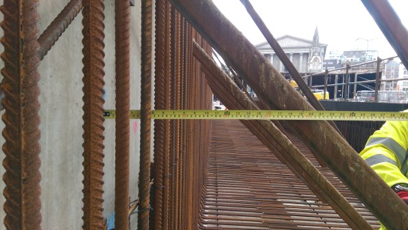
I have been presented with this issue today. The groundwork contractor, Churngold, have been given a package to construct a large retaining wall that will replace a wall which was being propped by a podium deck and intermediate floor slab. See the below drawing.
The wall is being cast in three stages. 1) Mass concrete footing. 2) Waterproof concrete on footing and kicker. 3) Waterproof concrete for wall. Stage 1 is due for completion on Monday 8 Jul.
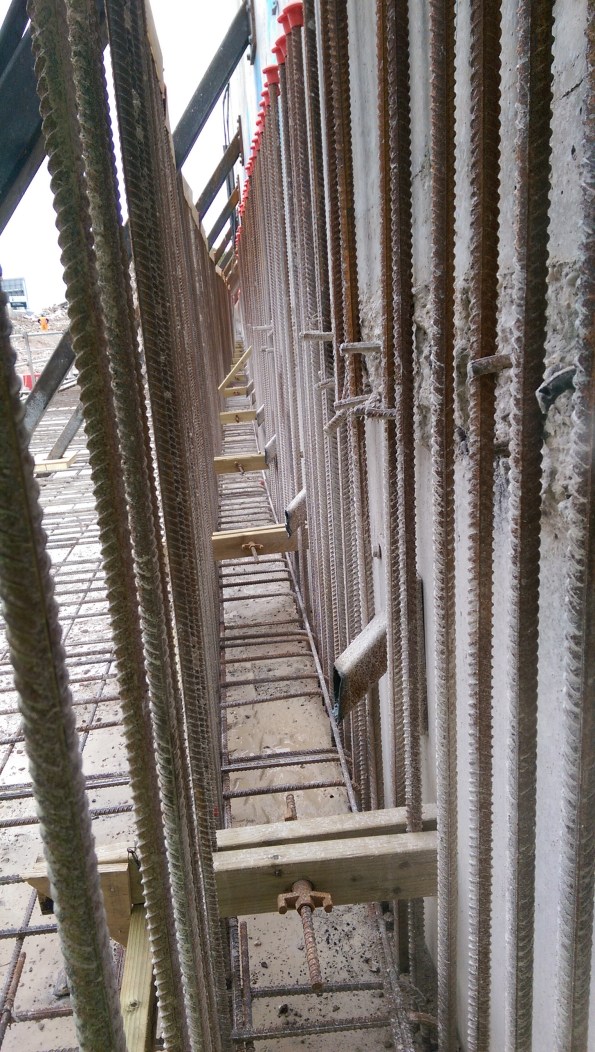
The formwork is a proprietary system from Mabey and requires soldiers at 1.5m centres at 1.66m height and with a leg of 1.6m. See the below photo to identify formwork.
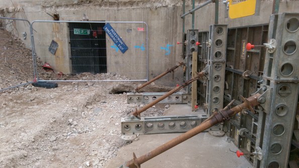
As can be seen in the above photo there is a section of slab that has been removed as part of the demolition works, from which the groundworks contractor were planning on propping against.
My options for the solution to this so far have been.
a) Cast footings where required.
b) Redesign propping system.
c) Cut short pour with a stop end to a safe location where the propping is stable against the slab.
d) Mass pour a slab in the hole and allow the subcontractor to prop against this on Monday.
My initial thoughts are a combination of a) and d) which will appease both the QS and the subby. However I need to satisfy myself that the prop loadings will be taken by the slab under 3 day strength (assuming the concrete is poured on Friday 5 Jul), and secondly that the backfill material will take the load from the slab and prop loadings.
Well, the weather outside is frightful..
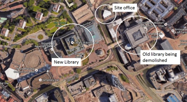
Defects – On our phase 2 placements we rarely get a chance to get involved with any maintenance or defect periods. This week however I have been lucky enough to be involved with a previous Carillion site that was finished in 2013, it helps that it is next to my current site, see Fig 1. The Library of Birmingham is the most visited tourist attraction outside of London, and it leaks like a sieve.
With the storm rains that we have been having, a defect has been identified where rain water is getting under the curtain walling on 2 floors with a terrace level. This is most likely through the service exclusions (sorry E&Ms but you do like to mess up a good impermeable box). I do not know the contract obligations that exist with this previous project, however Carillion have sent a team to control the ingress of water. The plan included puddle pumps, sandbags and cat litter, seriously, cat litter, enough for a pride of lions.
The issues that have arisen now include:
- What is the plan to stop water ingress during future storms?
- What was the design storm used and how did it compare to the weather experienced?
- Is it a design flaw or is there a construction issue?
- What are Carillion doing using a separate project team to fix the issue?
This immediate reaction has bought some favour with the library (Q4), but there will undoubtedly be a redesign and some work completed in the coming months. Watch this space and I will explain the contract obligations and where liability for the works and defects lie.
Up the creek, without a paddle
So, whoever said demolition would be easy, obviously has not visited this site. The newest problem that we have faced involves a nearby hotel (a key stakeholder in the development), a blocked foul drainage pipe and an excavation full of yesterdays dinner!
Last week there was a distinct smell of faeces in a nearby pedestrian street. The PM mentioned this to the Construction Manager and asked him to investigate. The next day, said CM was moved to a new job (polite way of sacking someone in the civilian industry). Therefore the investigation never happened.
Yesterday morning the hotel manager contacted us through the liaison manager for the project to inform us of a drain that was backing up just outside of the hotels loading bay. The hotel is located uphill from the demolition site and the previously mentioned pedestrian street (a pedestrian street that was created as a temporary diversion at the start of this demolition).

The hotel loading bay – In the background the drainage SC
Carillion, being the forward leaning, considerate constructors that they are, offered to investigate. This consisted of a drainage sub-contractor opening a drain cover on the pedestrian street and saying “Oh yeah, that’s full of Sh*t”. They had already identified the bottom of the private drainage run, that was clear, so the problem lay somewhere in between the two. They are coming back this morning to try to jet the blockage and get the flow moving.
Three tanker loads have been removed from the drain to buy some time.
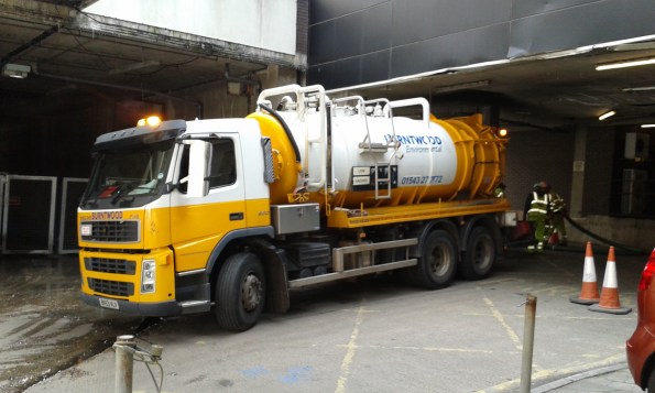
First tanker from Burntwood SC
The cause of the blockage is yet to be established, although we think it was probably the SC who installed the pedestrian street and potentially damaged some of the pipes or left debris inside. However, previous drainage reports from prior to the street being installed, all mention debris in the system.
Votes on causes please:
- Debris from street construction.
- The hotel has eventually blocked it with their own fat/waste from kitchens and toilet paper from rooms.
- The flow has reduced to a level below that required to keep the drains clear. The hotel is the top of the run and it’s occupancy has dropped since demolition started, the office block that also connects to the drain is now unoccupied.
- Other.
In other news:
Laura is pregnant again – due mid November.
I have built a huge deck in my Garden – due May bank holiday!
Some demolition gratification!
So a few weeks ago we had a drone on site to film the progress so far. This is a client directed activity, but something we had to make allowance for on site.
You can probably guess that some of this may not be 100% as per the RAMS.
The tallest of the excavators, an HITACHI Ultra-high reach excavator, is the plant we are having issues with over the tunnels.
Points of interest:
0:12 – The majority of the buildings in this shot will eventually be demolished (except very top left)
0:23 – Ground dust suppression cannon
0:52 – Plant mounted dust suppression cannon
1:25 – Red hose feeding dust suppression cannon (these are quite exposed and often tracked by the plant)
1:44 – Some of the “off-site” works can be seen here, road upgrades and reallignment as part of the development
1:55 – The New Library can be seen here – another Carillion Project which helped them secure this project. (You can also see the Hyatt, the mirrored building, which Andy Bayley has a good story about)
2:10 – This highlights how constrained the site is and why the dust suppression is so important – there is a dedicated liaison manager who keeps all the stakeholders happy
2:35 – The white-roofed, red brick building is currently the site office – although this is going to be demolished
2:45 – The building on the left is the Birmingham Conservertoire (concerts and stuff) and is still in use – more steakholder management.
