Archive
Cranfield high performance computers
A quick blog for those starting Phase 2 and thinking of thesis titles.
A less known about resource available to all PET students is the Cranfield high performance computers. This resource is invaluable if you are wanting to conduct any process heavy computational fluid dynamics (or FEA) using software packages such as ANSYS. Having just used this for my thesis I can highly recommend it, as without it, trying to execute on your own machine is a none starter! In addition, the student downloads that are available from ANSYS have inbuilt limitations on the size of problem you can execute.
If you are thinking about using this resource then more information can be found by searching on the Cranfield intranet for ‘accessing HPC’. You will then need to apply for the Crescent service, which is a dedicated teaching resource to MSc students. Once you have been granted access you are free to use the server.
A basic outline of the steps involved is to develop the model on your own machine, upload to your Cranfield storage, open on ANSYS remote desktop connection, finalise all aspects of the model, save as a .case file and exit, open Cranfield server and follow instructions to load a submission file. Once loaded into the server, there is no requirement to leave your laptop on as it will execute remotely and upload results to your online storage. Download and analyse.
There are other software packages available but ANSYS contains elements of and most aspects of both the C and E&M courses. If anyone think they are going to use it I can share the execution files that I used. They seemed to work ok ….
BP – Vulnerability Strike Team
Since the last update I’ve continued working on Glen Lyon. It appears that it is something akin to Hotel California, in that you can check out – but can never leave. The list of operational vulnerabilities is growing, with many of the top ones preventing production ramp-up to full potential. As it currently stands they are limited to 87mbd (1000 barrels a day) (87*1000*$62.65~$5.5m a day) when they should be producing at 130mbd. The delta created between these 2 values is quite considerable for a daily profit. Since these figures are so great, intervention was required. This is in the form of a ‘Vulnerability Strike Team’ made up of a multi-discipline team of engineers, in which I am the mechanical/project representative. A quick outline of 2 scopes (8 in total) below:
Rundown cooler change-out
The production of crude oil requires cooling from 90degC to 50degC for storage within the offload tanks. This cooling is achieved through 2-off rundown coolers, consisting of plate heat exchangers. Over the past couple of months the pressure differential across the coolers has increased from the allowable of 0.7bar to it’s current level of 2.7bar. This level displays high signs of fouling/blockage. The current understanding is that through the operating conditions which has been used recently this may have resulted in the build up of wax, where the wax appearance level is 38degC. Both coolers must be online to ramp-up above 87mbd. Current options to solve this were as follows:
- Perform a chemical de-wax procedure using a solvent based chemical. This was completed but showed no signs of improvement.
- Accept higher export temperature, as long as it does not exceed the safe working limit of the offload storage tanks. There was even talk of offloading at a higher temperature and chartering a tanker to drive around the North Sea to allow the crude to cool to 40degC so that it can be offloaded in port.
- Change-out the cooler for the spare unit held in storage.
After a failed attempt at option 1 we pulled the trigger on option 3, which was my bag. This change-out required a 16Te vessel-vessel lift (heaviest lift conducted on Glen Lyon since production started earlier this year) which required a sea state of <2.5m significant wave height. It then involved an unknown weight (based upon unknown quantity of wax) of an inboard lift, over live plant to remove the old cooler. Long story short, they managed to lift the cooler but it was 102kg below the allowable 10904kg safe working limit (~99%). This was an imposed limit by the mechanical handling contractor based upon stress analysis performed on the cooler lifting points. Some photos below to show you what I’m talking about.


Heating Medium – leak mitigation
A further scope of work I’ve been SPA for has been the remedial works required to recover from the discovery of unreliable/failed flow transmitters (as described in previous blog). This scope involves the works required to mitigate against the potential of instrument failure of a 16″ and 8″ heating medium line. Both options below are being worked up concurrently:
- Drain down of approximately 25m3 of heating medium, removal of old flow transmitters and replacement with blank pipe spools. This will require a 7 day outage, which would cost them around $30-40m in deferred revenue. This is not currently acceptable but is the base case.
- Engineer an external pipe clamp for mounting over the top of the flow transmitters. This involves a case filled with resin. We are currently working up the control of works required to enable this work to be done while the line is hot, reaching temperature of 110-140degC. The 16″ clamp weights around 800kg so stress analysis of the pipe is required, which is still unknown. The decision was to buy these regardless since if this option is feasible it will prevent a 7 day outage.
To provide a little context I’ve included a couple of photos below showing what the flow transmitters look like.


I guess in summary, something that I’ve not been exposed to before is the realities of the importance of production revenue. The vulnerabilities we are currently working on will hopefully help Glen Lyon reach its potential of 130mbd, bringing in ~$8m a day. The pace of life is very different to planned project delivery, but it makes things far more interesting anyway. Although there is currently no time for thesis….
BP – Glen Lyon flow transmitters
Just thought I’d provide a quick update on a piece of work I’ve been doing recently on the brand new Glen Lyon floating (is a ship), production (includes an oil rig), storage (capacity 850,000 barrels) and offloading (requires tanker to come alongside), or FPSO for short.
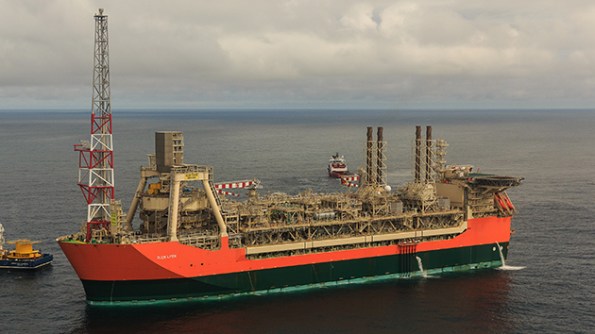
Glen Lyon FPSO
I have been drafted into the Operations engineering team to project manage an issue which happened last week. This issue relates to the gas turbines (GT), of which there are 4, and the Waste Heat Recovery Unit (WHRU), one per GT. A brief synopsis is as follows:
At approximately 1500 on Friday 27th of October, whilst producing circa 100 mboed (1000 barrels of oil equivalent) and during stable operation, a shutdown signal was sent from GT2’s WHRU flow transmitter, initiating a GT2 shutdown. This resulted in a number of cascade trips that eventually caused a production shutdown due to complete loss of FPSO main power (a separate issue currently under investigation).
On initial investigation it has become apparent that GT1, GT2 and GT3s WHRU flow transmitters have all degraded and began to physically leak externally at approximately 50-60 drips per minute. The subsequent failures discovered over the W/E of 28th – 29th October have left Glen Lyon with only 1oo4 GTs availability and unable to ramp up production as a result of the failure.
This is clearly super bad for BP’s flagship asset, which is one of its highest produces. This clearly attracted a lot of attentions from VPs etc. I became involved at the request of the asset for support to project manage the recovery of the WHRUs and the switch over to main power. The immediate issue was the recovery of at least 2oo4 GTs which are required to provide power to the main thrusters to provide stability during an offload to a fuel tanker. By delaying the offload there is a deferral in potential income for the oil that is not being exported. The issue was compounded when a potential procedural issue caused the bursting disks to rupture on the cooling medium system on the only working GT.
Before I describe the options available I’ll explain the flow transmitter layout. Each WHRU has 1 flow transmitter which consists of 16 off transducers which are circumferentially mounted on a 10”pipe (providing 16 potential leak paths). See photo for what these physically look like.


The immediate short term fix was to drain the system, remove the transducers and plug with a standard bolt (short plug) and dowty washer arrangement (see photo). This was the quickest, but the most temporary option available. This was completed for GT3 on 2nd November.
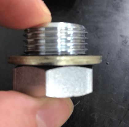
Short plug and dowty washer
The second, and preferred option, is to machine new housings from solid 316L stainless steel, using the dimensions from the original transducer manufacturer. These were expedited for GT2 but failed to fit due to a ‘tolerance’ issue (they were within tolerance so we think they might have messed them up!!). We then had to revert back to using the short plug option which was completed 4th November. This allowed us to run up 2 off GTs on diesel and offload c.200000 barrels to the tanker. The problem with using the short plugs is that they notionally have 2 week expiration on their suitability, which will then need to be changed out for another option. At the present time the machined housings have been re-machined and sent offshore on air freight. The plan is to plug GT1 and GT4 with these.
As a further contingency, 4 off pipe spools have been manufactured which will replace the flow meters and remove the risk of any leak paths. These spools had a lead time of 10 days but will require to be shipped by boat. The current weather is causing issues with offloading as it is a boat to boat lift. These are likely to be offshore next week.
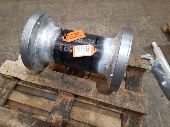
Pipe spool – 600m length c.125kg – must be shipped by boat
The initial headlines have died down somewhat since the main power is back on, the offload was successful and the plant can begin to ramp up production. It has been an interesting experience to be involved in crisis (project) management. The way forward now is to conduct a root cause failure analysis on the transducers to provide a long term solution. Depending on the time required for this, the immediate plugging solution will require change-out for an intermediate solution, likely the pipe spools. I’m likely to be involved in this for the next few weeks at least, with a business call made on my other projects to put them on hold.
BP – pipe support loads
Alongside project delivery I am currently working as part of the mechanical discipline engineering team. The work I am doing for them is answering Design Technical Queries (DTQ) and Engineering Queries. I started trying to explain both but it became too wordy, the DTQ is explained below:
A DTQ was submitted in relation to the pipe support loads experienced during a blast event along new production flowlines that are due to be installed (some have actually already been installed). The Clair platform has legacy issues relating to blast whereby the original platform design was never designed for blast. As such, all current in-use flowlines and pre-invested (installed but not hooked up) are supported using standard U-bolt pipe supports. The U-bolts are not designed to be able to withstand a blast event since the primary load path for the bolts is vertical. The U-bolt manufacturer only specifies a max vertical load therefore a max lateral load must be assumed.
Wood Group are the contractor designing the new flowlines (to be tied into pre-invested) and are concerned that in the event of a blast a number of the pipe supports will fail due to excessive lateral loads. Their basis for this statement is a rule of thumb that the max lateral load is a nominal 30% of the max vertical load. The manufacturer stated max vertical load is based upon the yield stress of the material. They have asked if they are to replace all the pipe supports since they all fail.
Recognising there are platform wide issues relating to blast, Fraser-Nash Consultants (F-N) were contracted to conduct targeted blast analysis on a complete flowline (one designed IAW original platform design). By modelling the U-bolt failure load using a similar method as Wood Group, F-N came to the same conclusion that the lateral loads are excessive. In order to understand the actual post-yield material characteristics (ie strain hardening etc.), a nonlinear analysis was conducted based upon the U-bolt geometry and material. From this they were able to establish a plastic collapse load. When modelled in this manner all the U-bolts were found to remain within the plastic collapse load. The picture I’ve attached kind of explains this problem through the stress-strain graph.


My response to the DTQ was initially to accept the F-N analysis since the U-bolts do not collapse fully, maintaining some structural integrity. My justification for this was that the design event is blast, a one-off whereby the performance criteria is to maintain primary containment. No-one seems content with this response and I am now stuck trying to provide more justification, any ideas?
Static mechanical update
This is just a quick update since my last post on the projects that I have been delivering.
Hydraulic fracturing hanger – static mechanical
This project was the main focus of my last post and is nearing offshore construction. We managed to reach all the construction deliverables, a fairly simple task since it is a single discipline, static mechanical project. This was key since the asset can turnaround and refuse your construction window based upon readiness of the task. I’ve included a couple of photos below to show the location of the hanger in relation to the asset. If you look closely into the yellow box you will see the thredders bloke who has to escort the drone pilot around.


The key issues associated with offshore construction will be the removal of the heavily corroded bumper bar, contingency is the use of hydraulic jacks to persuade out of the sleeves. I’m currently luckily enough to mobilise for the days leading up to the construction but because of flights cannot stay on the platform. The offshore single point of accountability, during the construction phase, falls to the Maintenance Team Leader with daily VCs with onshore to update on progress and issues. This is particularly difficult since, unlike most of you, I cannot nip outside to go and see the problem.
Clair Low Temperature Modifications
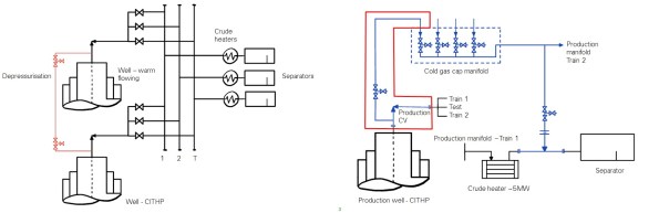
I’ve recently kicked of a new project which involves the installation of low temperature rated pipework to depressurise the wellhead following a period of shut-in. When the well is shut-in, for emergency or maintenance reasons, a gas cap forms a Closed in Tube Head Pressure (CITHP) of around 160bar (bad). If you were to depressurise this in the existing pipework the temperature would reduce to around -70degC (bad) and cause low temperature embrittlement (bad). The temporary solution, shown on the left below, was to depressurise this through flexible hoses into a known warm flowing well. This practise, while functional, was deemed unsuitable due to the requirement to break primary containment. It also took around 5 days to complete. The permanent solution, shown below on the right in blue, is to install low temperature rated pipework to depressurise, through a manifold connected to all wells, into a warm fluid downstream of the crude heater. Phase 1 of this project was completed in 2015 with Phase 2, my project, installing the pipework to tie-in 4 wells into the cold gas cap manifold. Complexities include construction priority vs asset priority, securing dates in the asset plan, while working up the engineering in a relatively short time frame.
Discipline Engineering – blast analysis
Unlike other phase 2/3 attachments, there is an opportunity at BP to conduct the phase 3 element alongside phase 2 work. As such I’ve recently started a piece of work which is to answer a technical query raised by Wood Group. This TQ queried the levels of blast, if any, which should be used when designing the new flowlines of recently drilled wells. A comparative study was conducted by Frazer-Nash which compared the methods used by 3 popular contractors used by BP. This study highlighted the lack of standardisation through interpretation of the design guidance. Frazer-Nash have subsequently conducted their own blast analysis of high risk areas of the platform which resulted in all elements of the flowlines and supports failing in both elastic and plastic tests.
My job now is to interpret the results, linking this to the Quantitative Risk Assessment, to decide what the effect of not design/designing for blast and to what level it should be accounted for. I don’t know anything about blast.
Note: Static mechanical was the term used by a structural engineer when describing his job. I think it’s an in joke.
BP – Hydraulic fracturing hanger
Blog summary
I’ve been at BP for around 7 weeks working in the Projects & Modifications team. Unlike most other Phase 2 attachments, the BP one is slightly different. The overall ‘project’ doesn’t always exist as they are often carried out on a discrete basis, but, like all brownfield offshore engineering, it requires a lot of interface management with the core business of production, and other functional areas of the organisation (reliability and maintenance, wells, inspections etc).
I’ve recently taken up a project which involves the fabrication and installation of a hydraulic fracturing (frac) hanger to connect pipelines during a frac campaign of 4 wells. This is a purely structural project (even though I’m E&M!) but was given to me as it is being fast tracked through the project life cycle to meet an offshore construction date in July. The discrete nature of the project allows for sole ownership under direction from the asset programme manager. The scope is simple but allows exposure to the various stages of the project life cycle in a short time frame, while interfacing between various departments.
Background
The frac hanger is to be installed on to a laydown area of the platform which will allow for interface between the frac vessel and the platform. A 4” co-flexip pipeline is to be lifted in to position using the platform crane and connected into temporary flowlines located on the platform. This interface allows the vessel to pump large volumes of frac fluid down the well to initiate fracture. It will be used for the duration of the frac campaign and removed thereafter. There is not much requirement to chat through the design but I’ve added a picture of the proposed solution and an example of a ‘landed’ co-flexip style pipeline onto a frac hanger. The 3 pins are the interface between the hose and platform. An offshore survey is currently on going to confirm the exact scope of works required, but will probably include a destruct of a side panel and a construct of the frac hanger and new side panel. The hanger is designed to support the worst case scenario, 8.1MTe, of an emergency release of the pipeline from the boat end. Structural assessments have been carried out on the frac hanger and global structure of the platform. These are to be reviewed by a BP structural discipline engineer before approval for construction is granted.


Commercial
The well is co-owned and therefore when something, such as a frac campaign is scheduled, it must have agreement from all parties and will generally be co-funded accordingly. This is unless one party is willing to solely fund the operation to boost the production levels. In this instance, however, this is not what is happening. A third party contractor is funding the whole operation in return for a percentage of the production for a number of years. They are therefore carrying the risk of a non-increase in production (possible), while BP profit from the campaign if this isn’t so. That being said, the actual costs for engineering are fairly straightforward. The frac hanger is being constructed under the Engineering, Procurement and Construction contract that BP have in place with Wood Group (WG). WG will submit an estimate for all aspects required to get the frac hanger in place, BP will pay them while the third party contract will reimburse BP. Simple. I have no appreciation for costs in the construction industry but £250k for what is standard UBs and stock steelwork seems quite a lot.
General offshore construction observations
If you have got this far with reading, well done! I’ll finish off with some general offshore construction observations.
- Offshore construction scheduling is driven by the number of persons on board (POB) on the platform. There is a requirement for a number of ‘core crew’ to continue with production at all times. There is then a float above this for any others that may be working on the platform, with a self-imposed maximum POB (less than the beds available). This is then further constrained by flight frequency to the platform. In order to secure POB the requests must go through levels of authorisation at 12, 6 & 2 week gates, with the risk being accepted by the ‘gatekeeper’. Sort of like Gandalf on the bridge of Khazad-dûm. The ‘bums on seats’ on the flights must be confirmed at the 2 week gate. Below is an example of a platform POB level. In short, everyone requires POB and it is the asset planner’s responsibility to ensure that the correct POB are on the asset at the right time. This often means projects being delayed until areas of lower POB.


- The BP contract with WG is well established and works well. Value for money, probably not, but I’m not sure anything in oil and gas is. When WG are given a SoR they will engineer, procure and construct everything that is required. They have project and asset programme managers who are responsible for the delivery of the project with embedded construction supervisors on the platforms. Most of the onshore positions are also replicated on the BP side too! There appears to therefore be an element of ‘man-marking’ when it comes to the delivery of a project, however, the BP side is acting more as performance managers than project managers. That doesn’t mean you can sack all BP project managers, where they become invaluable is the integration with other functions within the organisation. This is key when ensuring that the project is actually delivered as they are rarely conducted without the help of the platform’s core crew. This is particularly difficult to understand when new to the business as decision rights aren’t always that straight forward.
I’ll look to blog when anything exciting happens, but in the mean time I’ll just explain other works areas I find myself part of.
- Construction of 4 lots of new choke valve pipework. I haven’t actually received the scope yet so nothing more is known than that!
- The appraise/select for the increase of 2 x electric heater capacities to allow 3 gas turbines to be run simultaneously on the platform. This involves selecting the best option based on estimates conducted by Costain and the technical knowledge of the various process, electrical, mechanical etc. engineers.
