Archive
Coronavirus contract webinar
I was provided the following link to a Coronavirus contract webinar (1 Apr) from Turner & Townsend who are quantity surveyors for one of my work’s projects.

Everything I have seen so far seems to suggest that it is likely companies under JCT will seek a force majeure event, potentially receiving additional time but not money. Under NEC it looks like clause 19.1 – prevention. This being an event which stops the completion of works on time, that that could not of been prevented or foreseen. This would link to a compensation event under clause 60.1(19).
The Built Intelligence website seems to have quite a few other interesting free resources which could help people looking for some CPD.
No longer being on site it is harder to get a handle on how the issue is being dealt with. It would be good to hear what other people are experiencing.
Temporary works design – MEWPs
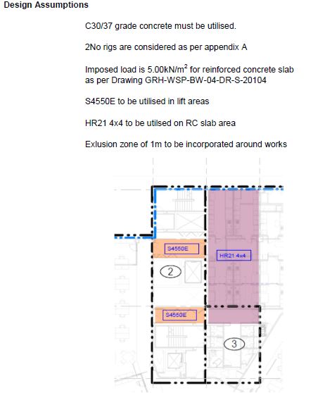
General. I have been reviewing the temporary works design that we have received on site for the use of some MEWPs on our suspended slabs. Two different MEWPs are to be used, one at approx 35.9 kN when loaded with a small footprint (1.25×2.22m) and a larger version, 69.3 kN when loaded with a footprint of 2.27×5.47m. The maximum slab span in the working area, is a two way spanning 9.48×6.4m with a qk of 5.95 kN/m2 and 6.9 kN/m2 in the smaller area shown below.
Temporary works designer (TWD) assumptions
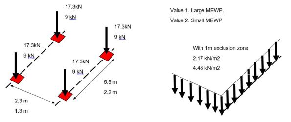
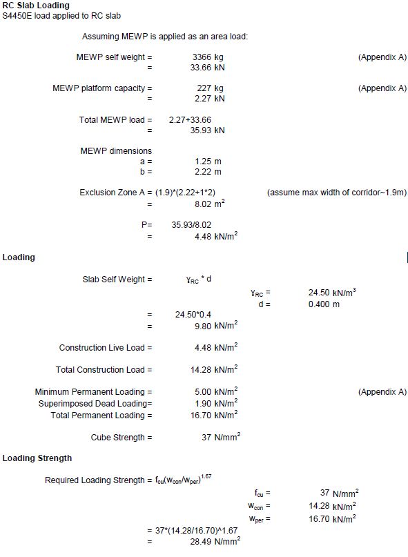
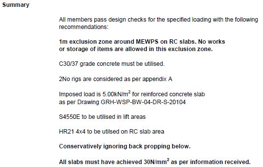
Method. I initially did some conservative calculations applying the combined load of two wheels at the mid span compared against the design UDL to check the TWDs value. The temporary works designer however has applied the MEWP as an area load with the addition of a 1m exclusion zone around each one. They then verify that this is less than the permanent loading before stating the loading strength required of the concrete. Note the loading strength is not a concern as the slabs have reached their permanent strength.

Limitation. An exclusion zone is normal around a MEWP however as work progresses equipment and furniture may already have been installed and so the surrounding area may not be completely clear. Also note the smaller MEWP must work in a corridor so a smaller exclusion zone has been included above.
TWD summary
Question. Is it appropriate to apply a vehicle load as a UDL in this way (this reminds me of the UDLs/tandem systems we used in bridge design)? Should alternative load models have also have been used to check this was the most onerous version?
Constructionarium
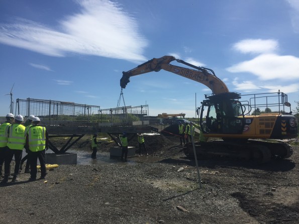
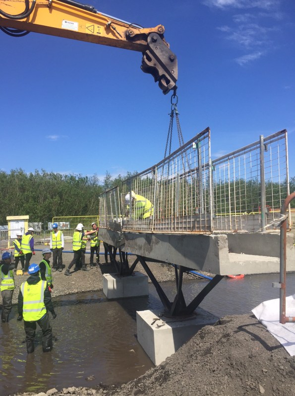
Summary. I recently attended Constructionarium in central Scotland on behalf of Multiplex. Here I acted as a client/mentor while Civil Engineering students from Glasgow University constructed scaled down versions of infrastructure and building projects.
Background. The scheme is ran across the UK with a large number of universities and companies sending their students/graduates on it to develop practical construction experience. Teams of approximately 12 are split into roles from project managers, setting out engineers and quantity surveyors and are given a set of drawings and specifications for their allocated project. Alongside their allocated role they act as operatives while skilled assistance is provided by the training supplier such as plant operators and appointed persons.
Detail. The event runs Mon – Fri and all the materials and equipment are provided by the supplier. The team are not however informed exactly what they need and so it is amusing to watch them level ground with shovels for 3 hours before realising they could have requested a light wheeled tractor. It is encouraged that the students are left to make mistakes as part of the learning process and simple problems like failing formwork provided platforms for discussion on structural analysis. They are required to produce RAMs, obtain permits to work, conduct toolbox talks, inductions etc all in line with realistic outputs of a competent contractor.
")
")
Military relevance. Constructionarium Scotland is a non profit organisation and the director was keen to promote its potential value as a training method for the military. I have summarised some pros and cons below:
+ All inclusive cost for 1 week training is £150-200 per person (including lunch, eqpt + materials – minimum numbers are 20 people). For context, 1 week pre deployment training (PDT) in Chatham for a B&SF costs approx. £750 per person.
+ Training can be tailored to suit learning objectives. For example more experienced tradesman can be pushed in areas of planning, health and safety, resourcing etc.
+ One stop shop would make planning of the training straight forward. Site is clear, free of contamination and includes welfare facilities and security.
– Obtaining financial approval for training from Brigade may be difficult, even if justified as PDT.
– Greater value was achieved through higher training numbers, for example we had 54 students and they could learn from different projects. Engineer regiments may struggle to get this amount of manpower available for additional training.
– Experiential learning training benefits are harder to articulate than straightforward courses. For example a week’s PDT at Chatham for a B&C may include a scaffold ticket whereas Constructionarium did not include this type of validation.
– PDT may be better utilised practising construction directly relevant to the projects to be undertaken on deployment.
")
")
Engineering surveying
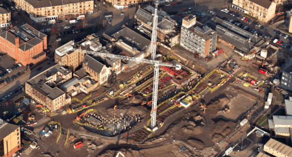
Introduction. I am now in week 3 with Multiplex on the University of Glasgow campus development, working on the £80m Research Hub project In general, the structure is a 6 storey reinforced concrete frame using flat slabs, piled foundations, steel frame roof level, pre cast concrete cladding and curtain walling. Piling finished in February with the rest of the substructure works in progress.

Issue. Along with the site engineer I have been looking at ways to improve the efficiency of our construction layout surveying. Particularly our methods used to control elevation, horizontal position and dimensions. At present we use a co-ordinate based setting out system with a Leica Total Station and are looking to improve our workflow prior to conducting as builts and setting out of MEP systems. At the moment 1 of 2 methods is typically used:
Method 1 – The junior site engineer is using a manual method. Using a dimensioned drawing, offsets from gridlines are calculated then checked on site using a reference line function.
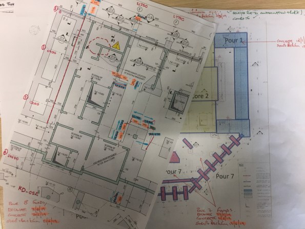
Method 2 – The senior engineer has been replicating the project Revit model for the element, then exporting the lines to Autocad. From here the intersections are exported as a CSV and checked using the stake points function.
Neither method is ideal and so we have been looking at 2 alternatives.
Alternative 1 – Leica Building Link. This allows points to be added directly to the federated or structural Revit model. These can then be exported as an XML onto the Leica and re imported on completion to provide as builts.
+ Free, easy to use.
– Only compatible with Revit 2017, manual input method creates user error and is time consuming.

Alternative 2 – Autodesk point layout. Similar to Leica Building Link this can add points directly to the federated or structural Revit model. It has an automatic function and ability to create naming conventions.
+ Can quickly generate large numbers of points (possible to tie in with Revit families), compatible with Autocad and Navisworks, can create slab analysis heat maps.
– Relatively expensive, more complex to use compared to Leica system.


Further considerations:
Trust. Do we trust the federated /structural Revit model? It is seen as the point of truth but may contain errors. Therefore is it better for the contractor to produce their own model to identify buildability issues in advance? This can then be checked using clash detection.
Best practice. This Autodesk seminar video outlines the use of a point layout approach by a contractor in the US (https://www.autodesk.com/autodesk-university/class/Best-Practices-Utilizing-Point-Layout-2017#video). They discuss the benefits of system but note that it has taken years for them to optimise the way they integrate it and to design a workflow process.
Summary. Our current methods of engineering surveying are inefficient with room for improvement. Does anyone have experience of similar issues or advice on successful methods used in the past?
