Archive
AEH.. “INFO ONLY”…
Hello folks, just a short, sharp snip it of some interesting bits going on in the design office here in Sydney’ M4 East motorway project. Clearly, those two terms are rarely linked but today I think they make the cut.
“Info Only” – Interesting proposal by AEH (AECom & Hyder JV)…Clear lack of comms…
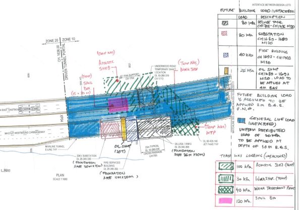
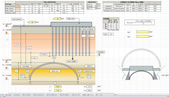
Attached below are two images. 1. Plan of mainline tunnel with surface loads indicated. 2. A screen shot showing the proposed AEH foundation design within a section of mainline tunnel I was analysing for crown loads and canopy tube design. The confliction with our 4m rock bolts emanating out from the tunnel lining is not show.
AEH released their package today for various permanent M&E structures to be installed above the tunnel. I’m in the process of assessing the shotcrete lining thickness and elephant foot dimensions based upon surface loads, overburden, relaxation, ground water etc… The original idea was to install a raft foundation which we were more than happy with (10.5m above). The fact that they now wish to terminate their piles 2m above the crown of the Westbound mainline tunnel is one thing… the fact that they only put Macmillen Jacob Associates (MJA) down as “INFO ONLY” on the cross discipline review form is another! Unbelievable…
Presumed next step..Cost analysis to compare the additional excavation + lining thickness + time+programming required to support new proposal vs an reconsidered AEH foundation design. Interesting stuff but clearly not my main priority at the min…
From Cowboys to City Slickers
-
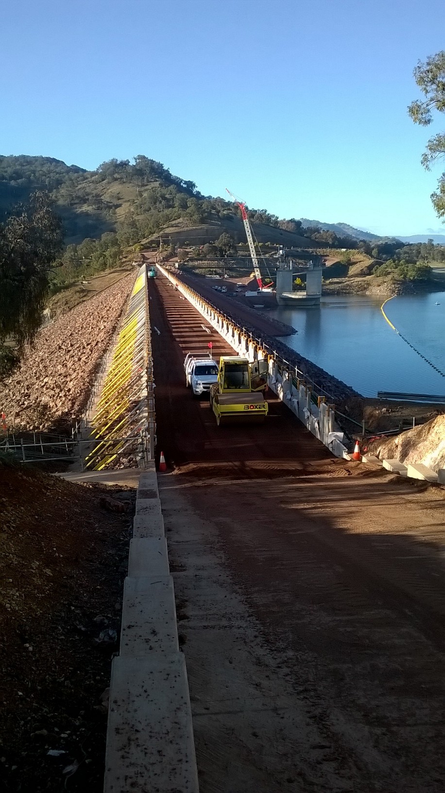
Phase 2 – Completion of Chaffey RE Wall
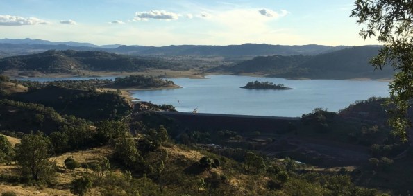
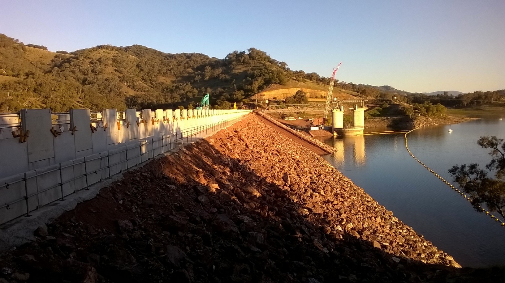
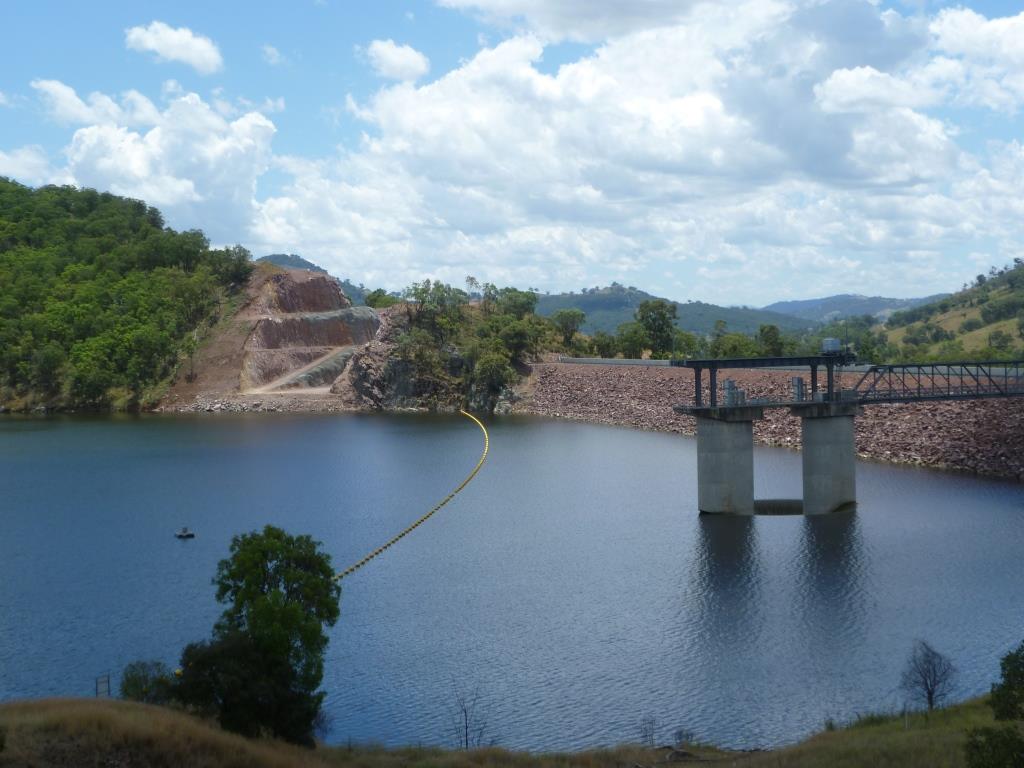
Photo 1 – Southern View of Chaffey Reservoir
In my last week on site at Chaffey Dam I was able to witness the completion of the final layer of soil placement after having laid the very first facing panel seven months earlier. The Chaffey Dam RE Wall was used to increase the crest height of the existing embankment dam to withstand the PMF for the catchment and currently stands 6.9m in height, 7.22m wide and 502m in length. With crest roads works still be complete the final crest height will be 7.2m.
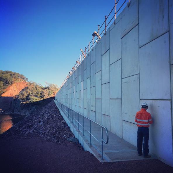
Photo 2 – Upstream Face of Completed RE Wall at Midpoint
-
Crest Works
Prior to my departure the crest works were well under way. Upon completion, the crest was to be used as a service road and so comprise of a bitumen sealed road with combined guard rail/ handrail on the downstream face. On the upstream face, the original 1.7m high pre-cast concrete parapets (or ‘L” panels) were to be installed.
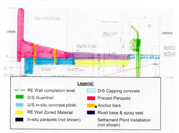
Fig 1 – Typical Crest Section
-
Vibrating Screed Rail
To support the precast “L” units, a 500m concrete plinth (6m x bays) was required. As access was difficult due to the close proximity to the edge of the RE Wall it was proposed that a steel support frame was designed to support the vibrating screed.
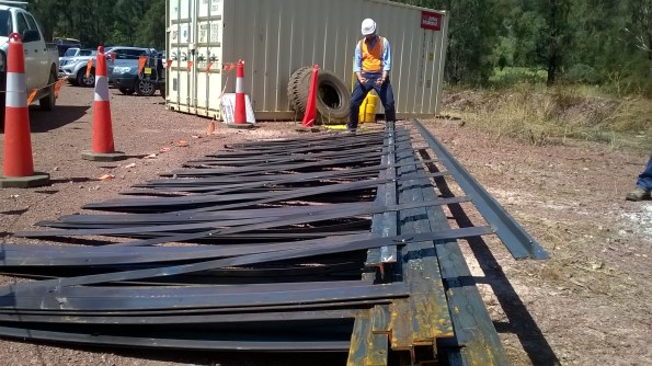
Photo 3 – SPE Having a Moment after Stubbing his Shin on my Screed Rails

Fig 2 – Typical Plinth Section Detail
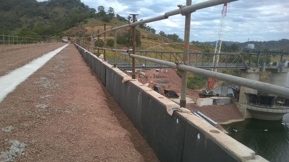
Photo 3 – Proposed Plinth Location
For simplicity, cost saving and time the steel rail concept was pursued. I assisted in the design, procurement and installation of the simple vibrating screed rail. Following review by the SPE and PM the proposal was accepted. Designs were produced and placed to tender across local steel fabricators. Essentially, it was designed to perform as a guide upon which a vibrating screed could be employed whilst also enabling the construction of circular voids within the fibrecrete slab (to allow subsequent HDG steel dowel placement). Geometrically, the simple steel frame was a perfect fit, however the structure was not without fault. The slender steel strips sagged greater than predicted. The strips were simply required to align white PvC conduits vertically, (allowing a circular voids to be created). To counter the bending, the 5mm steel strip could have been either increased in depth in order to reduce the slenderness or even reinforced with an additional steel strip along the axis. Unfortunately, rotating the strips 90 degrees was not an option due to the functional requirement.


-
Fibre Crete

Photo 4 – Example of Fibre Reinforced Concrete
As part of the crest completion works for the Chaffey Dam Augmentation and Safety Upgrade(CDASU) a 500m, concrete plinth (83 x 6m bays) was required to support precast concrete “L” panels on the upstream face of the dam. Due to the unusual geometry of the plinth (see Fig 2), the reinforcement was not straight forward. It was to comprise of 3 individual sections of steel due to limitations in the bending of the steel and logistical constraints. I therefore conducted a comparison between the use of a typical reinforced concrete slab using rebar and Steelfix (Hanson ready-mix fibrecrete). My research concluded that whilst the fibre reinforced concrete will reduce the effects of plastic shrinkage and a negligible increase in the materials tensile strength, it typically should not be considered as an alternative to well placed concrete and reinforcement within structural concrete fibre-crete.
However, for application in question and the relatively low loadings, fibrecrete was deemed suitable. In addition to the structural properties, it was assessed to to better value for money as construction time was significantly reduced and crucially, it did not required the high logistical costs associated with several tonnes of pre-bent steel reinforcement.
-
Countering the Effects of Differential Settlement
The deliberate variation in RLs between the surface of the crest at the centre and the dam and the abutments was approximately 250mm upon completion. The raised central portion was designed to allow for the differential settlement expected. As a clay core embankment dam is constructed, the partially saturated soil is compacted and consolidates as the water is expelled. This results in a reduction of volume of the soil mass.
As Chaffey Dam is constructed upon a rock foundation, it is the profile between abutments that will initiate the differential settlement. By this, I mean that the geometry of the void between the two embankments will result in a varied reduction in volume of clay core as you move across the dam (see figures below).
It is the differential settlement that has the potential to initiate lateral cracks within clay core of the embankment dam due to the tension that will develop in the dam crest where the foundation profile differs. At such points where a significant settlement differential exists, hydraulic fractures may result due to the low stress zones created along the surfaces (see fig below). Consequently, uncontrolled water flow may occur between the upstream to downstream of the structure…not ideal in a dam. Fortunately, most embankment dams experience 80 – 90% of the total settlement during the construction. Consequently, the stresses established in the construction phase assist to control the likelihood of low stress zones and cracking.

Differential Settlement initiated by Dam Profile

Differential Settlement initiated by foundation material
-
Leaving Chaffey
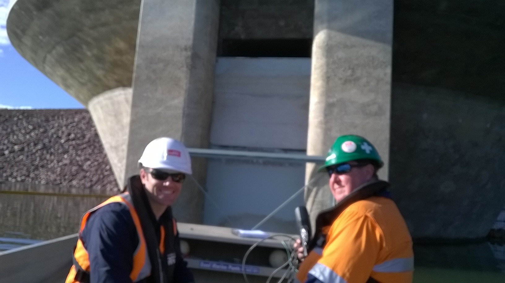
Photo 5 – “Special” Engineers at Chaffey

Photo 6 – Placement of the Final RE Wall Panel
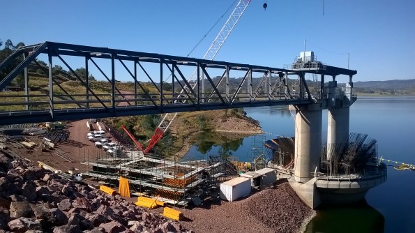
Photo 7 – MGS Construction Feb 2016
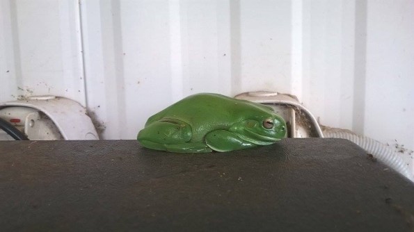
Photo 8 – Definitely NOT the Boolarong Frog that Delayed the Project by 5 years…
-
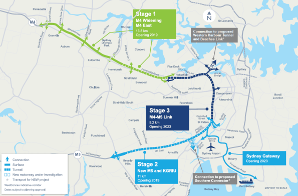
PHASE 3 – WestConnex M4 East Project
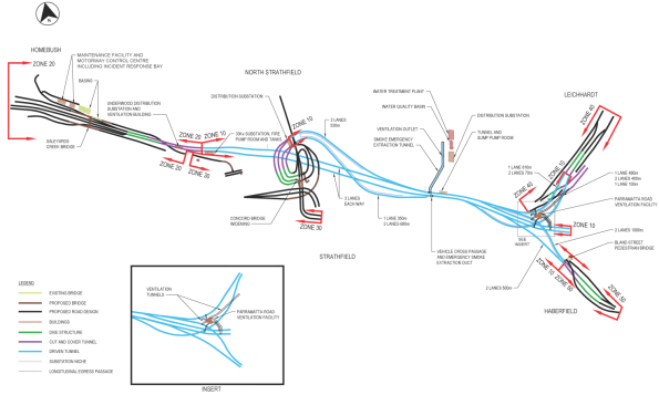
For my Phase 3 placement I am working on the WestConnex M4 East Project in Sydney. It is being designed and constructed by the CPB Samsung John Holland Joint Venture (CSJH JV). The M4 East Project will comprise of two new, three lane carriageways of which 5.5km runs below the city. Several access sites are to be installed along the 5.5km stretch to allow concurrency of works, enabling the removal of earth at multiple points. As such numerous cut and cover structures are to be installed.
My Role – Temporary Works Design Coordinator/ Designer
The schedule for my phase 3 attachment is broken down into three periods. Initially, I will be employed as the Temporary Works Design (TWD) Coordinator before working within a civil design team (AEH), a structural design team and finally a geotechnical design team (PSM). For the TWD Coordination role, my key duties are listed below but essentially the position will offer exposure to project-wide activities, enabling an insight into a broad variety of design packages, the overall design process and interaction with designers and PM’s leading each area of construction. Within each area, numerous works packages are raised which must go through a series of comprehensive design stages prior to release for construction. It is my responsibility to coordinate all aspects within each package, reviewing it at each stage before releasing for both internal and external review.
As I transition to purely conduct design I will focus upon one of the works package which I will have previously initiated as the TWD Coordinator. The proposed works package has been chosen due to the variety of engineering within. Essentially, it is a confined area of brown field site with varying levels which includes a haul road, a settlement pond, a portal frame acoustic shed containing a 7 x 7m vertical shaft and is in close proximity to housing and primary road. Initially, I will be analysing the portal frame and foundations before moving on to the shaft design with the geotechnical team.
Primary Responsibilities
Coordination
- Coordinate the preparation of temporary works design briefs (TWDB’s) with the Project Engineers and Project Managers for the tunnel and civil construction sites.
- Co-ordinate the temporary works design aspects of the traffic staging and surface construction zones.
- Assist in the preparation of Temporary Works Design Reports
- Maintain project wide Temporary Works Register (TWR)
- Brief Temporary Works design consultants on the design activities
- Participate in Safety in Design Reviews (SiDR) for the Permanent and Temporary Works
Design
- Develop a working knowledge of Structural Design Activities under supervision of the Senior Structural Engineer.
- Review design criteria and applicable standards.
- Analyse load cases and perform structural analysis using Microstran
- Perform designs for reinforced concrete and structural steel elements
- Review traffic stages and road geometry
- Review drainage and pavement designs
- Train in the use of Strand 7 and RAPT software
Life in Sydney!
Relocating from Tamworth was a pain.. Yet despite my initial reservations about leaving the country life for city, it is pretty awesome here. Cycling over the Harbour Bridge each morning makes up for any problems faced throughout the day.
Webbo Newspaper Article –Beers anyone ?…
Towards the end of my time at Chaffey Dam I had to deliver the quarterly Project Update Brief. The audience included all principle stakeholders, members of the local community, enviro, H&S, council members and the media.. As my PM kindly mentioned the fact that the original Chaffey Dam was built in 1976, also with the assistance of a British Army Officer, Capt RC Morgan, the busy Tamworth media jumped on the historic link and to my delight wrote this article…
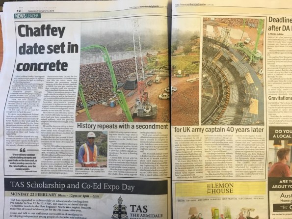
Chaffey Dam Media Article
RE Wall Upstream Walkway and Piezometer Installation; A simple task…
The Reinforced Earth Wall (7.2 x 6.2 x 500m) that is currently being installed on top of the existing Earth & Rock-fill Dam also requires a small walkway on the upstream face. This is required to allow for the inspection of the settlement points as well for monitoring the RE wall itself (panel verticality/movement and for extracting the internal galvanised test straps).

DESIGN
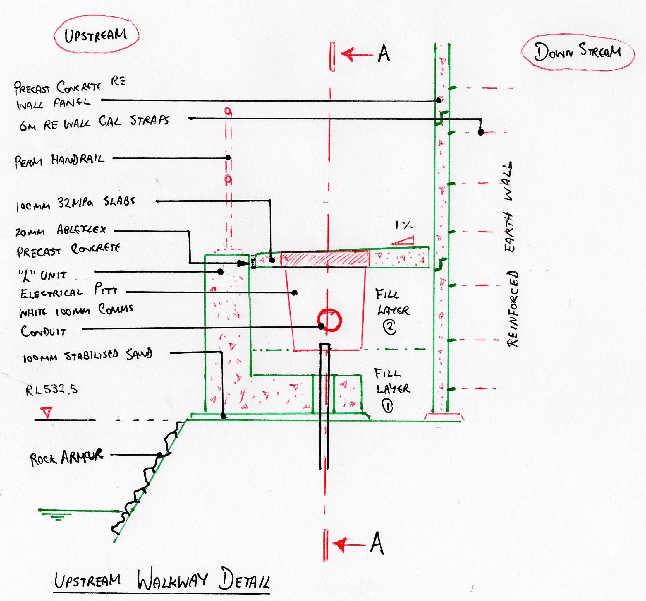
EPSON MFP image

METHOD
- Placement of stabilised sand (100mm). This was simply to provide a firm level surface for the L-Units to be placed upon as the large, angular 4B material produced an inconsistent surface level. It also allowed the temporary handrail to be secured in placed.
- Installation of temporary fall prevention system/ handrail.
- Backfill of rock armour on upstream face. Required to cover the stab-sand and improve aesthetics (..and durability)
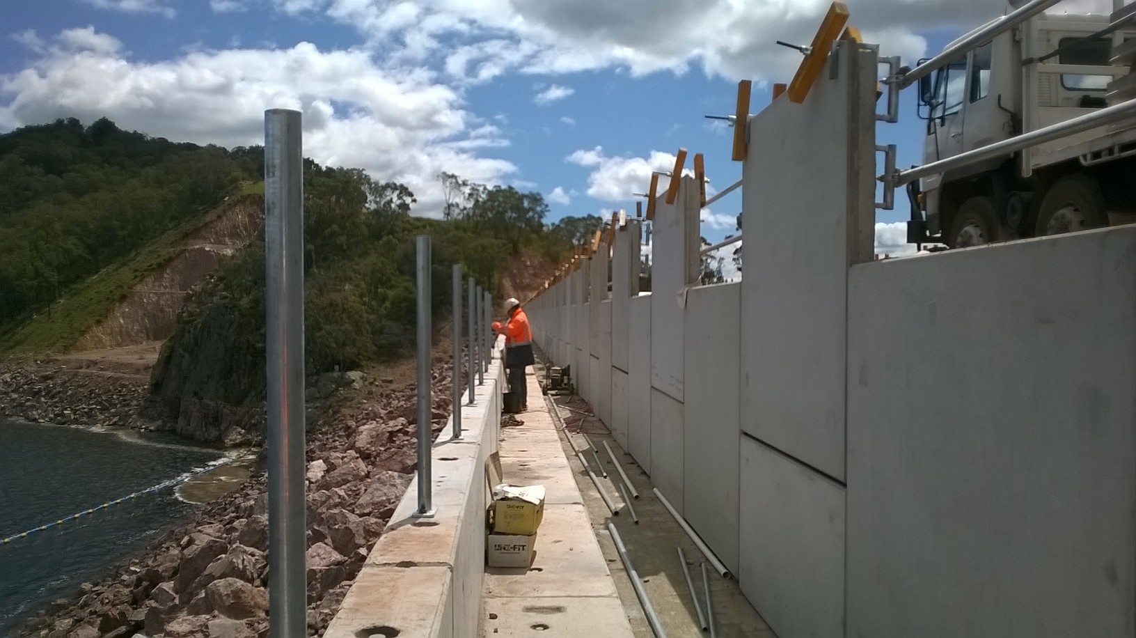
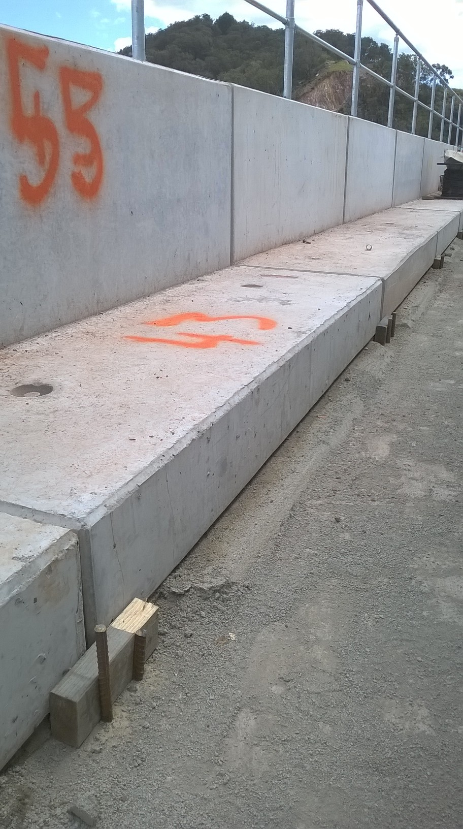
- Installation of precast L-Units. (see photo 1). Originally, designed to be gabion baskets, these precast units were favoured for aesthetic reasons. The finish and uniformity of the units was flagged as being very low.
- Removal of temporary fall prevention system. (Design of fall restraint anchor required- see below)
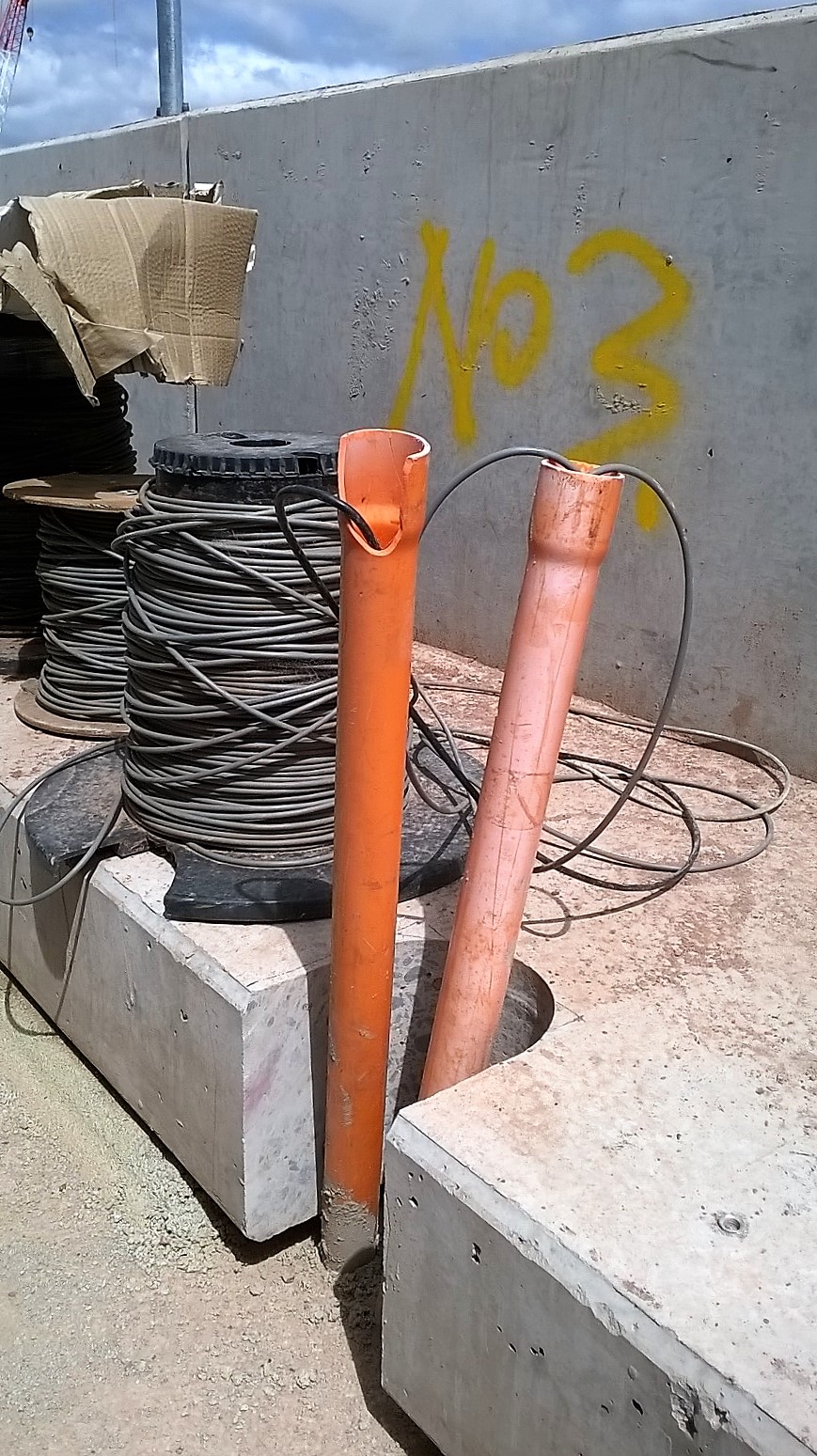
- Core drilling of L-Units to allow piezometer conduit to pass.
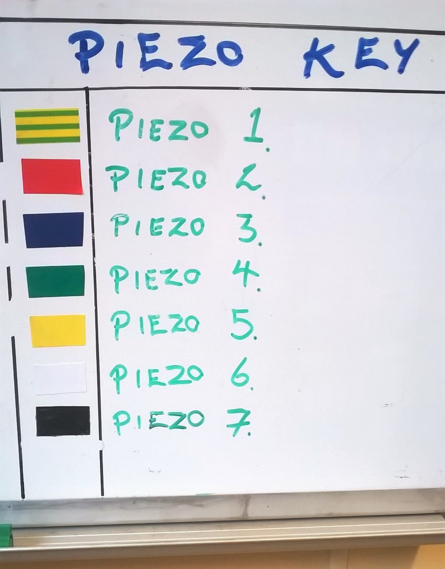
- Piezometer marking/ protection.
- Installation of permanent handrail to top of L-Units.
- Backfill of precast concrete L-Units using large rock-fill material (Layer 1 (0.45m)). Agreed upon by SPE due to large cobble aggregate to be used (20 – 75mm).
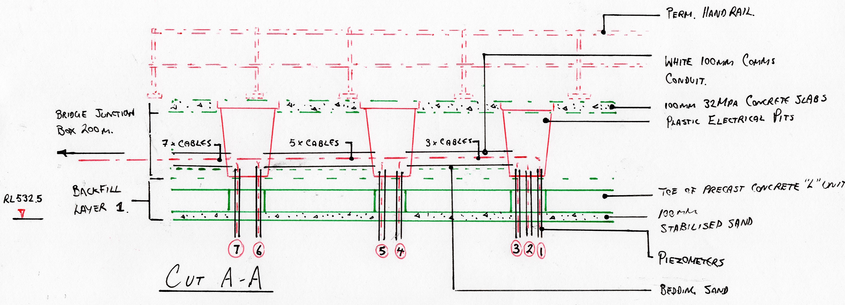
- Installation of plastic electrical pits.
- Further placement and compaction of backfill material (Layer 2 (0.45m)).
- Installation of pavement formwork, steel reinforcement, jointing, end stops.
- Construction of concrete pavement (310 x 1.6 x 0.1m).
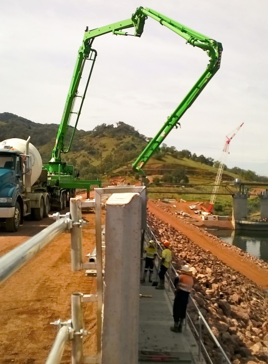
Point Loading the RE Wall. I assessed that the pumping of concrete from an unfinished RE Wall to a walkway 3m below was the greatest risk to this phase of construction. A 36m pump would be positioned onto the RE Wall crest in order to pump 12 x 6m slabs/ day. Each outrigger leg was rated up to 192 kN but with the walkway so close, it was assessed that this force was unlikely to be approached. Upon receiving the concrete pump technical data, it at first appeared as though we would not have sufficient space (See image below). Fortunately, this was not the case and it was able to safely operate simply using an alternative outrigger configuration. The important dimension was that of the 1.5m exclusion zone from the internal face of the RE Wall within which the outrigger could not encroach. This was likely due to the lack of frictional resistance offered by the steel strapping at such proximity to the RE Wall Face which prevents the vertical panels from pushing out.
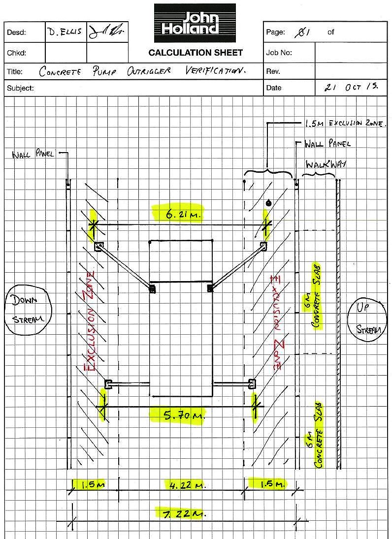
Outrigger dimensions breach RE Wall exclusion zone
Working at Height. Due to the steep upstream face, a temporary handrail was installed to provide a fall prevention system. Once the L-Units were in place the temporary handrail was to be removed. However, workers were required to wear harnesses for the removal of the handrail as it required them to step on the outside of the L-Units.

Due to the lack of fixing points, I was required to design a fall restraint system. M16 5.8 bolt was used with a small steel plate to provide an anchor point for harnesses. The simple anchor design required external verification before it could be signed off. A couple of hours later and the design was approved for immediate use.
Securing the L-Units. As part of the RECO L-Unit system, hot dip gal sheer keys are provided which meaure 1m in length. These slot vertically in between each concrete unit and ensure that the individual units operate as a continuous structure, whilst allowing a certain degree of movement. However, due to the subsequent placement and compaction of the cobble fill material between the RE Wall and the L-Units, I decided to pin them in place using 4 x steel rods as shown below. This was to prevent the units moving laterally away from the RE Wall as compaction occurred.

ISSUES
Piezometer Alignment. When initially setting out for the installation of the walkway, it soon became apparent that the piezometer alignment would conflict with the position of the precast concrete L-Units. Consequently, 100mm holes had to be drilled through the precast units to allow the piezometer conduit to pass through. As JH were also responsible for the location at which the piezometers rose vertically during prior groundworks (and before my arrival!) it was a simple matter that could have been avoided.
Missing Materials. Despite being fully assured by my predecessor that all components were correct and present I was a little under the moon to find out that approx. 10m of handrail fixings were not accounted for but an additional 30 vertical post were present… A swift call to the manufacturer and all was well.
LESSONS LEARNT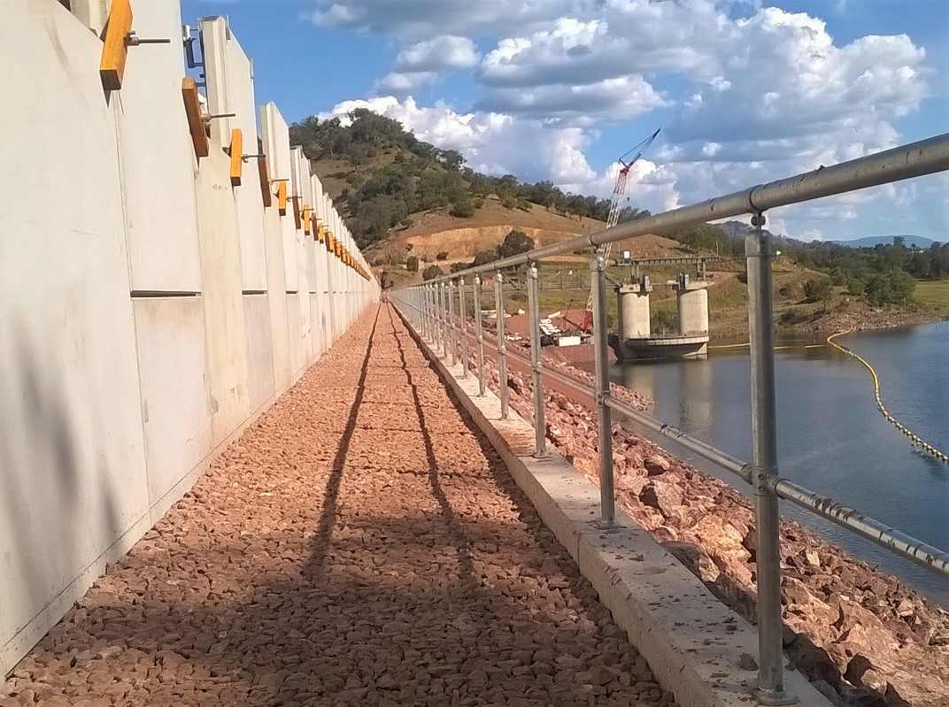
5 x P’s!! – Poor planning lead to several avoidable issues during construction. ie. Precast L-Units requiring core drilling (5 x 100mm Ø holes) to allow for the Piezometers to pass up vertically to the surface of the walkway.
Precast Unit QA – Do not rely on consistent geometry of precast unit in planning.
Each of the precast L-Units has 2 x preinstalled ferrules. These provided a metric thread fixing point in precast concrete panels to which the permanent handrail will be installed. Due to the lack of conformity in the geometry of the precast units, the horizontal alignment of all the ferrules once all of the L-units was far from straight (even by Aussy standards). The final handrail would have looked terrible. As such the decision was made to drill and install new ferrules in order to achieve an aesthetically pleasing handrail alignment. See final alignment above.
Check and Double Check material quantities!!
Reo Bar Chairs – Ordered 1000 x 45mm plastic bar chairs to sit on the uneven 4B material. Thought to be too many but required more 75% way through bay construction. Underestimated spacing required due to uneven 4B material…
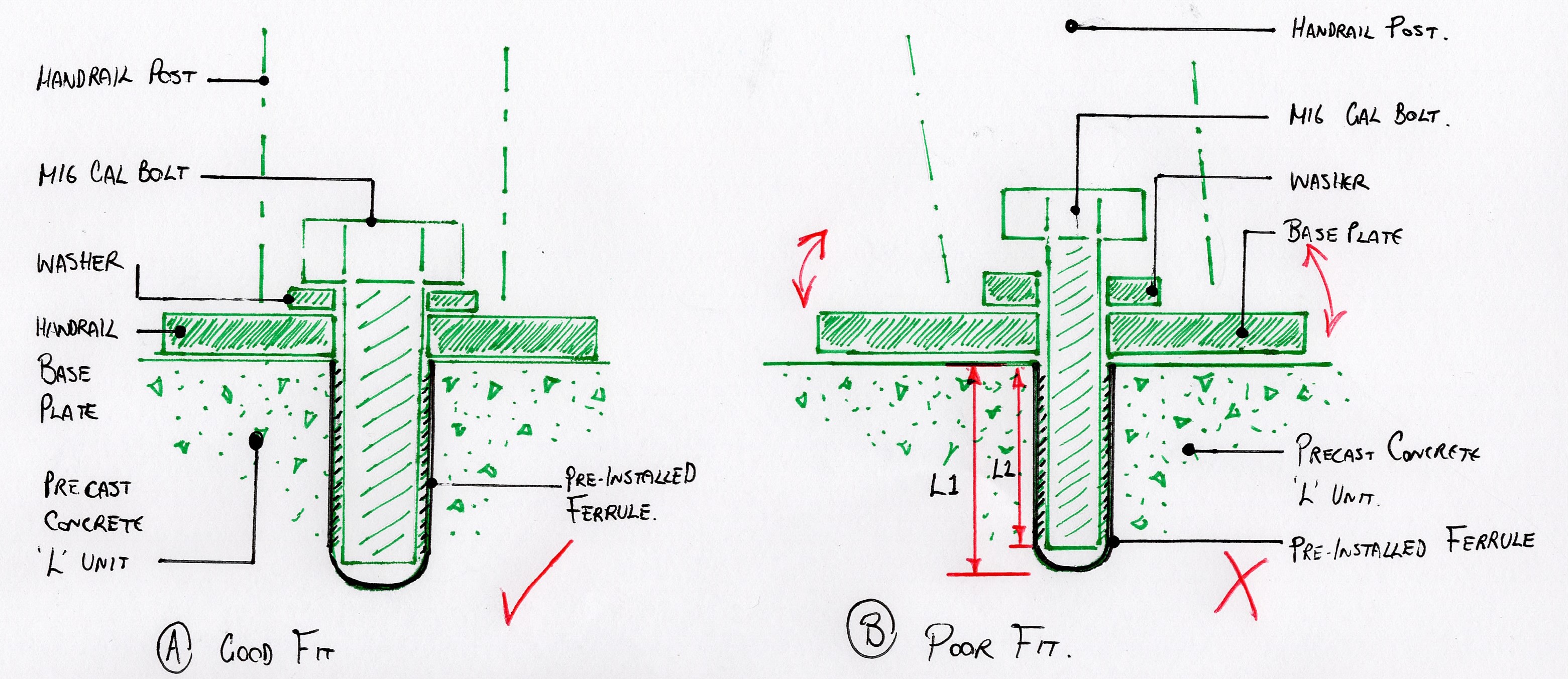
Bolts and Ferrules. To determine the bolt length that was required for a pre-installed ferrule which is not detailed on the drawings, do not simply measure the ferrule depth using a steel rod (who would do that?..). As the base of the ferrule is rounded, the depth that a bolt can actually penetrate is approx. 5-10mm less than the full ferrule depth. If a bolt then protrudes greater than required the handrail baseplate will be loose (apparently..).
EPSON MFP image
OTHER NEWS..
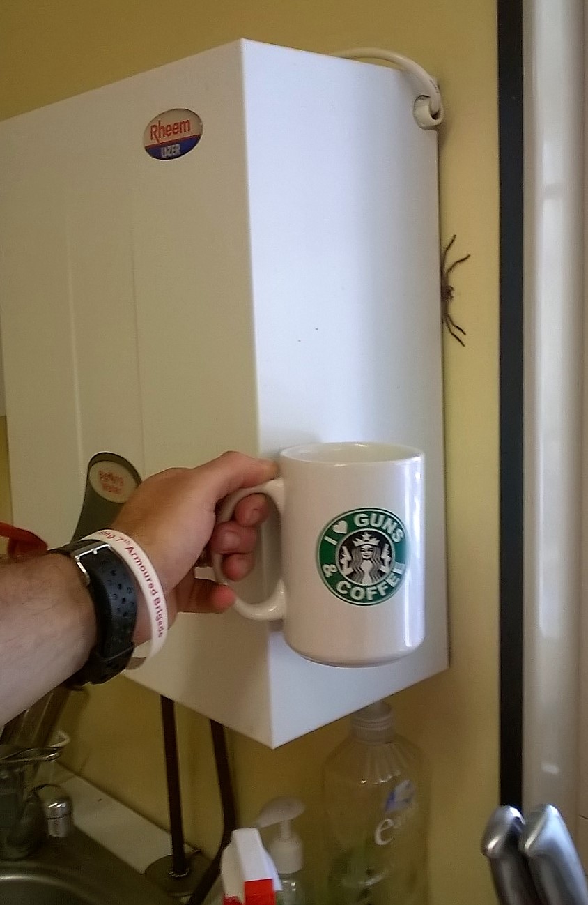
New Chaffey Dam Site Office resident fancies a brew!
A Quarry Conundrum..
1. Project Update. In order to raise the Earth and Rock-filled Embankment dam here at Chaffey Reservoir, a reinforced earth wall (RE Wall) is currently being installed along the existing crest of the original dam (broadly speaking). As the engineer responsible for raising the dam crest, the RE Wall installation falls firmly within my remit. The works have been subcontracted to Fusion Civil Pty, an established earthworks company specialising in such structures. However, aside from the considerable size (500m x 7.5m x7.22m), it is the fact that the earth core is composed of three very differently graded aggregates, vertically aligned into three specific zones that makes this particular RE Wall quite unusual. Such a design has been adopted in order to control the rate of seepage whist preventing any water being visible on the downstream face. The zoned fill technique has also been adopted within the existing embankment dam below, however this also has rock armour installed on both the upstream and downstream external gradients. The primary impact of having zoned fill material within the RE Wall is the slower rate of construction; a fact that Fusion Civil are currently discovering to their cost (quite literally).
Chaffey Dam & RE Wall Upstream Face
2. Quarry. As well as being the engineer responsible for raising Chaffey Dam I also manage the on-site quarry which includes the sourcing, screening and crushing, load/ haul and all associated QA. A great benefit of the location here at Chaffey Reservoir is the local geology, perfectly lending itself to an on-site quarry for the both RE Wall Fill and road base material. Whilst it may sound to be a fulfilling and interesting role, the quarry has been the source of great frustration and angst since day one. Primarily, this is due the ‘cheggars’ subcontractor that John Holland selected to conduct all crushing and screening of the raw material. More to follow…
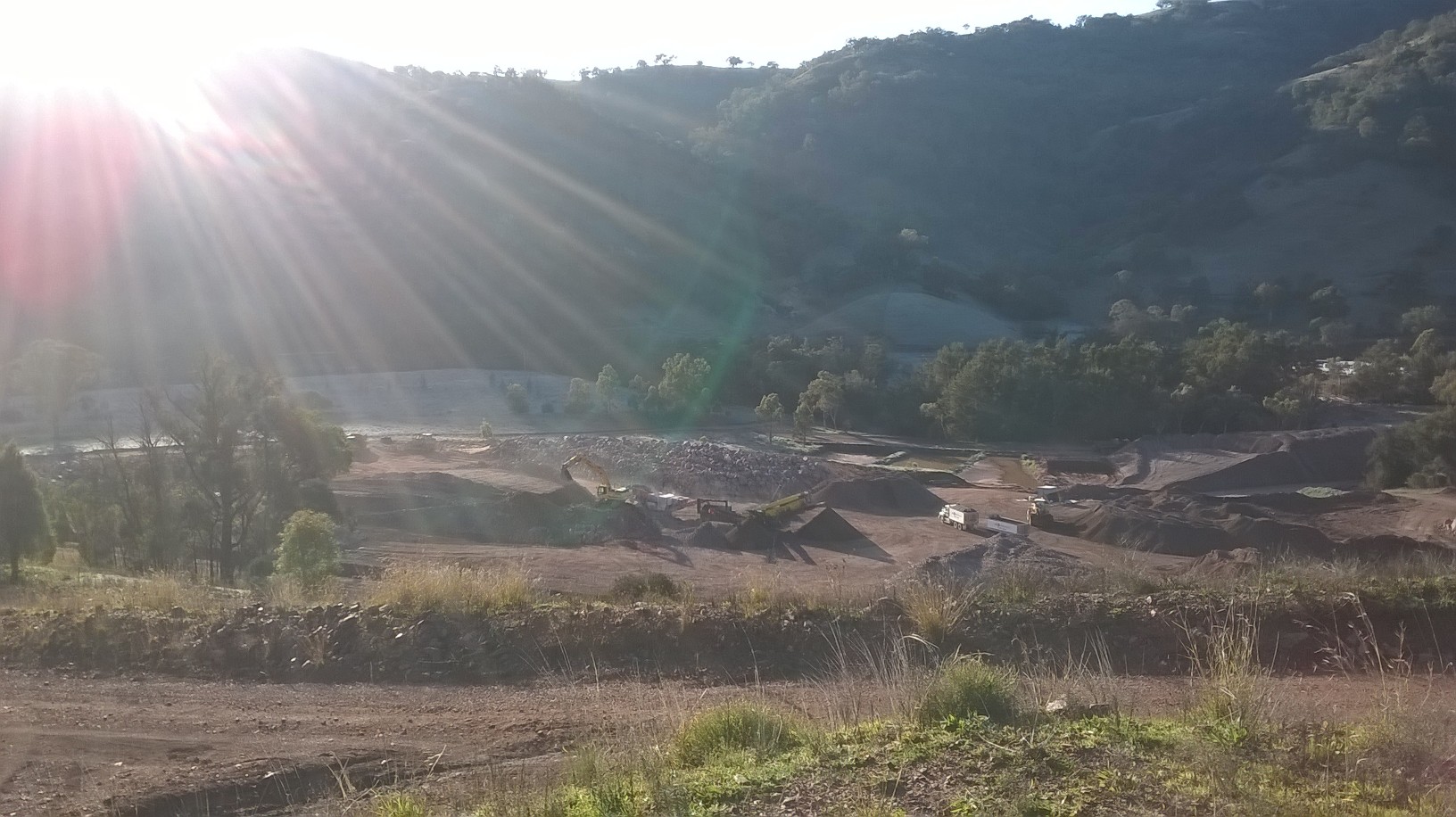
Chaffey Dam On-site Quarry
3. At present the RE Wall has had six 0.3m layers of fill and three staggered layers of 2m high precast concrete wall panels. Each 0.3m layer of fill material is hauled up to the crest from the quarry (≈1.1km), placed by a single CAT 730 articulated dump truck (due to with restrictions) before being spread and finally compacted by Fusion Civil. Once 50% of a layer has been placed and compacted I request that compaction is checked. A local Geotechnical firm provided the material technician who then determines the densities of the in-situ material using a nuclear densitometer. For QA purposes I chose to divide each layer of fill (≈ 950m3 aggregate) into two work lots (chainages 0-250m and 250 – 481m) based upon work lot sizing guidance within Australian standards (Roads & Maritime Services Q6). Finally the layer is strapped with the reinforcing galvanised steel straps as shown in Fig 2. Remarkably, it is the steel strapping that provides the structural integrity of the RE Wall. The straps provide the tensile strength that holds the precast concrete panels in position simply from the vertical load imposed by the compacted earth layers.
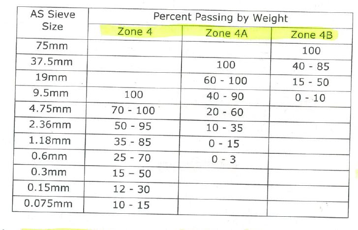
4. Volcanic Resources Pty are the subcontractor who are responsible for all crushing and screening of raw materials. Their primary function is to produce the correctly graded material as specified within the principle contract (CDASU GC21). The three materials are categorised as zone 4, 4a and 4b and increase in aggregate size respectively. Zone 4 material is the initial material located in the zone closest to the upstream internal face of the RE Wall in a 2m wide strip running the length of the wall. It has the lowest permeability of the three fill materials and is a reddish/ brown, well graded, angular, silty SAND. Zone 4a is the next material located in the centre 2m strip of the RE Wall. It is also reddish brown in colour and well graded but is a sandy GRAVEL that is designed to allow water through at a greater rate whilst providing structural integrity within the earth core. Finally, is the zone 4B material. It is placed in a 3.2m wide strip between the centre and downstream internal face of the RE Wall. It is a grey, poorly graded, angular, gravelly COBBLE that is designed to be highly permeable whilst providing structural integrity. Due to the high voids ratio water is able to pass freely and is a requirement as it is intended to prevent water ever reaching the very large rock armour on the downstream face of the Embankment dam. The idea being that if the public were ever to see signs of water penetration on the downstream face of the dam, panic would ensue.
5. Material Conformance. The latest issue has been one of material conformance. Until recently, Volcanic Resources produced all fill material simply using an industrial rock crusher and a mechanical screen. The machinery was set up to produce all three required products concurrently
( 4, 4a and 4B.) However, approximately five weeks ago the large zone 4B material was no longer required as I determined that the stockpiled volumes met the estimated demands for the remainder of the project. Despite this, the 4B material continued to be produced as an unwanted bi-product at a considerable rate. At this time, half way through the project, the subcontractor demanded that material prices were renegotiated due to the sudden reduction in his earnings. JH politely refused yet were unsurprised by the request due to previous grievances raised by the subcontractor. The subcontractor subsequently request that JH purchased a cone crusher, in addition to their own crushing machine. The idea was sold to JH under the guise that all the oversize waste material could then be re-processed, saving JH the need to excavate and haul further raw material. An agreement was reached whereby by JH agreed to hire a cone crusher up to a limit of $45 K (AUD) after which time Volcanic Resources would assume the financial hire costs of the machine.
So What?
7. Upon receiving the shiny cone crusher, material production rocketed and waste material stockpiles quickly diminished; a relief for me as the zone 4 stockpile was shrinking faster that it was being replenished. However, all was not well. Upon inspecting the material produced, it was apparent that there were distinct differences between the “pre” and “post” cone crusher zone 4 and 4A materials. The zone 4 material appeared overly coarse and failed to bind when moulded. Equally, the previously well graded zone 4A material was now very clean, uniformly graded gravel (perfect for a drive way NOT an RE Wall..). I immediately interrogated the Volcanic production staff on how they verified that they were producing conforming material (As the owner had already reassured me all was well). They simply said there were given a maximum aggregate size for each material and that was it…
8. 48 Hours later and the results confirmed the my concerns. Overly coarse zone 4 material and a uniform 4A material lacking sufficient fines to meet conformance. Fortunately the material had not entered the wall. Unfortunately, the material had contaminated existing stockpiles (but was fairly straight forward to identify and separate).
Lessons Learnt.
9. Do not trust a subcontractors’ word without checking, even if they are contractually obliged to make the product. Do not assume the obvious has been done; Common sense would say that as a material production specialist (i.e Volcanic Resources), if you change anything in a system you would re-test the new material to check for conformance. Clearly this was not done and they simply did not care. When I confronted the owner of Volcanic on the issue I was met with the following response:
“If you want your material to pass, why not test a stockpile that you know will pass?”….

Fill Material Production
10. Since this time, they have struggled to produce conforming material. The cone crusher failed to deliver what was promised and despite clear direction, they have attempted to load failing belt material directly in supply of the RE Wall. Much of my time is now spent in the quarry..
Solution.
11. I directed that we reverted to using predominantly raw feed (high % fines) with a blend of the oversize waste product. Whilst better, the material was still struggling to pass due to a lack of fines. As the ambient temperature has recently risen considerably, I directed that the raw feed stockpile was saturated in an attempt to bind the fines with the larger rock. This had an immediate positive impact and produced conforming material. However, the SPE was not overly happy as JH pay per tonnage and do not wish to pay for hauling water. My dilemma was, do I delay Fusion Civil in the production of the RE Wall due to lack of fill material or pay for the haulage of water?… The saga continues…
Reinforced Earth Wall – Left Abutment
Entering the Morning Glory… but not quite as planned..
MGS Crane Mat on temporary gravity retaining wall.
1. Temporary Works Design (TWD). The decision was made to disregard the original temporary works design for raising the morning glory spillway (MGS) as it was assessed to be unsafe and impractical. As such, a full redesign was required despite the project being two months in. A highly regarded, Sydney based, designer specialling in TWD was approached for assistance in the urgent matter. Upon his acceptance, a “short form consultant services agreement” contract was established. The designer quoted a ten week period in which they would complete the full design. Seven months later and the design remains unfinished.
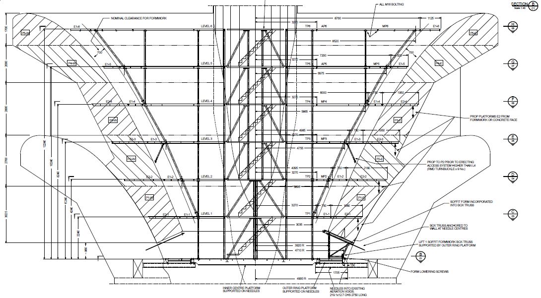
MGS Temporary Works Design
2. Several mitigation measures were implemented in order to account for the significant TWD delays:
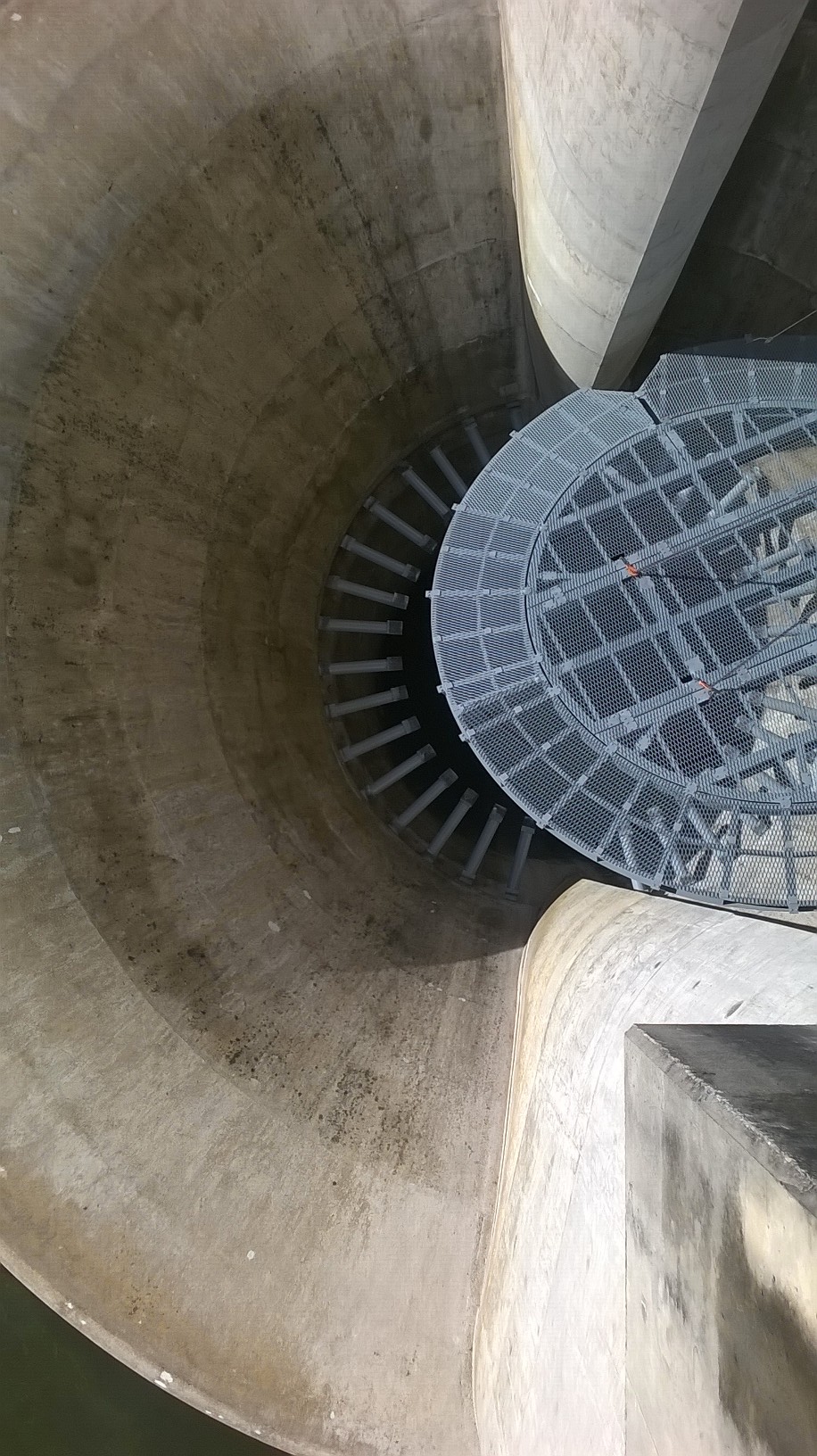
a. Construction sequence. Initially, it was planned that the MGS temporary works access structure was to be fully operational prior to any works commencing within. Due to the TWD delays the decision was made that once the primary supporting system(needle beams and steel mesh base) was in place, scaffolding was to be erected to allow access within. The new method made it possible to beginning locating and marking all existing steel reinforcement prior and the time consuming process of core drilling (1034 holes x 45Ømm x 850mm deep.
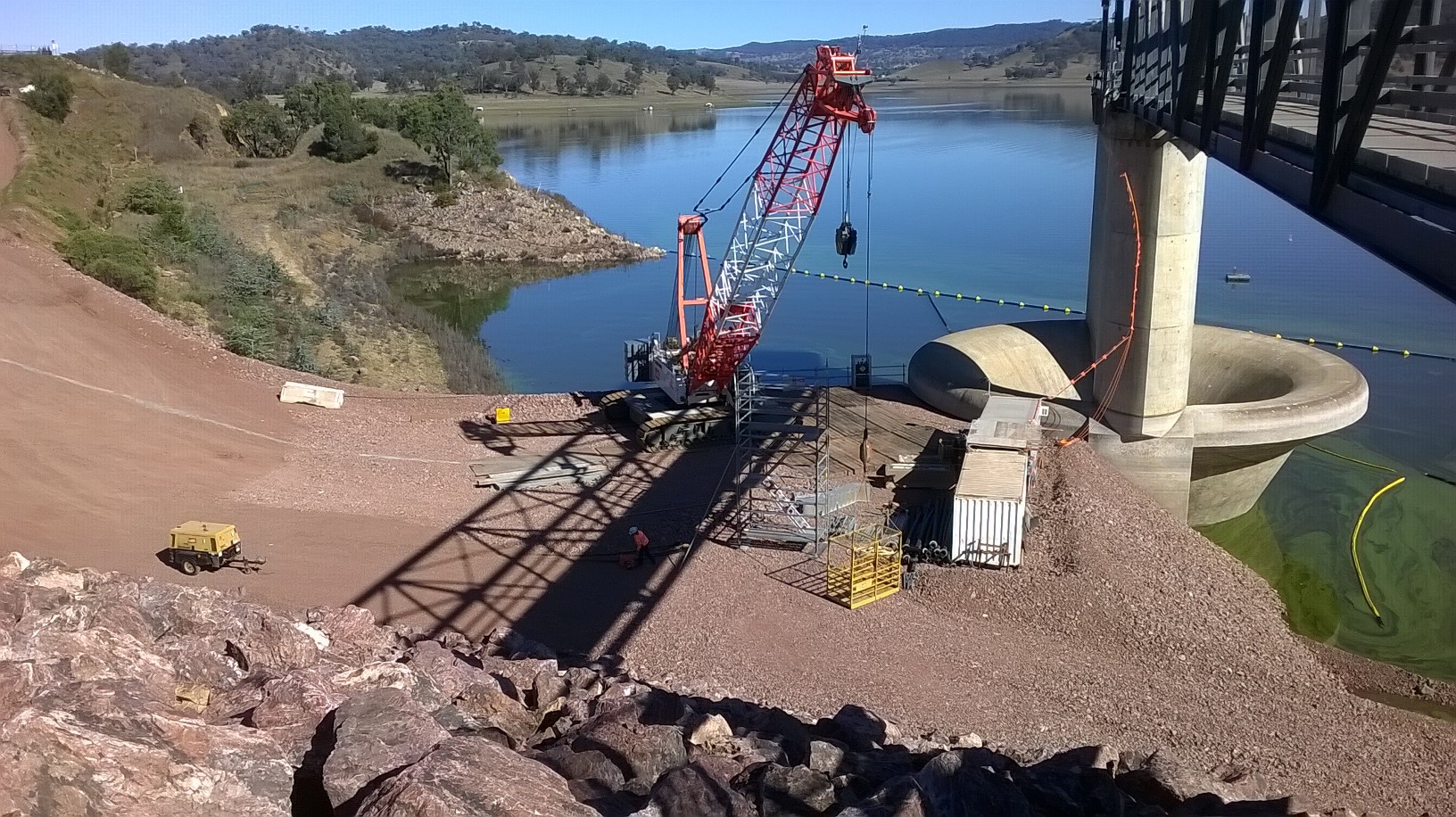
Delicate Lift Operation – 160T Crane inserting the primary, temporary works mesh base onto 34 x steel circular hollow needles within the MGS.
b. Fragmentation of works. In the initial tender it was stated that the MGS temporary access was to be fabricated by a single company. In the interest of time, the decision was made to break down the works into smaller sub works packages that would then be put to tender on an individual basis. Although this measure would facilitate concurrency in production, it would expose the task to compatibility issues in regards to final construction of the temporary works.

c. The remote location of Tamworth also influenced this decision to fragment the temporary works. Local fabrication companies flat refused to makes an offer on the total temporary works access structure due to the required production time. This was because of their limited workforce size, real estate and production facilities.
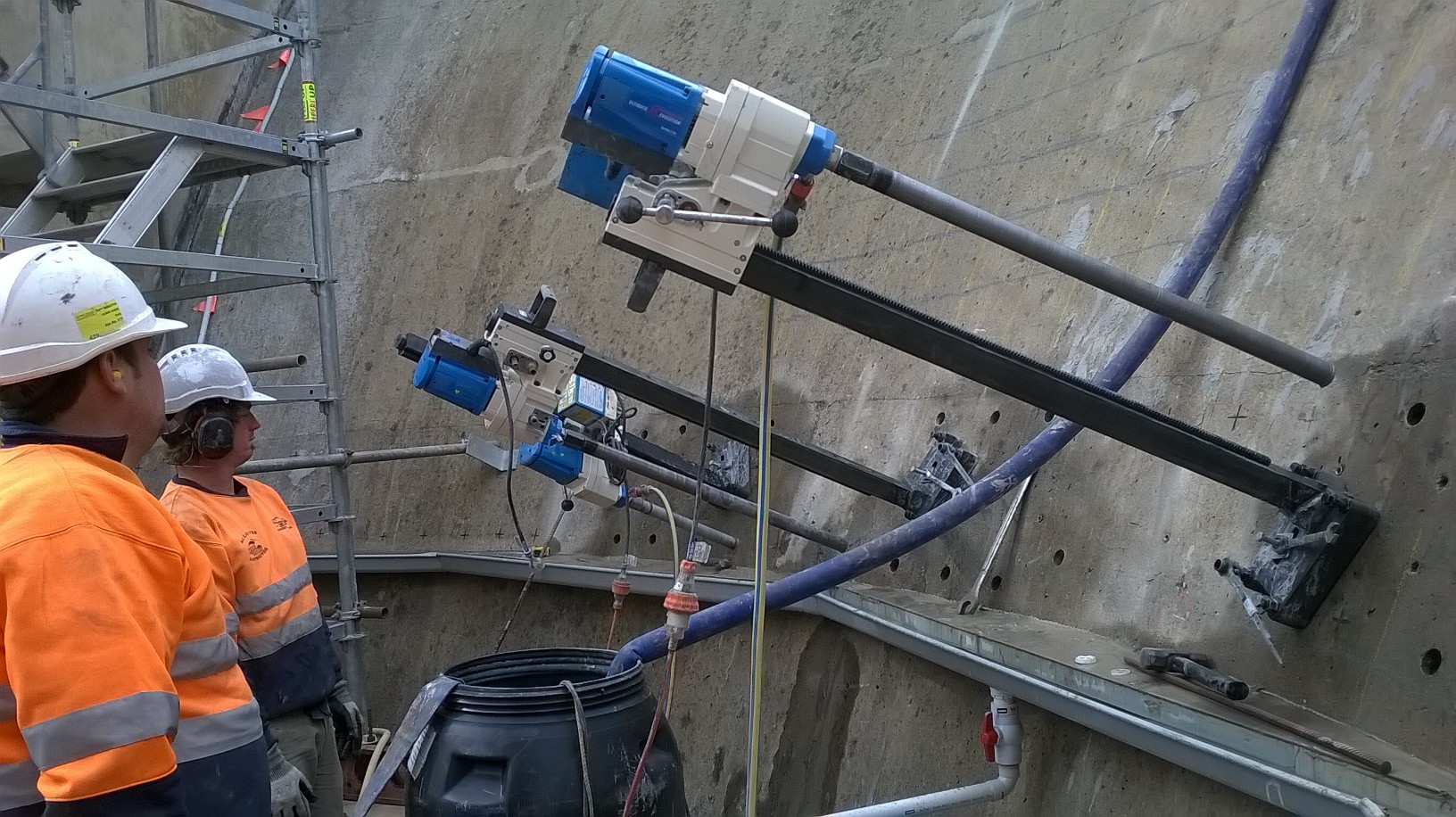
Core Drilling inside the MGS over improvised waste water guttering. Only 1032 x more holes to go…
3. Lessons Learnt.
a. Contract Details. The importance of a thoroughly considered and reviewed contract has been clearly demonstrated in this instance. Although a provisional timeline was provided by the Design Company within the Short Form agreement, it was stated that an extension may be required. Additionally, the Completion Date was strangely specified as “Project Completion”, effectively saying that it’ll be done, when it’s done. Consequently, there is no financial penalty for the designer although they have over-run by five months.
Water Testing in Chaffey Lake
b. Although the upgrade of Chaffey Dam is a State Water Project, funded by public money, John Holland are the private corporation delivering the project. As such, the federal requirement to go to tender on all on sub-contracts where public money is being spent, whilst good business practice, does not apply to John Holland. Following further investigation it was found that the design consultant selected is routinely employed by John Holland due to his impeccable track record and subject knowledge, despite the extended timelines!
Lets Get This Ball Rolling – Chaffey Dam; Tamworth, NSW!!
Having now completed two weeks here with John Holland in New South Wales (NSW), I thought it was time I provided a brief synopsis of the Chaffey Dam Augmentation and Upgrade, a little on my transition back to the 1980’s and an insight to Tamworth itself.
CHAFFEY DAM
The project centres on the upgrade of an existing earth & rock-fill dam and accompanying spillway in order to increase the storage capacity of the Chaffey Reservoir from 62GL up to 100GL It is a $40 million (AUS) design & build contract (CG21) at the request of NSW State Water Corporation, a project born from the increasingly desperate water shortages experienced in Tamworth region of NSW and surrounding agricultural communities. Three distinct areas of engineering are immediately apparent within the project:
1. The raising of the earth & rock-fill dam.
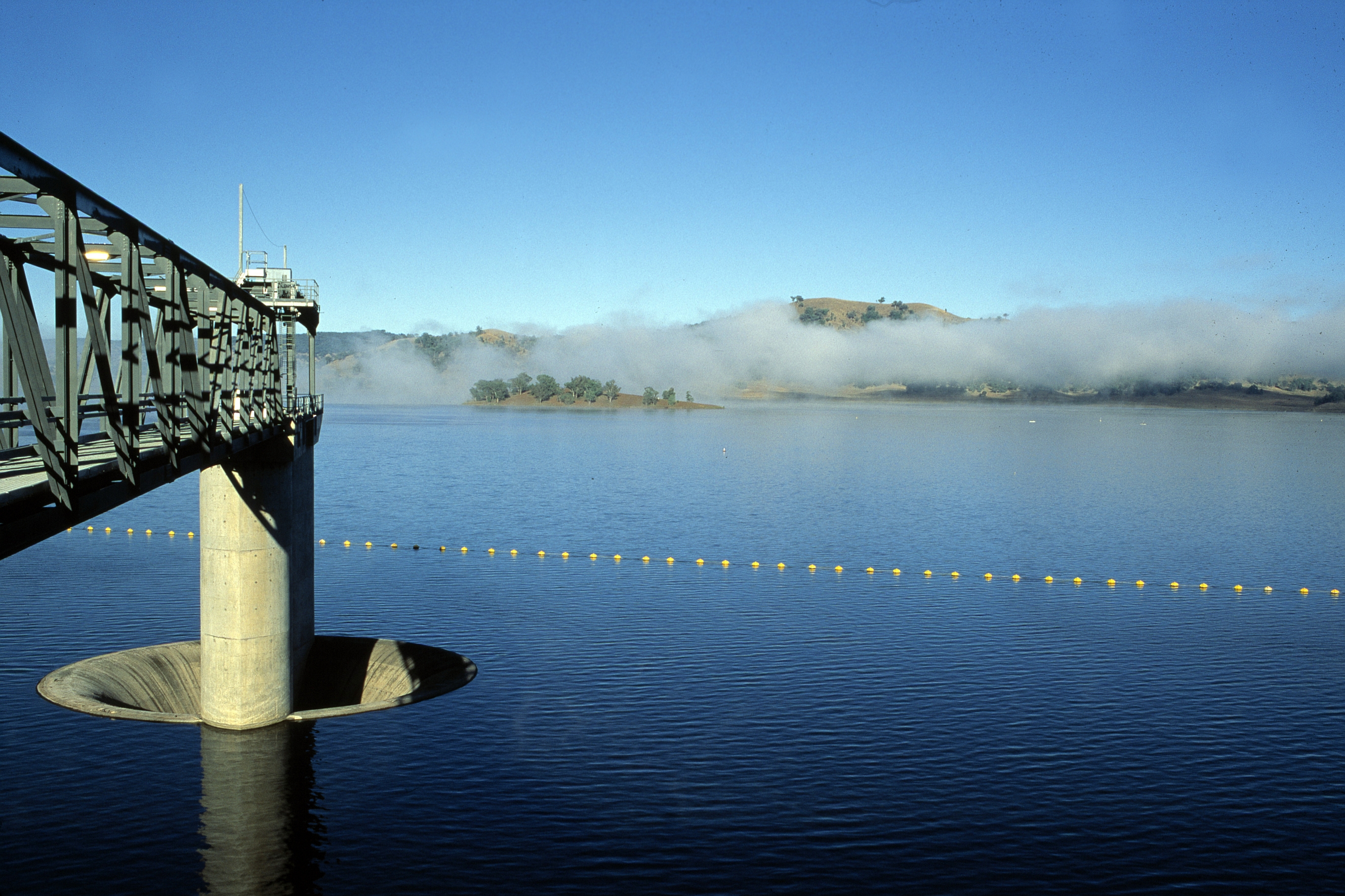
2. Raising the Morning Glory (Pretty dam funny, I thought so too..)
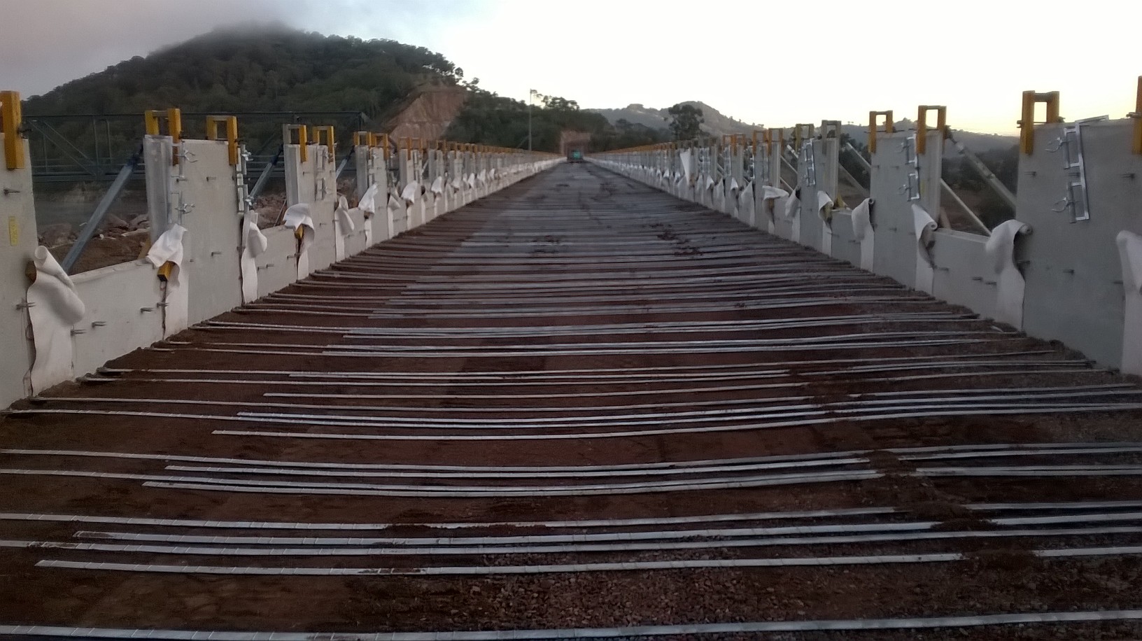
3. Replacement of a simply supported, concrete road bridge.
1. Raising of the Dam. Unfamiliar with earth & rock-fill dams, I found myself bombarding the site engineer and experienced foreman on the workings, benefits and considerations associated with such a structure. Based on a layer system, the structure has a clay core which is to act as impervious membrane. Surrounding the clay core are several thick layers of coarse aggregate, with each layer increasing in aggregate size until large boulders exist on the external face. The purpose of which is two-fold; firstly the surrounding aggregate/boulders are there for durability/ protection/ stability. Secondly, the aggregate layers act as a wick (details of which I’m yet to fully explore), but effectively it serves to remove moisture away from the clay core, whilst preventing the migration of fines.
2. MGS. What sets the dam apart, particularly amongst the dam enthusiast society, is really the fact that there is a “Morning Glory Spillway” (hours of fun right there..) as opposed to a typical broad crested spillway for example. This is effectively an elevated plug hole within the reservoir that once surpassed by the storage water level, allows water to flow at controllable rates beneath the dam and out into the original watercourse, Peel river. Fortunately, this aspect of the project is what I have been requested to focus on. Due to the uniqueness of the structure, the temporary works design has proven to be quite challenging. The double curvature of the formwork, access, installation and maintaining an operational spillway throughout are just some of the considerations I will be exploring further. (I wont attempt to explain without drawings)
3. Bridge and Road Infra Upgrade. As the storage capacity of the reservoir is to be dramatically increased, clearly so too does the potential water level. A consequence of which is that existing roads/bridges in the surrounding area also need to be raised or protected. 5km upstream of the dam is the first, primary crossing; an arterial route that provides a key link road for several rural settlements. The bridge replacement was deemed necessary as even at the original 62GL capacity the bridge road surface would frequently become submerged. The new bridge is to be approximately 9m higher and constructed in a new location. The final span was completed last week and the brushed concrete deck is currently 50% complete. Interestingly, the bridge aspect of the project was “construct” only, yet issues with unforseen ground conditions (v.hard rock) lead to delays (despite numerous historic ground investigations clearly point this out!)
!NON-PET INFO!
Tamworth is a gorgeous, sleepy little country town with an awesome backdrop of green, misty mountains. Eva loves the red parrots flying about in the mornings but is not so keen on the giant bats (unbelievable, huge horror-movie buggers that literally fill the sky) but the decent local animals more than make up for them (Kangeroos/ Koalas/ Emus and talking birds!, . The people are certainly very warm and welcoming but you do sometimes wish you bought the “Anti-Mutant Cream” (as John would say!). Actually, he’d probably fit in quite well around here; they love a good “Rock-Ape”!
Anyway, enough waffle. First impressions are that I am very fortunate to be involved in a such a unique project with so much variety, in a spectacular location as part of an experienced, welcoming and competent project team.
