Archive
When it all goes to SLUMP
G’Day from Melbourne, Australia!


The work is just starting to pick up on my site at the West Gate Tunnel Project (Maribyrnong River Crossing Site) as we prepare to start installing precast concrete piles on land based bridge piers and steel tubular driven piles in the river (due to start over the next 2-3 weeks).
The precast piles are being utilised for foundations across almost the entirety of the WGTP, culminating in thousands of individual piles in total. Although the project has its own precast yard, the procurement of precast piles has been subcontracted to piling specialists ‘Keller’s’, who are manufacturing the piles, delivering them to site and driving them into position.
Today saw the first four piles for my site cast. As part of the quality assurance, the IREA (third party auditor) are required, under the Inspection Test Plan to conduct inspections of the reinforcement and concrete mixture, under a Hold Point, prior to pour. I decided to go along for the day and capture this procedure and provide assurance that checks were being carried out in accordance with the ITP.
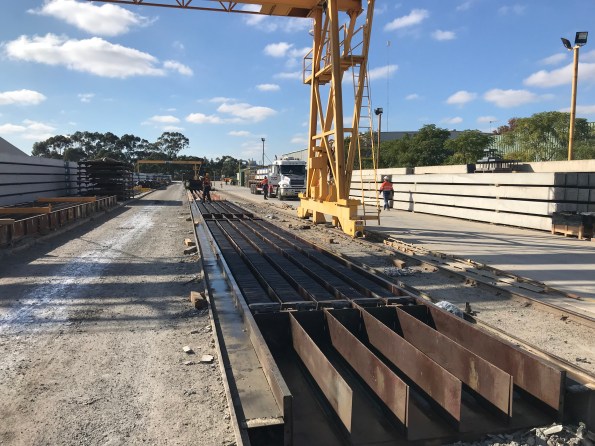
The Casting yard is a rather simple and effective set up, involving runs of four moulds for approximately 100-150m or so. The reinforcement cages are lifted into moulds, onto spacers (to ensure cover requirements are met) and then cast continuously throughout the afternoon from concrete agitators. As mentioned previously, Keller’s are manufacturing thousands of these piles, in various lengths and with several reinforcement details. Meaning a slick manufacturing operation is now in process. A typical day runs as:
- 0600 – strike previous days cast from mould and stack onto dunnage;

- Clean moulds and prepare lengths;
- Install reinforcement cages;

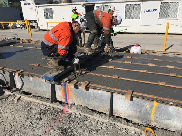
- Conduct QA checks;
- Cast moulds (checking concrete mixture through slump and cubes samples)
The piles are stored in the yard for 7 days, at which point they are transported to site, where they must continue to cure for a further 7 days prior to driving; this allows adequate time for compressive strength of the concrete to be achieved (60MPa in this case).
Today, I got the chance to witness the importance of slump testing. The slump test for the concrete mixture had a range of 160mm-240mm slump. The second mixer to arrive on site was tested on arrival (as are they all) by a subcontracted specialist (Construction Sciences), and a slump of 110mm was measured. This resulted in the concrete batch initially being refused; not great considering half the pile lengths were cast and continuous pouring was required. As the slump water/cement ratio was too low, a simple solution was possible, add more water!

Clearly the question to be asked was, ‘how much water?’. Of interest was to see the difference in approach between the engineers and concreters on site. The engineers, as you’d expect, started conducting calculations to estimate the volume of water needed to reach the required slump. The concreters decided to go with the more traditional ‘this is what we did before, that looks right’ approach, as if from nowhere, to which they tried to argue was correct; clearly the calculated route was taken forward …. and proved correct.
From this experience, I learnt the importance of simple and quick testing on site and the need to take a calculated and measured approach to problem solving as it appears the ‘guys’ on site will just crack out the ‘this is what we did before’ line; something that you seem to hear a lot.
I’ll be sure to put some stuff up once the piling starts, especially the marine piles and the dynamic testing involved.
Steel Pile Fabrication
G’day from Sunny Melbourne! this blog will be much shorter than my last!
I’m sure all the Phase 2 guys remember our trip to NU Steel back on Phase 1 prior to Ex STEEL (that might seem like a life time ago already for some!), where John provided us with the opportunity to see the steel fabrication of gantry elements etc.
I thought I’d just share some photos of the fabrication process being undertaken by ABFI Steel Group (specialists in the fabrication of large diameter steel and pipes – https://abfisteel.com.au/), the specialist subcontractors that have been contracted to fabricate and deliver the steel tubular piles being installed for marine based pier foundations in the Maribyrnong River, Melbourne.

Typical marine Pier Section
The steel piles being installed in the river are 36mm thick, 2.2m in diameter (in the largest cases) and are being driven up to 35m RL. They have been designed to a maximum axial compression load of 28.6MN each. This poses a serious logistical challenge for delivery to site, considering the piles are being manufactured in Wacol, Queensland (only a 1021 mile drive – or 17.5 hours … in a car … ) and will be delivered by road. Clearly at 35m in length, the piles will require splicing on site, with sections being fabricated at roughly 16m sections. This will increase the number of deliveries, and of cause, creates issues with managing quality of splicing on site (a process that is being reviewed, in detail, as I write this). I will be involved in the Inspection Testing Plan (ITP) for these splices and will be required to ensure QA processes are conducted in accordance with the ITP.
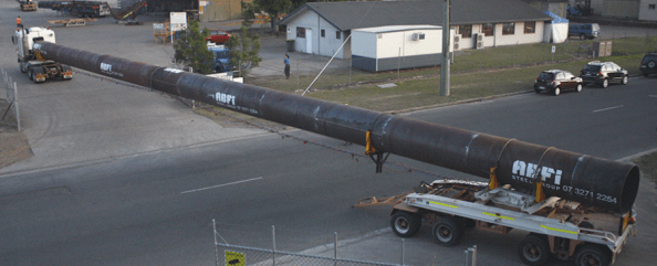
Example of a Steel pipe Delivery by ABFI.
Below are pictures from the fabricator’s workshop of piles being fabricated (unfortunately, at over 1000 miles away, I was not able to pop over and get the pictures myself). As can be seen, some serious work is being conducted in this fabrication process as tolerances/quality are tight. This has led to some serious interrogation of the subcontractors method of works and QA system to ensure the piles are competent once manufactured.
I look forward to seeing the piles arrive on site and being installed as part of a complex method involving two marine barges to facilitate lifting and driving of the piles in the river.


Arrival on the West Gate Tunnel Project
Having completed Phase 1 of the PET(C) I have successfully transitioned onto Phase 2, working for John Holland on the West Gate Tunnel Project (WGTP) in Melbourne Australia (a fantastic city with great weather, so far). I have now been in the site office for 2 weeks and think I have enough of an understanding of the broader project and my site to impart some of my findings and thoughts on this blog.
I apologise in advance for the length of the blog, but I think this is testament to the sheer scale of works involved!
West Gate Tunnel Project Overview
The Clients have formed a partnership between the Victorian State Government and Transurban, and have selected two contractors to deliver the A$6.7 billion (approx. £3.65billion) infrastructure project. These are CPB Contractors and John Holland (CPBJH JV) in a 50:50 joint venture. Major construction work started in early 2018 with the project scheduled to open to traffic in 2022.
The project aims to deliver an alternative to the West Gate Bridge to the West of Melbourne’s city centre, close to the Central Business District, which currently caters for more than 200,000 vehicles a day, a very busy and congested route; having used this route for 2 weeks, in rush hour, I can certainly vouch for this.
The project involves building four more lanes on the West Gate Freeway, twin underground tunnels, a new bridge over the Maribyrnong River that links to an elevated road and a 14km Shared User Path (SUP). These three key areas have been split into three zones of interest; West, Tunnel and East.
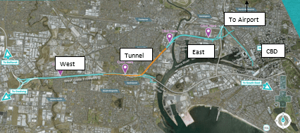
Breakdown of WGTP Zones
West Zone: Construction of four additional lanes the West Gate Freeway.
Tunnel Zone – Construction of twin tunnels running north to south, linking the M1 west of the West Gate Bridge to the North of the CBD. These tunnels are 2.8km and 4km.
East Zone –This zone will see the construction of three bridges (one freeway and two joining slip roads) across the Maribyrnong River and an elevated freeway linking into the centre of the city. This is where I have been positioned.
East Zone
Testament to the sheer size of the project, the East Zone has been split into five subzones outlined below (remembering that this is one of three). I have been placed in subzone 401 (or the ‘Maribyrnong River Crossing and Mackenzie Road’ subzone’), which will see the construction of a four-lane bridge across the Maribyrnong River with two adjacent on/off ramps (both bridges in their own rights), a connecting bridge on the east bank between both slip roads and a raised SUP (approx. 5km of the total 14km being built).


My Role
My official role within the project is as a Project Engineer working in the substructures team, of which my duties include: Planning of works, ensuring compliance with quality and procedures, monitoring safety and environmental controls and provide technical assistance to the Foreman and workforce. The task of the substructures team is to install all foundations, temporary works for the superstructure team and install all structures up to the point that the bridge decks can be installed (i.e. installation of bridge piers up to the bearings).

Example of Substructure Team’s Limit of Responsibility
Initial Thoughts and Risks
Driven preformed and bored cast-in-place piles are to be used for the foundations of the bridge, including 400mm square precast concrete piles for the sections of bridge located out of the Maribyrnong River, and steel tubular piles with reinforced concrete infill, to approx. half the depth of the pile (I believe this is for durability reasons over structural, i.e. susceptibility to corrosion of the steel tubes in the upper formations, but I hope to clarify this soon. This does make me think that there must be a method of transferring load from the RC to the steel tube at the point of RC stopping; I’m assuming through friction?), for the piers supporting the river crossing spans. Bored cast in place piles will be used for the SUP.


There have been many boreholes drilled along the alignments of each bridge as part of the GI, suggesting to me that CPBJH JV have considered ground conditions to be a key risk in the execution of these works. The GI appears to be comprehensive. Comparing the alignments, I could see that the ground changes dramatically on the East bank of the river between the three bridges. This rang alarms bells in my mind as the steel piles were clearly designed with the toe formation in the Lower Older Volcanics to achieve the required end bearing capacity. To understand how they plan to mitigate against the risk of the ground model being incorrect and the pile toe not reaching the required formation boundary, I consulted the geotechnical engineers subcontracted to design the piles who informed me that they have designed the piles 2m longer than the expected required depth for such a scenario.

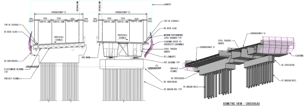
Typical ‘In River Pier’ Piled Foundation


The precast piles, which are working as pile groups, are designed across the site with a toe depth that reaches formation in the Upper Volcanics formation. Again, there is clearly a risk here that these piles may not reach the required depth, based on the varying formation levels in the ground. It appears that the risk has been mitigated here by relying on the high number of boreholes conducted. I shall see how this manifests as the piling starts.
Typical ‘In Land Pier’ Precast Piled Foundation
From what I can understand, the leading factor for using driven piles across the whole project (not just 401) is the ability to limit soil excavation and disposal. When I first arrived at the area I could see vast piles of covered soil from previous excavation works. Intrigued by the reasoning for this I consulted the East Zone Manager, Alan Platt, who informed me that the soil across the whole site had been found to be contaminated and required specialist removal from site at a cost of approximately A$500 (if I remember correctly) per m³. This had not been picked up prior to the contract being agreed between the Client and CPBJH JV, with CPBJH JV unwilling to pay for the thousands of cubic metres required to be removed (clearly this would eat well into their profit margin). As it stands, from my understanding, the Client and CPBJH JV are working to find a solution to this through negotiation. I plan to dig (ignore the pun!) further into this to understand where the risk for such an event was held and how it could be avoided in the future.
In total, 738 piles are required for the permanent works alone. This does not consider for the temporary works piling, of which there is a lot; for example, 70 are required for temporary jetties alone (a whole other topic that I will look to discuss separately).
Looking at the bigger picture, it is estimated that more than 5000 piles are required for the WGTP. This led to the setup of a precast yard (something I plan on visiting soon), which will produce precast piles, bridge decks, super T’s and other precast elements. From the immense numbers of precast elements required, along with the relatively short timescale of roads opening in 2022 (not a single pile has yet been installed in the East Zone), I see procurement of precast elements as a key risk for the project and must be managed closely; piles require 14 days curing prior to delivery. It is my understanding that precast elements have not been poured for 401 yet, which makes me question our ability to begin piling precast piles on time; a quick bit of simple maths (i.e. counting days) makes this apparent. We shall see!
Summary
I have arrived on site just as site clearance and preparation has started. This has provided me with the much-needed time to understand the ‘bigger picture’ of the WGTP and the intricacies of my site (and get my head back into John Moran’s Lecture Notes!). Over the next couple of weeks, I intend on interrogating the contract in more detail to understand what is driving the project as well as how my site relates to the WGTP critical path. I look forward to ‘getting my boots dirty’ on site once the piling starts and to the challenges the lay ahead, of which I’m sure there will be plenty.
