Archive
Temporary Works
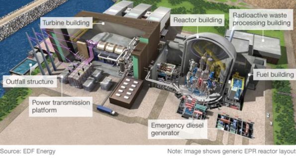
I am working in a team of 10 for the JV that has the main civils contract for Hinkley Point C. Bouygues-Laing O’Rourke (Bylor) are responsible for the structure(s) that contain the nuclear gubbins for the 3200 MWe reactors, cooling systems, and ancillary buildings. Currently circa. £2bn of contracted scope, and rising.
The TW office responds to requests for scaffold, formwork, lifting calculations and other curios from site on an ad-hoc basis. They liaise in advance with the pre-construction team (working mostly out of Paris) to design formwork and falsework systems along with bases for the 40-50 tower cranes to be installed. Large volume packages are let and managed by the TW team to supply chain companies like Sateco, Peri, Doka and Hunnebeck.
I just completed my first task which was re-working some calculations for reinforcement cage lifting and issuing the new lift schedule to site. Not quite a flume I know Ed! The cages were for the reactor inner containment structure which consists of a pre-stressed ring and conventional reinforced concrete. This forms the lower wall of the reactor building(s). I can’t put up any decent drawings or models, unfortunately. The re-working was required as the method of installation changed, separating the cages into smaller lifts.
I was surprised at the factor of safety of 1.35 x 1.2 was applied for what is 3 crane lifts. Onto the wagon, off the wagon and turned vertically prior to installation. By using some steel designers manual/StaadPro/standard beam formula I managed to reduce quite a lot of the welding on each cage. The number of ties on the cage was the critical case.
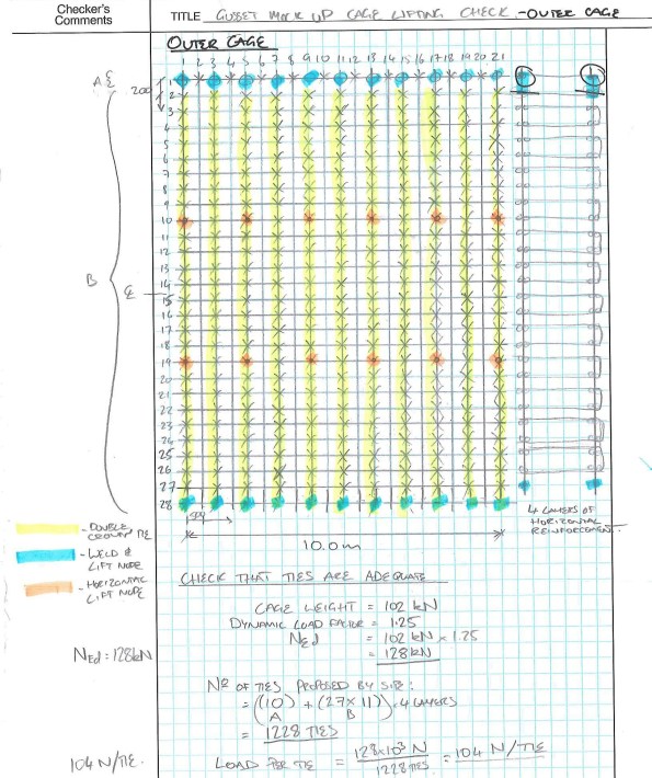
Proposed tie and weld arrangement. Still less conservative than the original design.
Ties themselves are difficult to quantify although tensile testing exists. An assumed SWL of 254N (25kg) gave a FoS of 8 from tensile test results. I couldn’t find out where that SWL was taken from. It seems rightly high in FoS terms given the risk of corrosion, human error in tying and damage. Future testing of tied wire is in the offing which should provide data for my TMR on the subject. I expect the variance between samples to be greater, and still quite difficult to pin down. However, any improvement in capacity reduces the amount of work for the steel fixers which equals fewer hunchbacks and less knackered wrists!
Working in the office is a noticeable step change from the site. Namely, that, a lot of people wear headphones all day and there are fewer threats of violence or general harassment. When I told the animals on site that I was going to work in TW they said that I’d be responsible for adding zeros to the budget and making things difficult to construct. On reviewing a small work package for welding to reinforcing cages I have observed how this can occur. I have also seen how easy it is to specify something that is overdesigned or even unsafe to construct. Particularly as they do not see many pairs of eyes before heading out the door.
I’ll hopefully have something more coherent and of note to post soon.
Dan
Rising Foul Main Connection Detail
I am trying to specify a connection detail for a 50mm rising foul into a 100mm dia gravity sewer. Peak flow is 0.05l/s, assuming 50l per person per day and 15 people. I have read about septicity causing illness in rising mains, Wessex Water describe it as:
- A common problem with foul pumping stations is a combination of low flows and long retention times. This results in bacteria multiplying in the anaerobic conditions. This is called ‘septicity’ and can occur in wet wells or rising mains.
I think that I need to provide a break chamber to slow the flow prior to it entering the gravity manhole. The design information does not specify how the connection is terminated, and as the design life is 10+ years septicity could cause a problem. Practically speaking, it will prevent the inside of the manhole becoming ‘splashed’ by high pressure flow.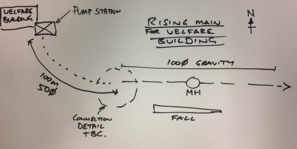
If anyone has any experience on such connections it would be appreciated.
Thought it would be a useful issue especially for providing such infrastructure overseas and the need to control disease/illness.
Cheers,
Dan
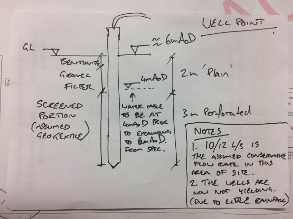
Reactive Dewatering
The excavation in which I am working is affected quickly by rainfall and subsequent water ingress. These wellpoints were installed as a reactive measure to lower the GWT prior to excavating to formation – the level pictured. They were only installed circa 10days ago. Does anyone know if the Corps have dewatering capability? The wells are connected to a Sykes portable pump then into a tank. Groundwater is separated from run-off (which is collected in sumps) due to potential for contamination.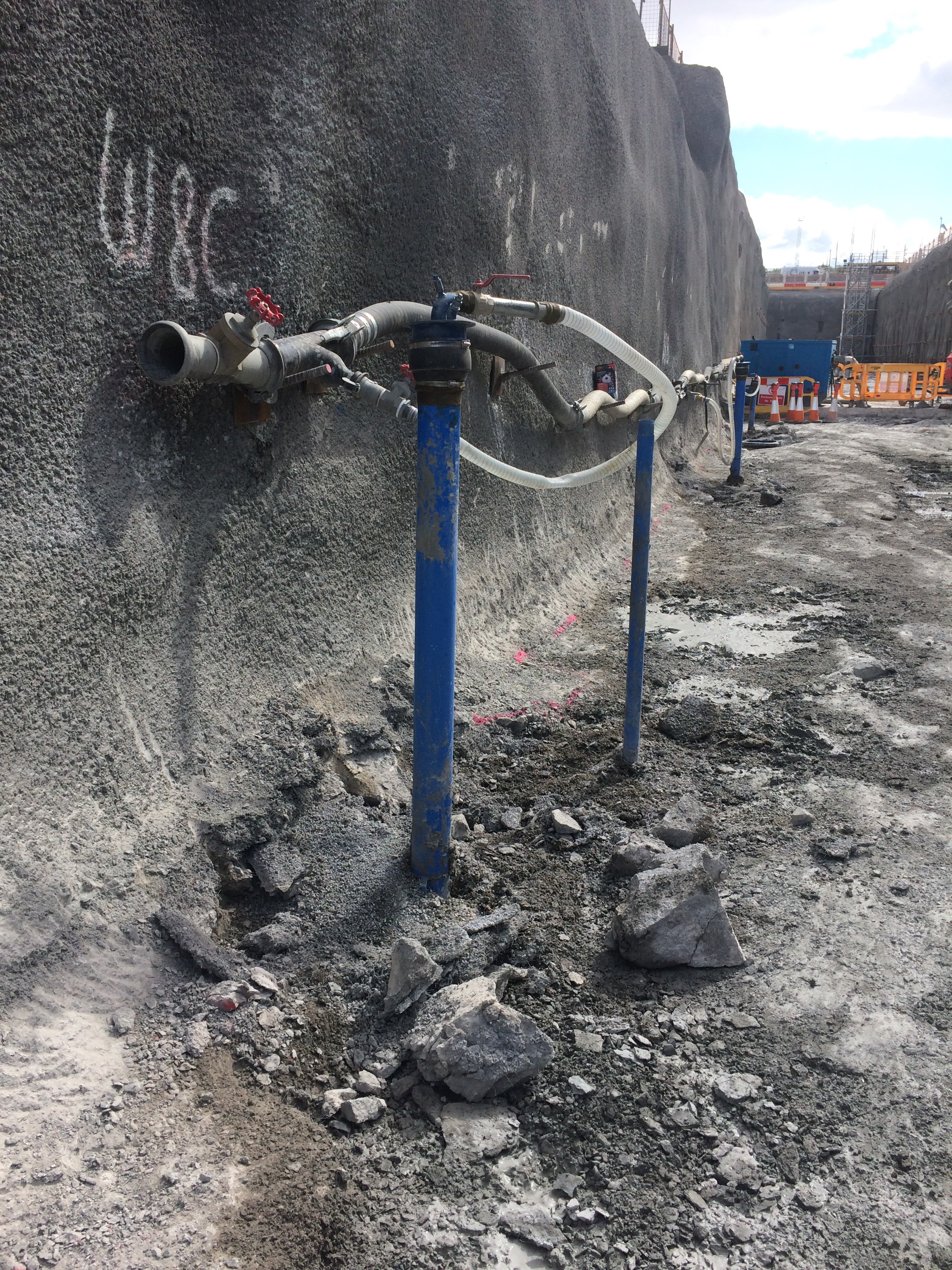
10-12 l/s is for slightly deeper wellpoints, therefore sub 10l/s is more likely.
Down hole testing – Tentative geo based post…!
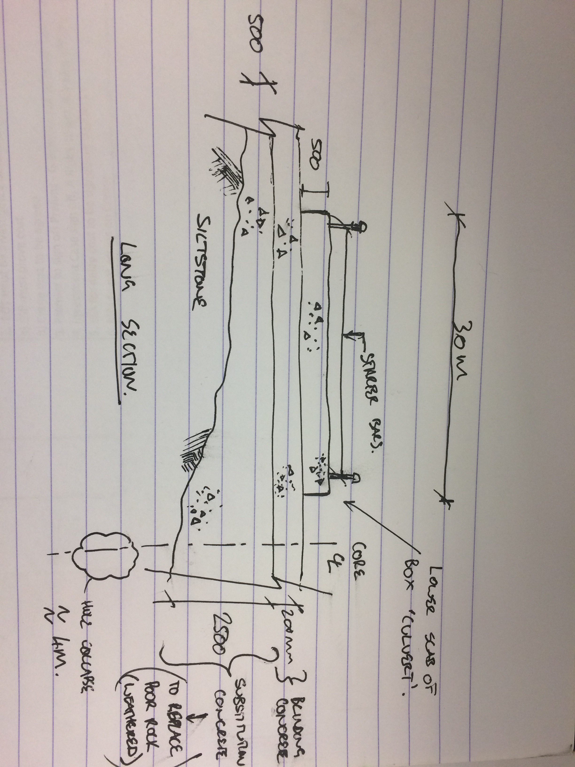
I’ve been told to oversee the use of a Menard test to validate the formation of some substitution concrete that was poured in almost submerged conditions. I.e water was being chased out of the 30m x 15m x 2m excavation by the concrete. Testing came about as the regulatory body was not best pleased about the whole thing.
Menard tests give a horizontal total stress to allow the eventual shear strength to be calculated. The picture is of the Menard assembly that is placed down the hole and expanded with gas and water in two separate membranes to give a pressure. This is repeated at different depths, normally from deepest to shallowest.
Issues are as follows:
1. They are struggling to keep the hole open to get the required membrane Volume for the test to be valid. About 60cm3.
2. They are trialling the use of a polymer in varying quantities (pure bore I think) But the polymer is too viscous and the pump pressure is getting too high. Possibly due to the trial area being on rock that is better than the siltstone which the real test was specified for.
3. The whole thing is becoming time critical as it is the second go we have had at it.
Could an SPT test give a similar result? Or is it too crude?
The use of Menard was a method specification given by the principal contractor geotechnical engineer. So the risk is ours.
Any thoughts would be appreciated.
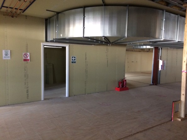
Service clash and visualising drawings.
The East Office at Hinkley Point is a 13,000sqm building formed of 12m x 3.6m x 3m modules. Currently undergoing first fix services it is the furthest along of three similar structures on site – it is not yet water tight but that is a different issue.
This post is just to quickly share the issues that have been experienced on my area of the site regarding service clashes, particularly drainage.
A 3D model was constructed for the building – clash detection was said to be acceptable. Foundations were constructed by another contractor on a contract with the Principal Contractor. The modular building contractor approved the as built strip founds by survey prior to beginning install of the modules stating that the greatest disparity in the service pop ups was +/- 40mm.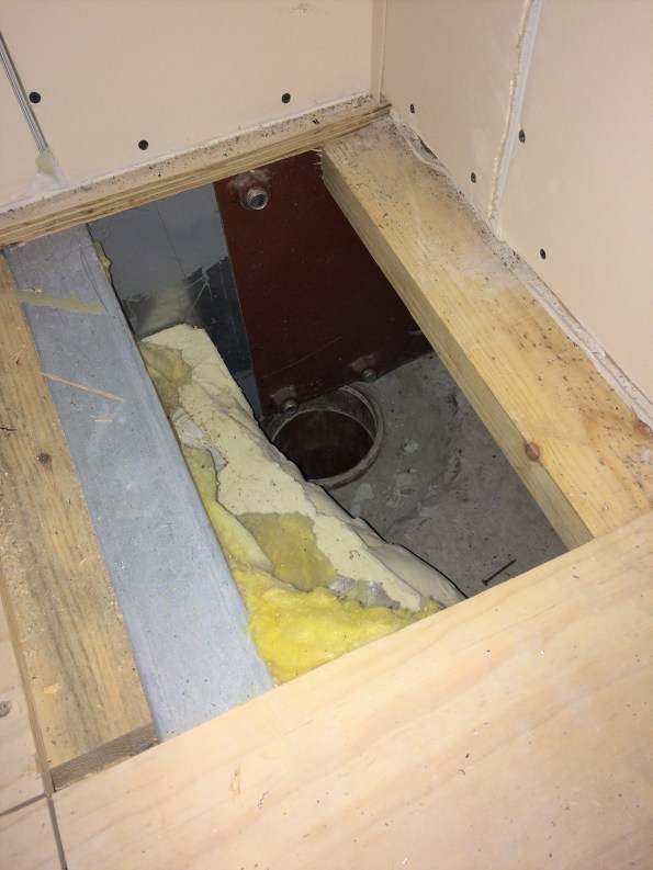
The intent was for vertical soil stacks to connect directly into the waste pipes from WCs in the corners of each unit. This did not account for the steel plate in the corner of every unit to allow attachment of plasterboard or for certain units to have their beams sit directly on top of the service pop ups. I advised (as PC we can’t do anything else) that they cut holes in the plate, as they were going to install a series of flume like bends which would mean additional boxing in. It also meant the plumbing sub contractor taking on risk from straying from the design which was unfair on his part.
Also, I think John mentioned always to check cross-sections rather than just look at plans. I have seen this first hand as a kitchen extraction duct is being installed that allows only 2.2m headroom, not including a floating ceiling to be installed. The spin off from this is that if this duct is not changed it creates a ceiling void above 800mm depth, thereby requiring fire detection or sprinklers. The duct also (as everyone who has seen it agrees) looks odd. Which has been enough to get the designers down to have a look this week. The duct is extraction for a reheat kitchen, yet it is twice the size of the same piece of kit for a proper kitchen in an adjacent building. Maybe a spec issue or stray decimal point.
The M&E, although not what I wanted to be involved in, has been an education in project life cycle and the importance of understanding what drainage goes where prior to casting concrete, signing off surveys, properly visualising the end result of an asset or committing to a design in the case of the extraction ductwork. With time pressure it is not as easy to be as thorough in some areas viewed as less critical but it is often the details that cause bigger problems from what I have seen over the past 7 weeks.
Hoping to get mud on my boots soon or at least within touching distance of a bit of plant (within the safe zone, having filled out the requisite forms etc).
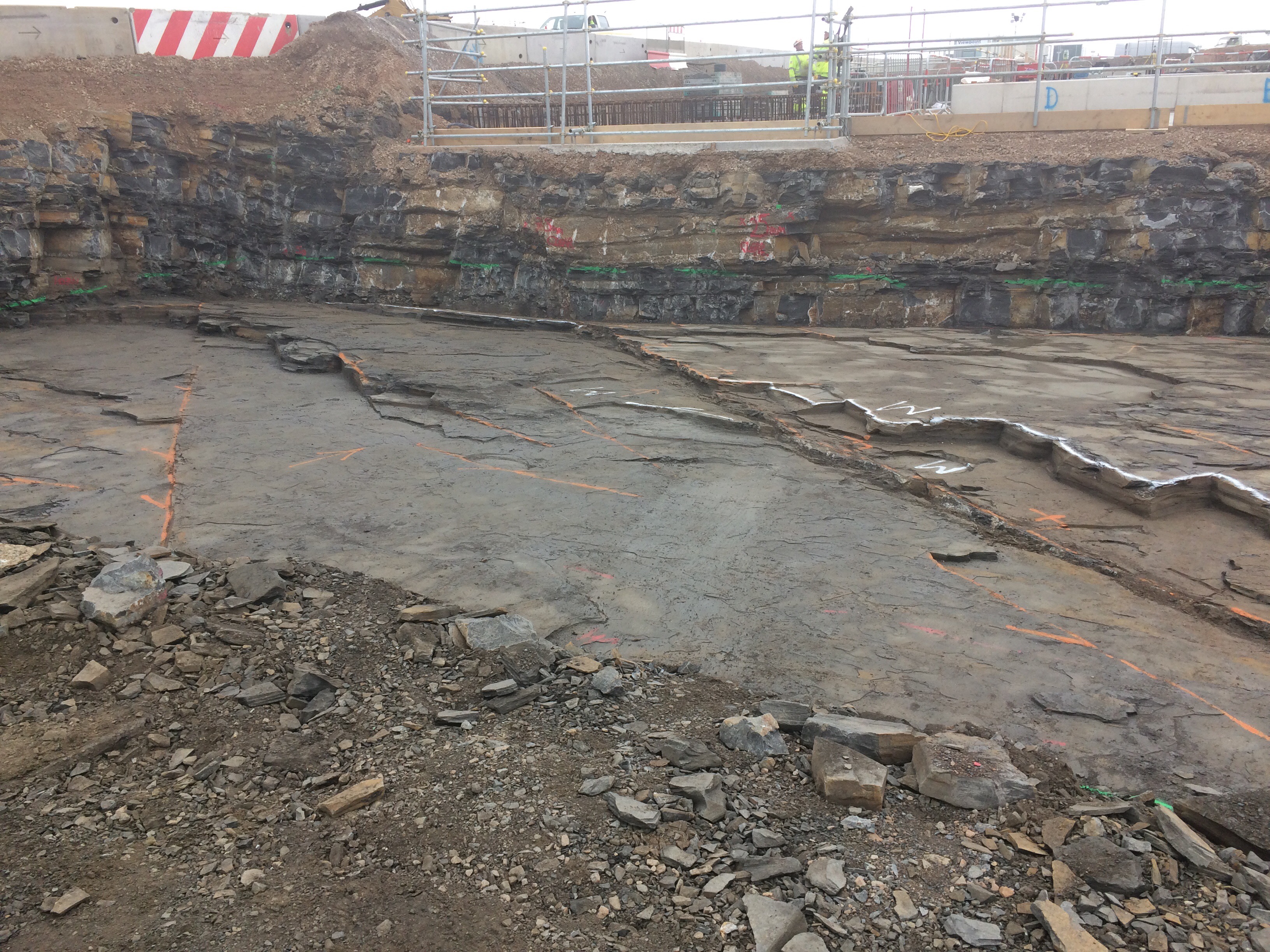
Formation level at Hinkley Point C
I’m currently not allowed to upload photos onto this site – I’m trying to sort out permission from site. So I will keep it brief until I can provide a decent intro to site with some phots. I just wanted to show the formation level on the site where I will be managing the install of the main site office (OIC portacabins). There is a 48hr exposure rule due to oxidisation of the ‘blue lias’ rock which can become weathered very quickly, so I’m lead to believe. So the inspection and blinding is fairly slick to minimise further excavation to fresh rock. Is this level of cleaning excessive in your experience? Or good practice? (Conscious that this is a picture – but it’s just stones) Dan Porteous.