Archive
Construction – has it really changed?
Most of my time with RPS Consultancy has been spent analysing existing historic dock structures. I have been working on a design and build project to construct new infrastructure for the Royal Navy’s new frigates in Glasgow. In order to make alterations to the dock structure it is necessary to understand how the existing structure works. As a result, I have spent a great deal of time trawling through old literature sourcing information.
Recently, I found the following photos of the construction of a dry dock in Scotstoun in 1903. It occurred to me that, whilst there is no hi-viz and no fall protection, very little has changed in the world of construction.
Coincidently, my principal take-away from this analysis is that modern design codes are overly conservative. According to Eurocodes these docks should not be standing.
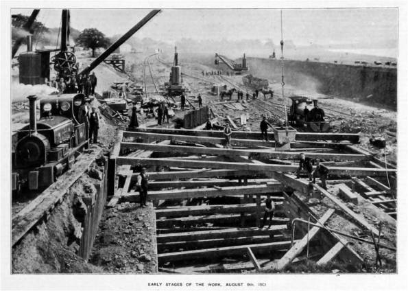
Dry Dock 1 – 1903
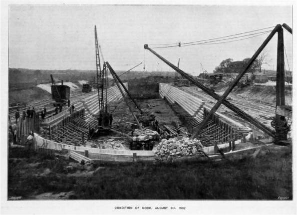 Dry Dock 1 – 1903
Sustainability Initiatives in Practice?
Recently, I have been on the periphery of some environmental work by RPS and I thought it may be vaguely interesting for the blog.
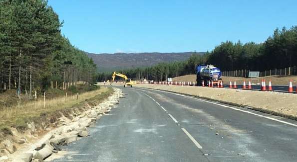
A9 Upgrades – Proof that the sun does shine in Scotland
As part of highway improvement works north of Perth, a Joint Venture of Wills Bros/John Paul is upgrading a 7.5km section of the A9 between Kincraig and Dalraddy. The scheme passes through the Cairngorms National Park, Alvie SSSI (site of specific scientific interest) and a tributary of the River Spey SAC (special area of conservation).
The project has required the management of numerous protected habitats and species during the construction schedule and RPS has provided Environmental Clerk of Works (ECoW) services.
My involvement has been compiling some reports but I thought it was interesting how much effort was expended on a relatively small contract (value £35m). The ecological highlights of the project included:
- Translocation of some 45 Hairy Wood Ant nests in collaboration with the Cairngorm National Park Authority. Hairy Wood Ants are included on the Scottish Biodiversity List as a priority species for conservation. They are a key stone species of woodland ecosystems and are threatened through habitat loss.
- Sensitively felling of mature Scot’s pine forestry containing Red Squirrels in consultation with Scottish National Heritage. Red Squirrels are protected both under UK and European legislation.
- Installation and monitoring of Otter fencing surrounding the development to protect this qualifying species of the adjacent River Spey SAC.
RPS ECoW services involved monitoring of compliance with all relevant environmental documents. In short, RPS was the contractor’s own environmental police. The environmental element of the project was considered a great success. The successful translocation of the Hairy Wood Ants was praised by the National Park Authority and the sensitive removal of forestry ensured a negligible impact to the local Red Squirrels population. Whilst the Otter fencing monitoring gave confidence to SNH that the development caused no likely significant effect to the nearby SAC.
From my cynical perspective it is interesting to note that the effort expended in aid of the environment has been rewarded. RPS site team have received high praise resulting in a score of 9/10 (“exceptional”) for environmental protection under the Considerate Contractor Scheme. The benefit of the full time environmental presence was recognised by the stakeholders. They had confidence that regulations were being followed; the site achieved a very high score for “Protection to the Environment” in the Considerate Contractors audit which rated the site as “Excellent”.
Maybe some of the environmental sustainability initiatives do work?
RPS Design Consultancy Belfast
As with all my contemporaries I have moved to the Design Office. My attachment is with RPS Consultants in the Belfast office and I am working within the Maritime Infrastructure Department. This blog is a brief scene setter so that my follow on blogs make sense.
![]()
RPS
RPS Group was founded in 1972 as Rural Planning Services (RPS) and labels itself a multinational energy resources and environmental consultancy company. The company is headquartered in the UK. In the 90s RPS expanded into Europe, North America and Australia. The company now employs over 5000 people worldwide, has an annual turnover of approximately £500m and in 2015 made a pre-tax profit of £57m
As part of the company’s expansion RPS Group acquired Kirk, McClure & Morton – a small sized consultancy, based in Belfast. The office employs approximately 200 employees. There are six departments, typical of many civil engineering consultancies: Waste & Energy, Transportation, Water & Environmental, Planning, Structures and Maritime Infrastructure.
BAE Surface Ships
I am employed on the BAE Surface Ships Initial Enabling Infrastructure (IEI) project. The contract comprises the design and construction of works to facilitate the build of The Royal Navy’s new Type 26 Frigates in BAE Systems’ Glasgow Shipyards. BAE Glasgow contains two shipyards along the River Clyde. BAE uses a modular approach to build the warships at two River Clyde sites; Govan and Scotstoun. The ships will be constructed in modules within large fabrication sheds at Govan. These modules will be welded together on a slipway on one shipyard and transferred onto a barge for launching. After the vessel is launched, it will be taken down river to another shipyard Scotstoun for final fit out and trials.
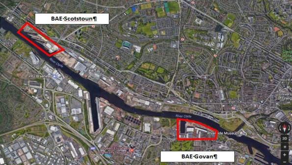 BAE Systems Glasgow – Two sites on the River Clyde
Initial Impressions
With a “smaller” consultancy I believe I will be exposed to a wider variety of engineering design rather than being pigeon holed in a particular design discipline/project. The counter to this is there is no dedicated specialists (Geotechnics for example) and knowing the SME requires knowledge of which personality designed the last/similar project.
The BAE project has a great deal of engineering design; in essence heavy Civils refurbishment/modification of old dock quays. Unfortunately, there appears to be a fair bit of Geotechnics which is disappointing as I was naïvely hoping for 6 months of steel portal frames…
Finally (and most importantly) it is great to spend some relaxing time at home with the family as the photo shows.

Paddy and Caffreys
Load Testing with a Difference– 25 NOV 16
So Bridge 1 is complete. This is the temporary structure that cuts across our site and provides access to adjacent phases. Its construction will facilitate our basement excavation in due course. Broadly speaking it is a motorway over bridge. It spans 80m over 9 spans (the largest of which is 18m) has a 7.3m carriageway with a maintenance footpath on either side. It has been delivered on time, on schedule and possibly to budget… Probably not to budget as the client’s scope was so vague that the trade contractor has taken him to town with additional items. I have spent the last month or so compiling Site Instructions to complete the bridge in line with the client’s intent.

Bridge 1 Aerial View – An adjacent phase 40T artic can be seen on the bridge ready to be offloaded
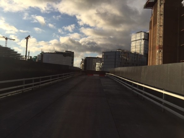
Bridge 1 – Deck View
Most recently, I have hosted a series of visits from various client representatives that have not just moved the goal posts but completely changed the sport… The design brief was cast in stone well over a year ago. The structure of the temporary bridge was to be designed as a private access road and therefore Highway regulations did not apply in their entirety. Clearly, the client and designer cherry picked areas (crash barrier rating and bridge loading for example).
From my perspective, the past month or so has been challenging, the client’s expectations are wholly unrealistic. My “favourite” client check was the load testing dry run conducted last week. Photos below:


Porsche Load Testing
The test to confirm the ground clearance for sports cars was successful as the Porsche did not ground out at any point. However, from my perspective, given that the gradient was dictated by the existing road profile at the entrance to the site and the final road level at the permanent HALO Bridge. How could the bridge deck profile have been altered had the sports car test failed? Answers on a self-addressed postcard please.
REACTIVE NOT PROACTIVE
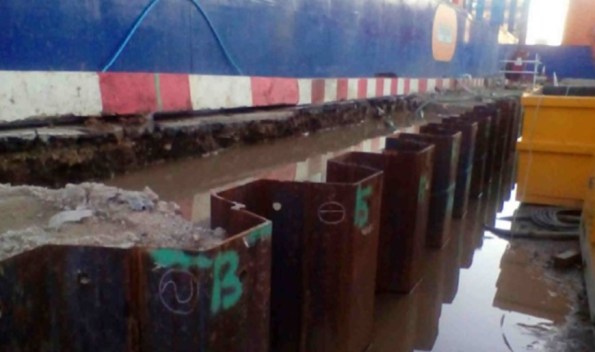
A series of events has unfolded over the past few weeks which has reinforced my utter contempt for the reactionary nature of site works; a common theme on Phase 2 WhatsApp chat. BPS Phase 3 basement is a 13m excavation, 16m in some locations. Along the southern boundary (adjacent to the Northern Line Extension site) the embedded retaining walls used are sheet piles. The contractor is unable to use vibratory hammer techniques to drive the sheet piles due to the proximity of the largest brick clad structure in Europe (Battersea Power Station). The 23m long sheet piles are thus driven using a silent press. The geological succession is typical London stratum. Made ground (crap), Terrace Gravels (medium dense sandy gravels – very porous), London Clay (very stiff – not very permeable) and Thanet Sands (very dense silty sand – porous). Due to the required toe depth, in the London Clay, pre-augering and water jetting techniques must be used. For the civils students the problem bears remarkable similarities to Ex COFFER.
The following photos below provide an indication of the works.
 Pre-augering Works
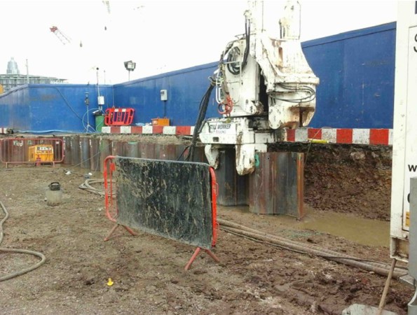 Sheet Piling Works using the silent press
 The aftermath of Water Jetting
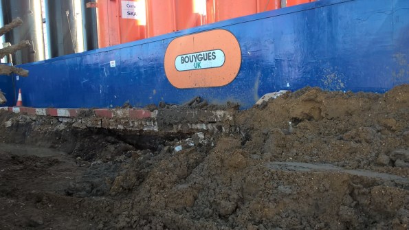
The Inevitable Collapse
The previous photos show the steep batter adjacent to NLE site and there is a risk of undermining the adjacent site. However, sheet piling works continued whilst the contractual wrangling from the piling contractor and ground worker simmered in the background. Both parties claimed the other was responsible for fixing the problem. The inevitable happened and the batter gave way, undermining the NLE site, next to Polymer tanks. This incident has added further friction and incurred additional expense as BPS Phase 3 must repair the damage to NLE site. All in all a foreseeable incident that could have been avoided if stakeholders had looked beyond their blinkered “it’s not my responsibility” approach.
 Batter Collapse
My original comment: “utter contempt for the reactionary nature of site works” may seem a little unfair given the circumstances detailed above. Never-the-less I think my comment is well founded given the final photo taken AFTER the batter collapse which was the piling contractor’s response to dealing with one of the contributing factors (disposing of the excess water)…
 The contractor’s solution to the excess water – discharging the water behind the sheet piles further washing away any batter! However in their defence apparently contractually: “It’s still not their responsibility“
Battersea Power Station Phase 3 Update
I realised I have been a blog voyeur and not participated a great deal so I thought I would provide an update.
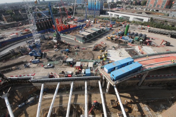
Photo 1 – Site today.
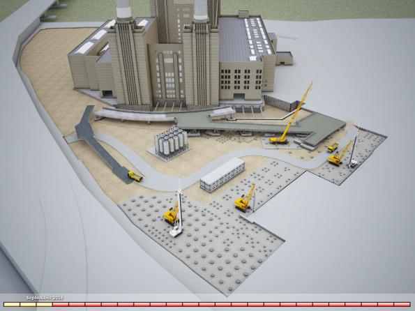
Photo 2 – My task – Bridge 1 CAD image (NB existing ramp visible on left. The existing ramp is visible from the train when travelling into Victoria).
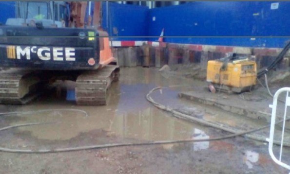
Balfour Beatty Ground Engineering has nearly completed all piles (nearly 300) along the line of the first temporary bridge structure (area A). This has allowed McGee to commence construction of the pile caps that the bridge structure will sit upon. Points of note. Photo 3 shows Dolphins 7, 8 & 9 (the terminology for the RC sway frame that the bridge steel decking sits upon). The pile cap for dolphin 9 has been poured, the rebar for dolphin 8 is being fixed and the blinding has been poured for dolphin 7. There is over 140m^3 of concrete in the pile cap and when the excavation commences this pile cap will sit approximately 13m above formation level.
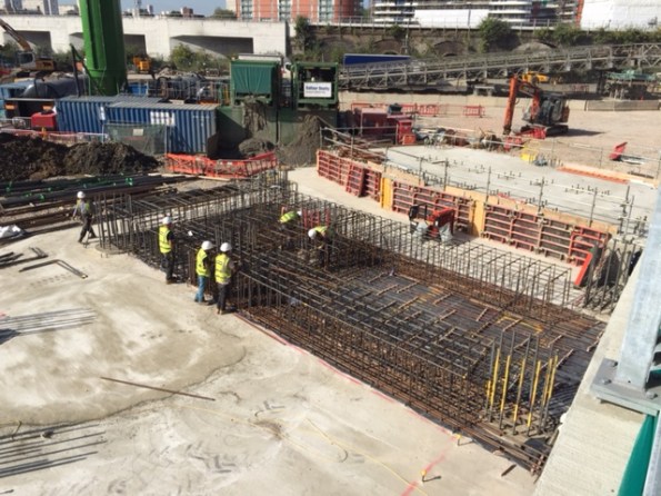
Photo 3 – View of ‘Dolphin’ 7, 8 & 9 with pile cap 9 poured, rebar for pile 8 fixed and over 40m^3 of blinding for Pile cap 7.
In tandem DAM structures have commenced fabrication of the steel deck structure and I have conducted a number of visits to East Yorkshire (‘Brid’ as the locals call it). All of the sections are ‘standard’ road haulage dimensions to avoid wide loads. The bridge deck comprises three 2.4m wide sections plus edge sections – Photo 4 shows a standard bridge deck on its side in order to weld the steel plate that makes up the road surface.
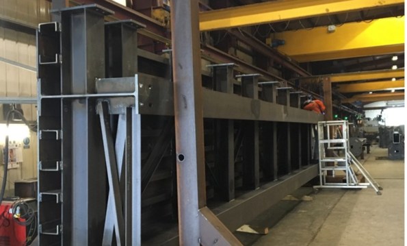
Photo 4 – Steel Deck Sections in the fabrication shop (This is a ‘normal’ deck section 2.4 m wide, 12m long and weighs approx. 13T) .
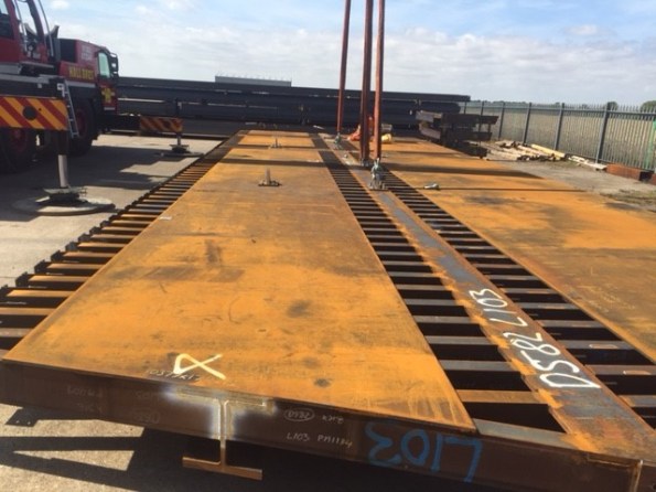
Photo 5 – Practice lift and erection in DAM Structures yard (these are special deck sections that connect to the existing permanent bridge).
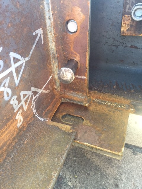
Photo 6 – Connection detail.
Interesting ‘stuff’ going on:
- Contractual wrangling is still on-going.
- Bouygues UK has not signed a contract and is moving toward a construction management role.
- BBGE has not signed either
- McGee has finally signed on the dotted line.
- We had a spate of safety issues but they pale into insignificance compared to Kukie so I will not bore you with them.
- Too many piling issues to mention from pile rig failures through to changing ground conditions and everything in between.
Bit of a long post – apologies James!
SITE BOUNDARIES AND INTERFACES WITH ADJACENT PHASES
I have been struck by the interface between our site and the adjacent phases, in fact it was my overriding first impression on attachment. The interface issues have featured in my reports and my daily routine involves a great deal of liaison and de-confliction with adjacent sites. We have recently been constructing some temporary plinths atop a permanent structure that Phase 3 temporary bridge will sit upon and whilst conducting a pre-pour check I thought the following photo perfectly illustrates these interface issues.
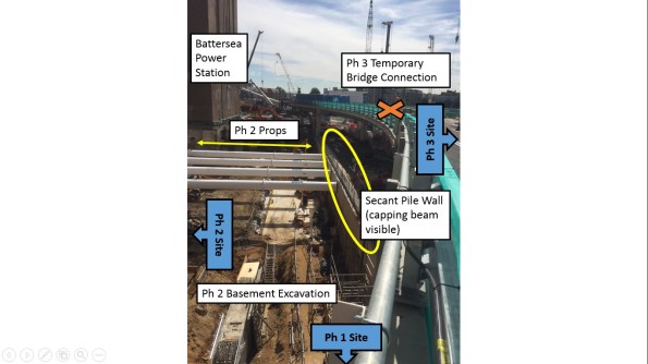
- The photo is taken looking eastward along the permanent structure (Halo Road).
- This road will provide access to Ph 1 (Carillion) for residents when the development is occupied later this year.
- Ph 3 (Bouygues UK) temporary bridge structure connects to this permanent structure (hence the plinths)
- Ph 2 (Skanska) are excavating their basement levels.
- Temporary Props have been installed in order to transfer the loads to the secant pile wall.
- Construction sequencing for Ph 3 still has to be confirmed in order to excavate basement levels on ‘our side’ of the secant wall.
- Just visible is the heating pipes that run from an M&E plant in Ph 2 across all phases to Ph 1.
As I have said previously, this is not the most technically challenging work nevertheless it is fascinating and a solid education for myself.
Spot the Obvious Mistake
Following on from my previous Blog Post: “A wheel wash – yes honestly the story of a wheel wash”. My exciting challenge to all bloggers is to spot the obvious error ( I hasten to add I am afraid this is not an interesting geotechnical issue).
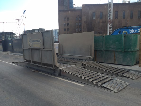
A WHEEL WASH – YES HONESTLY THE STORY OF A WHEEL WASH
Occasionally, I read others blogs and I despair – I am not dealing with safety critical testing, I have not touched out of tolerance piles and certainly not experienced the delights of BIM. Instead I have been busy dealing with the position of a wheel wash… That is correct, the complexities of where to place a giant car wash on steroids. As an aside, the site right next door doesn’t need a wheel wash as NLE use a conveyor and barges to dispose of their spoil. In the process they stockpile all their muck right next to our temporary sheet piles creating surcharge loading that no-one has considered. However, that story is for another blog.
The Problem
Approximately 120 muck away tippers per day, scheduled to increase, when Phase 3 start to excavate the basement levels. A shared access route – Phase 1 (Carillion), Phase 2 (Skanska) and Barhale are all on site (as principal contractors). To further compound the congestion Thames Tideway preparatory works have closed one of the public access roads. Finally, the location of the wheel wash must not clash with permanent structure works. The sketch below shows the access route highlighted in red with the locations of the different Phases and the permanent bearing piles, temporary sheet piles, and permanent secant pile walls.
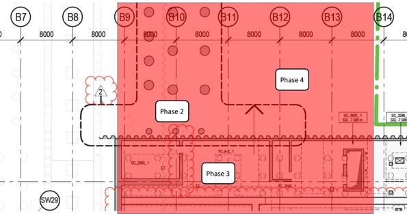
Phase 3 Entrance – Showing the permanent pile locations (red shading access route)
The Solution
My previous blog discussed the requirement for collating detail from all stakeholders. Well, nothing has changed and once again a great deal of my time has been spent arranging meetings. This time it has concerned the interface with the other phases. I have spent numerous hours with McGee (Phase 3 ground works contractor), Bouygues UK methods team (from a construction phasing perspective), Skanska (Phase 2 Principle Contractor), Blu 3 (Phase 2/client’s ground work contractor), Keltbray (Phase 2 sheet piling contractor), Clipfine (BPS site wide logistics and security) and frankly a host of muppets from the clients side… The solution is shown below and as one can imagine this is not an intellectually challenging issue, nor is the solution technically difficult – the draining aspect of this managerial issue is dealing with a group of people who appear incapable of making a decision. It highlights the difficulties of project management on a multi-phased development and is potentially my next TMR.
I am sure you will all have thought of the solution – A single wheel wash directly procured by the client for all Phases but why this has not been done; only the muppets that I mentioned above can confirm!
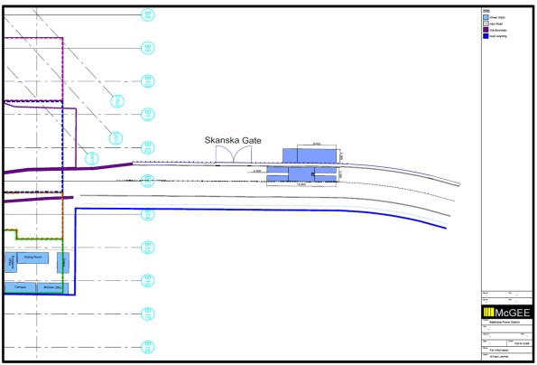 Phase 3 Wheel Wash Location – in the final agreed position (hopefully)
The Devil is in the Detail
Phase 3A must construct three large temporary bridges that provide access through our site – both for adjacent phase’s construction traffic and future residents. The 3D CAD model below provides an illustration. I have responsibility for bridge 1. The bridge section spans over 54m and it has two decks of 24m length at either end. It will be suspended 18m above formation level (when we eventually dig down to basement 3 level).
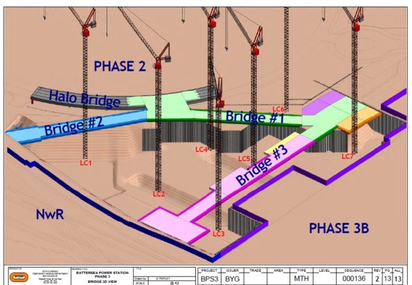 Temporary Bridge Structure – 3D CAD Model
The Problem
Bridge 1 must be in place to allow residential occupation of Phase 1 (Carillion’s site) in Q4 2016. As a result, the client’s driver is time. Unfortunately, the temporary bridges have been designed in isolation to the permanent structure and only considered on plan. As one can imagine this situation has created many clashes.
The Solution
The Devil is in the detail and the solution requires all the stakeholders input. De-confliction is the name of the game and the majority of my time has been spent in meetings trying to work through solutions. The greatest difficulty lies in the area of the temporary bridge deck supports. These ‘dolphins’ (the nomenclature on the drawings) consist of piled foundations with high level pile caps that support the bridge deck. The drawing below illustrates the initial design with uniform spacing (coinciding with the deck spans).
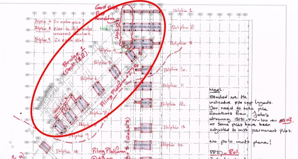 Bridge Supports – Initial Design (relatively uniform supports)
My task has been to knock heads together to come up with a mutually beneficial solution for all. I have convened meetings with the temporary bridge designers (McGee), the permanent structure designers (BuroHappold Engineering), the piling contractors (BBGE), the M&E designers (Chapman BDSP) and the construction sequencing team (Bouygues UK). The outcome of these painful liaison meetings can be seen below. One reason these meetings are so painful is because still no-one has signed a contract. Whilst not the most exciting Blog post the two photos represent a couple of weeks work and provide an idea of the small victories won. The next stage is to attempt to reduce the size of these temporary bridge supports…
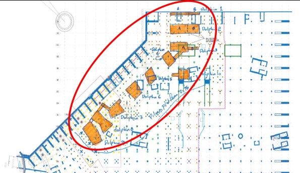 Bridge Supports – Post De-confliction (variable shaped supports)
