Archive
Industry Lessons Learned?
I received the following document (Dated April 16) this morning. At this early stage there is nothing to prove (That I have heard) the recent tragic accident is related to the issues outlined in this report. That aside, in the continued interest of professional competence and safety going forward its definitely worth a quick read.

Freds Giant Crane
I acknowledge that my last blog bored most of us to tears, so this Friday afternoon just before the office beer fridge gets cracked open for the weekend I thought I’d follow it up with a topic even the E&Ms might enjoy.
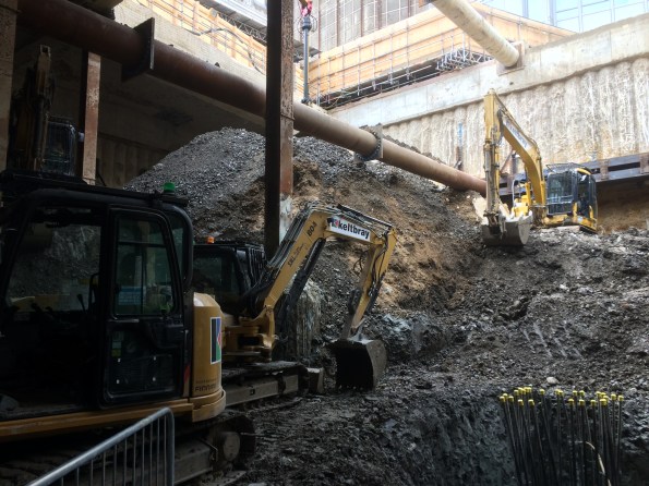
Hopefully some of you will remember Fred’s blog a few months back in which he essentially implied he had designed use of one of the worlds largest land based crane systems during a morning coffee break. I had the joy of visiting Freds crane earlier this week on CPD. It really is impressively large. See below some photos and a few basic stats I picked up whilst there.
Its currently supporting removal of very large reinforced concrete beams as part of the demolition job on the Earls Court Job. The demolition package alone, including this crane, has a contract value circa 28 million quid.
![IMG_5113[1]](https://pewpetblog.com/wp-content/uploads/2017/06/img_51131.jpg?w=595)
In its strongest configuration the Crane can lift 5000 tonne. On this project the greatest load they will lift is just under 1600 tonne.
The load is transferred to ground through steel pads onto a compacted earth foundation and generates a bearing stress of 0.28MPa.
![IMG_5111[1]](https://pewpetblog.com/wp-content/uploads/2017/06/img_51111.jpg?w=595)
Giant lifting tackle, required just to assemble the crane.
![IMG_5115[1]](https://pewpetblog.com/wp-content/uploads/2017/06/img_51151.jpg?w=595)
The crane moves when the grey hydraulic jacks drag the legs along the rail. The silver disks are Teflon pads which create a low friction channel. The gang genuinely lubricate these runners with washing up liquid before each move.
![IMG_5119[1]](https://pewpetblog.com/wp-content/uploads/2017/06/img_51191.jpg?w=595)
The crane has a maximum operational reach of around 130metres. At this range it can lift approximately 300 Tonnes. When you consider a standard tower crane can lift roughly 3-4 tonnes at a maximum reach of about 70m these are impressive stats.
All these fancy figures aside, for me the most impressive implication is that deciding to use this crane has saved the sub contractor, or so they say, 3 years on their demolition programme. I hope the person who actually came up with this plan got an appropriate bonus for his lightbulb moment!
Pingo Bingo
Last week Beresford tricked me into attending what I thought would be a notoriously dull lecture at the Royal Society of Geologists. The talk was on a ground condition known as a Pingo, or using its more technical name, Drift Filled Hollows. It turned out to be mildly interesting because the ‘expert’ openly admitted that Geological understanding of this condition remains relatively basic at the moment and from engineer’s perspective, the implications for a large structure are potentially very severe.
To try keep this short, a Pingo is basically an unexpected disturbance and variation in the ground strata caused by (they think) perma frost occurring in the ground some millennia ago. This created a hole which is then essentially filled with differing material over time. In the London Basin this is an issue because it means, where you might expect to find a decent band of London Clay there could actually be a column of terraced gravel, or another material, penetrating to significantly greater depth.
The following image shows a cross section of the anomaly discovered during the Blackwall Tunnel project.
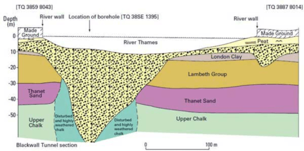
Some of these anomalies have been found to be more than 90m in depth and have relatively small surface areas. This is potentially a problem because if you insert a large load bearing column designed to use skin friction from the London clay, Lambeth group or Thanet sand, and it actually sits within a deep column of terraced gravel, the performance of the pile could reduce significantly. An Engineer in the audience stated that if you double the Pour Water Pressure the bearing capacity of the pile roughly halves. Clearly permeability in the terraced gravel is considerably greater than the clay.
This issue is even more of a problem because you could conceptually have a Pingo anomaly positioned between site bore holes. This means that you might be unaware of the issue on site until the point the pile is being installed. This is obviously too late in the day simply because by the point piles are being installed the design of the building and its foundations should have been finalised.
As I left the lecture it occurred to me this might make a decent thesis topic for a phase 2 student currently struggling for ideas. It looks like the Geologist lot are working hard to collect data on this issue. Combining this data with a detailed look at the risks a Pingo presents from a civil engineering perspective might prove interesting.
Laurie’s added site product from Phase 2
City Pollution – Old Habits Die Hard
In the sustainability study group this morning we discussed the Construction industry and current lack of regulations regarding control of plant vehicle pollution. The following link takes you to an article that discusses the problems with construction plant pollutants in London and the challenge of regulating them in an industry where enforcing higher standards would generate absurd replacement costs.
It turns out that a lot of plant equipment currently used in London is Red diesel powered and outrageously inefficient. One of the Geo boffins told me they had recently received some environmental data from a site showing that it currently takes one piling rig 1000 litres of diesel to bore every 60m deep pile. There are 74 of them on the project!
The construction industry might grind to a halt if the Government begins to pay as much attention to plant equipment engines as they do VW diesel cars.
Engineer Sketching – Recommendation for Phase 1 and Phase 2 Students
This is hopefully a quick blog with a basic recommendation aimed at Phase 2 students just writing their first TMRs and the students about to start Phase 1 at PEW. It’s probably a bit late for Phase 3 students just finishing off thesis.
Since starting work in the design office I’ve been surprised at how much time I spend producing sketches and technical engineer drawings. Id say approximately 55% of my hours are committed to this work rather than reading through code or churning the calculator. This is because the main method of communicating technical design detail is with sketches and drawings and generally clients/subcontractors tend to miss information contained in text when analysing a dwg. So far I have worked on three types of Dwg/Sketch:
- Engineering Concept Design – Used to provide general information on the way in which something is built. These are most commonly used in method statements and design proposals. As these are general concept dwgs they are normally produced by the Engineer because it is cheaper and quicker than getting a Draughtsman to do it. They still go the client so therefore need to be reasonably professional.
- Calculation Sketches – These sit in my calculation pack and are there to add context to a calculation process. Generally these are internal and are never formally assessed so these are quick and rough.
- Formal Drawings – These are the output Dwgs from weeks of design work and are the main method of relaying information to a client. These therefore need to be highly detailed, professional and accurate. As such these are always produced by specialist Draughties using CAD. This can take ages (weeks) and is very expensive, as such we only use this method when absolutely necessary.
So the advice focuses on the first of these three. I am terrible at making Dwgs look neat and professional. I spent a few weeks wondering how the guys in the office produced such exceptionally neat hand sketches. We even have a sketch of the month competition and my attempts were, until recently, a million miles away from winning.
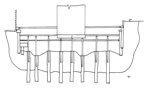
That is until I found out there is free computer software you can download that helps you make rubbish hand sketches look good! As I started using it this week I thought it would be helpful for those students producing Dwgs for TMRs or those on Phase 1 producing sketches for the design problem coursework. You produce your rough sketch, scan it in then edit and add detail as required.
Here is my hand sketch, using tracing paper, for one stage of a basement construction method statement pre-software.
And here are a couple of my sketches after some computer magic.
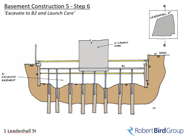
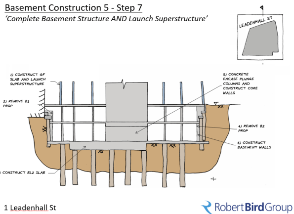
Still rough I know but a considerable improvement! The software is called ‘Gimp’ (no joke). I’d recommend downloading it and using it for coursework.
Sustainability through Design
Conscious that CPR is just around the corner and Sustainability still looks to me like a vague, tree hugging engineering attribute, I have volunteered to join the Robert Bird sustainability working group. Made up of engineers from varying disciplines (Geo, Temp Works, Civil’s and Structures) and experience depth/seniority, our objective is to develop a sustainability approach within RBG and provide focused support to ongoing projects.
In today’s meeting a senior project director asked us to look into a very specific client request to try understand the risks and opportunities from a sustainability perspective. In broad terms, the local planning department and client have mandated that 25% of all aggregate used in his project must be reclaimed. Though we have a 40 storey concrete residential structure in which we could potentially hide this high percentage of reclaimed aggregate, unfortunately the structural engineers have told us they do not want to use it in any columns or beams because they are concerned about its performance.
The interesting thing about this mandated condition is that we have no context to its origin or underlying intent. By that I mean we have no idea what the planning department aims to achieve by it or if it was just a random number plucked out the air by a Planning Department work experience undergrad ? Most of the team assumed it’s to reduce the carbon cost of the project. Someone thought it is intended to reduce the number of vehicles transported to site and one engineer suggested it is simply to save cost. At this point we don’t know.
Has anyone else encountered this requirement before and have any views on its impact?
We are now researching the following basic angles to increase our understanding of the options open to us.
- What is the key incentive for this planning constraint?
- If it’s to reduce the Carbon cost and we can’t get 25% reclaimed agg into the design, can we offset this shortfall with other C02 saving methods: ie use of GGBS or other cement replacement products?
- What are the structural issues with using Reclaimed Aggregate and how does it affect performance?
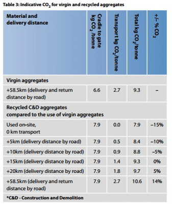
- At what point does using reclaimed aggregate actually add to the Carbon cost and are there suitable suppliers within range of task site? The following image shows that as the distance of transport to site exceeds 15km, the carbon saving is eradicated.
Anyone got any thoughts or experience of this stuff? In the meantime I’ll be chained to a tree at an anti fracking protest whilst waiting for answers.
Cheers
TD
TC Design – Practical Application of SA Techniques
It’s been some time since my last blog as I was away for a bit on holiday, it was great to see everyone out in Oz. I have now been back to work for a few weeks and am safely embedded in the Robert Bird Group (RBG) Construction Engineered Solutions (Temp Works) Team. I asked to go into this department in the hope it would allow me to get plenty of short, sharp tasks that would expose me to a broad range of experience whilst developing my SA skills.
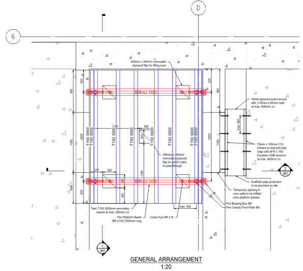
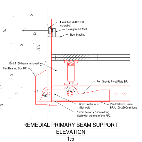
Currently I am designing an embedment plate for two Tower Crane Ties. The example below shows one of the double brackets specified by Terex that I need to connect to the embedment plate I come up with.
I was given un-factored reactions, also by Terex, all of which are acting at point A as annotated on the second Dwg.
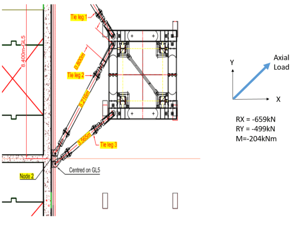
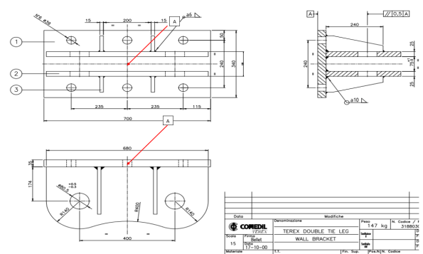
Put simply, I am trying to transfer the loads given into my reinforced concrete core wall. I started by factoring the reactions and conducting analysis on the back of the bracket to determine the maximum tensile loads likely to be seen in each bolt position (36mm dia bolts). Ideally my anchorage re-bars will tie into this plate with couplers that connect to 36mm dia bolts protruding through the holes you see on the dwg, also giving me the tensile load in my anchor rods.
For those who are bored or, particularly for those currently on phase 1 who enjoyed the SA exam twice like I did, it’s a good problem to get a feel for how the technical analysis skills you are taught on phase 1 are used daily in a structural engineer design office. Even after 11 months on site watching Irish blokes pour concrete it didn’t take long for me to get back into the swing of this stuff and weirdly, I’m now actually starting to enjoy it.For obvious reasons I was mildly apprehensive about this phase of placement but as it turns out I find it much easier now I can apply it to real world work.
I’ll try put up some of my workings in a few days but as a starting point you clearly need to design a solution that deals with all the forces acting on the bracket in this condition. The means by which you model this bracket significantly changes your loads. (Note: I also resolved this with the axial force in the opposite direction shown but as it gave a very favourable pre-stress the tension issue is negligible in that condition).
(Once you’ve done it using all three rows of connection points, try deal with the moment using only the central two bolt positions as this is a design constraint I am working through at the moment due to the geometry of the core wall).
Managing Temporary Works Risk
As most students will have noted on phase 2, TW can be a particularly high risk element of any construction project. For the last few months, in addition to my other responsibilities, I have been involved inspecting items as they are installed and during their ongoing use.
On a high rise building, a failure of TW in an unfortunate location can have exceptionally serious consequences, because people or items can potentially fall from very significant heights. As the Principle Contractor we are therefore supposed to provide a very thorough secondary control system. This involves scrutinising and inspecting the TW’s designed and installed by our relevant sub – contractors, who officially carry liability for their own systems. I have noted that more often than not TW are not installed exactly to the approved design as the guys on site have a habit of making unapproved adjustments. Whilst this is not acceptable, in many cases the implications of a failure are minor.
This morning whilst conducting a check of a TW system installed by our concrete contractors a colleague and I identified an issue that worried us significantly enough that I have decided to write a blog on it. The images below shows the design of a temporary access walkway platform suspended between two walls of our reinforced concrete core. It spans over a permanent lift shaft at level 10. To be clear, below this TW structure is a 10 storey, plus 15m of additional basement, vertical drop. i.e. If it fails and someone is on it at that unfortunate moment, that person is falling unobstructed down a vertical shaft for the best part of 32m, from floor 10 into our basement.
You can therefore probably understand why I got very upset when it became apparent (whilst I was stood on it) that this system had been installed, declared operational and used by numerous operators on site without the most basic conditions being met:
- The design process being completed in full with a final check signed off as status A by MPX (Principle Contractor)
- The installation being inspected to assure conformance with design by a competent MPX TW supervisor
- A permit to load certificate being signed by a competent person
It turns out they built this over a weekend and started using it immediately without anyone checking the quality of the installation. Even the sub-contractors own TW supervisor (The first layer of inspection) had not checked and signed off this installation prior to its use. In this case two of the key management safety layers had been completely ignored; highly upsetting when you consider that a failure of this system would almost certainly result in a fatal accident.

The TW platform prior to the installation inspection – Structural components cannot be easily accessed or inspected

TW Primary and Secondary Beam Installation Check
As the images above show, in this case we were eventually able to access the TW structure and confirm it had been installed correctly. Our main issue is that this process did not proceed us standing on it over a lethal void.
The TWprocedure exists for a very good reason. To provide multiple layers of review and inspection in order to best mitigate the risk of a failure and a subsequent accident. It is quite alarming how often sub-contractors prioritise programme and task progress at the expense of a thoroughly enforced, critical safety procedure, particularly on such high risk TW schemes.
Concrete Chaos
A few weeks ago we completed the first of our substantial concrete pour operations in order to construct the main tower core pile cap in our basement. This is a big block of concrete. The pile cap is roughly 18m wide, 36m long and 3.5m metres deep giving a total C32/C40 concrete volume, with quite a few lift pits thrown in for good measure, of 2830.5m³. We are constructing it in four roughly equal sections. During the first of these pours we emplaced 610m³ of concrete in one go. The pile cap will eventually carry roughly half of the 40 storey towers structural load so getting this right in terms of quality is important. This task was also on the critical path so ensuring it went in error free and on programme was a major concern. As the blog title implies, all did not go to plan.
Whilst my ability to walk over re-bar mats without looking like an amateur construction worker is improving rapidly, even I felt reasonably uncomfortable being stood on top of the cage suspended 3m in the air with clear sight to ground. The top mat re-bar inspection is probably the most unsafe I have felt at any point on this project. The potential to fall through a hole in the mat or beak an ankle/leg was alarming, as such work was stopped on multiple occasions to address H&S concerns. Thereafter I took to doing re-bar checks from Ground level looking up. Despite its considerable size the re-bar cage is a surprisingly simple design made up, in general, of 32mm dia bars at 200mm spacing’s. We have 4 layers in the top and 4 layers in the bottom.

Unlike most concrete pours the interesting thing about our methodology is that once the formwork is stripped away it’s conveniently easy to inspect a complete face of the pile cap throughout its whole depth. This makes post pour quality assurance checks considerably easier for the main contractor whilst also making it more difficult for the sub – contractor to hide any poor work underground.

The above picture shows the top 1.5m metre of our 3m deep concrete pile cap once the formwork had been removed. The structural engineers were initially quite concerned about the concrete quality. If you look closely you can see horizontal lines running in the concrete throughout its complete depth. Initial concerns were that the pour process had enabled horizontal cold joints to form between delivery loads of concrete. Had that been the case, then we were concerned we had produced a concrete block with weakened shear planes running through it. The question I tried to get answered was: why is this a problem? As I see it; If you simplify the pile cap in the permanent condition and consider it a large beam (the concrete block) carrying a large UDL (the tower) through numerous evenly distributed supports (the load bearing piles) then I think you would end up with a very simple FBD and BM/ SF diagram. With a few convenient assumptions and a quick check on google I think it would like something like the following
If indeed this pile cap behaves like a beam (And not a reinforced deep truss) then it sees greatest shear over the pile positions. Under the load of the completed building multiple horizontal cold joints caused by poor installation will undermine the capacity of the concrete pile cap, particularly in those positions. As it’s such a vital structural component stripping out this concrete and starting again was suggested by one overzealous member of the construction team. That was quickly put on hold because breaking out 610m³ of heavily reinforced concrete would be very unpleasant, not to mention crippling for our tight programme. As such an investigation was completed and after chipping away 30mm of concrete face the effect disappeared and with it the concern over the complete block. Had it continued we would have cored into the concrete block in a desperate search for any shred of evidence that would have prevented the need to strip it out.
Interestingly, even had we found weakened horizontal shear planes running through this mass of concrete, automatically stripping it out would have been a hasty reaction. When you look at it simply, all we need to do is install a solution that allows shear to be effectively transferred between the layers. Conceptually this could also be achieved by post fixing shear links into the pile cap by drilling and installing vertical reinforcement steel rods through the concrete. If we emplaced enough steel, focusing on the areas where the shear is known to be greatest, it is likely we could provide enough shear resistance to mitigate the long term risk. This would be difficult but considerably easier, quicker and cheaper than stripping it all out and starting again.
We are still unsure what caused this effect so consistently. In general concrete work seems reasonably poor quality across site. At the time I asked the concrete sub-contractor what lessons they had learnt and what measures they were putting into place to improve this process, they couldn’t give a particularly good answer; concerning when you consider our next pour was 850m³ of the stuff.
EXCAVATION MADNESS
In my 7.5 months on site I have seen plenty of suspect activities been undertaken by one of the many sub-contractors. In almost every occasion so far the perceived risk to life has been reasonably minimal. In these instances we have had opportunity to discuss the problem with the senior construction team and multiple engineers of varying experience employed by the project.
This morning however, whilst conducting a check of some works on another part of site, I spotted a section of works that concerned me to such a degree that it caused me to cancel everything I was doing in order to have an informed debate (It turned into an argument) with the sub-contractors on-site engineer.
Now I am happy to be wrong, particularly with Geo-technic stuff, but the image below triggered some long archived memories of a JM lecture back in PEW. We effectively have two primary issues that concerned me:
Issue A: Workers operating in a deep unsupported excavation in stiff blue clay. In the worst position the walls were over 2m tall and near vertical. This was compounded by numerous enormous diggers moving around the perimeter providing a particularly unhelpful surcharge.

Issue B: In the background you can see a very, very large stockpile of disturbed excavation material piled up directly adjacent to this work area. This pile must be at least 7m tall and was worryingly close to where the guys were working in the base of the excavation. If that slipped I have no doubt it would end up in the base of the excavation. Given the amount of spoil involved it would take us days to find people under that heap.
The sub-contractors on site gave me a load of excuses about the stiffness of the clay. I asked them who knew how long it would stand up for, he couldn’t answer. He then told me he was allowed a 1.35m vertical wall (Not sure where that has come from) before it became a problem. I quite quickly pointed out that unless all of his men are unusually short the wall was still well over that limit. I am 185 CMs tall on a good day in my boots (As generously stated on my MOD 90) and it was definitely taller than me.
In the end the answer was simple. It didn’t look right and I knew enough from PEW to have the confidence to stop work until we had some answers. I told them to prove I was wrong and that the excavation was safe in that condition and I would allow them to recommence work. They obviously couldn’t so are now working to make the area safe before anyone else enters the excavation. I also got the temporary works engineer to confirm he agreed with me and funnily enough he did. In summary, when programme comes under pressure expect sub-contractors to cut corners. Alarming but true.
