Archive
Anyone know about Friction?
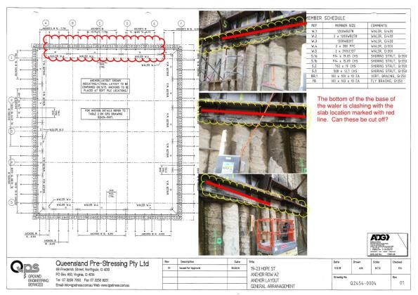
I have another problem, the bottom brackets of my walers clashes with my basement level 5 slab-exactly what we wanted to avoid. So I need to cut the brackets off before I can lay the slab. My sub contractor who designed the waler is not so happy with this idea.
My email below:
There are currently 12 bolts either side of the anchor. If we removed the four bottom bolts this would leave 8 bolts remaining.
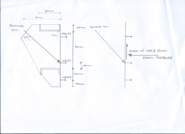
These bolts are AS1252 M30 8.8/s with a shear capacity of 214 KN. Which would leave the bolts with a total shear capacity of 1712 KN not including the friction of steel on concrete. If I look at the anchor summary Q2454-0007 and apply the vertical shear at 45 degrees from the safe working load I get the following:
| Zone | Anchor SWL (KN) | Calculated vertical shear (KN) 45 degrees | Factor of safety |
| 3E | 1244 | 880 | 1.95 |
| 4A | 1316 | 930 | 1.84 |
| 4B | 1280 | 905 | 1.89 |
| 3D | 1160 | 820 | 2.09 |
Even if we factored the SWL by 1.5 this would still be within the capacity of the 8 bolts. Please slap me down if I am being an upstart…
I have since read a paper that indicated the coefficient of steel on dry shotcrete as 0.57, which could potentially reduce my shearing force by 467 KN. Now part of the problem I believe is that the ground anchor does not act through the ‘middle third’ of the waler and so there is a moment induced and the bolts therefore act in tension and shear reducing their capacity. How do I get around this and still cut off the brackets?
I have had a look at the UK’s Steel Bluebook and I think that with the bolts in tension the shear capacity is reduced to 80% – I am having issues looking at Australian Standards at the moment though to confirm what they use here. Any help gratefully received.
The offensive article:![Q2454-0102[A]](https://pewpetblog.com/wp-content/uploads/2016/08/q2454-0102a1.jpg?w=595)
For you Richard:
Arching effect in soils
 Secant wall bending in towards the soil
Those of you that have read my blogs will realise I am having a few issues on site. I have now stopped excavating and have started to build back up. In order to build our stairs we needed to remove an anchor waler. We asked permission from the designers 6 weeks ago, but were ignored. We asked several times more and the designers refused to take our calls. So needing to make progress we sent an ultimatum on Aconex, email and in writing, we would remove the waler on a given date and if they didn’t get back to us then they agreed that it is safe to proceed (for my own sanity I did a free earth model and compared against the wallap analysis for the new case). That date passed and we removed the waler on Friday 19th. The stairs will be built in the next 2 days and will restrain the piles from then.

Ground waler removed from wall so stair can be built.
When I inspected the wall after the waler had been removed I expected movement towards the hole. What I found was the wall had actually moved outwards. The wall is buried in low to medium strength phyllite and this is clearly stiffer than the piles so the ground has arched to the remaining ground anchor walers.
I have regularly inspected the wall and there are no signs of cracking or further deformation. The load has moved elsewhere! If you look at the first photo you will see a slight bow inwards of the shotcrete.
Here comes the science:
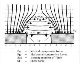
“Arching occurs when there is a difference of the stiffness between the installed structure and the surrounding soil. If the structure is stiffer than the soil then load arches onto the structure. Otherwise, if the structure is less stiff than the soil then load arches away from the structure.
For instance, if part of a rigid support of soil mass yields, the adjoining particles move withrespect to the remainder of the soil mass. This movement is resisted by shearing stresses which reduce the pressure on the yielding portion of the support while increasing the pressure on the adjacent rigid zones. This phenomenon is called the arching effect.”
Self build crane
![IMG_4244[1]](https://pewpetblog.com/wp-content/uploads/2016/08/img_42441.jpg?w=595)
A few weeks ago someone asked how cranes can self build. My neighbouring job is, as I type, building the next level of the crane. The sections of tower are placed on the platform to the left of the tower and the tower is the jacked up so the next section can slide in. You can see one piece about to be slid in and the next on the hook.
![IMG_4245[1]](https://pewpetblog.com/wp-content/uploads/2016/08/img_42451.jpg?w=595)
The first piece has been slid in and the crane is jacking itself up to take the second piece.
I need to have a word with myself because I thought this was cool.
You have to laugh
![IMG_4126[1]](https://pewpetblog.com/wp-content/uploads/2016/08/img_41261.jpg?w=595)
A comedy of errors
In reverse order.
![IMG_4116[1]](https://pewpetblog.com/wp-content/uploads/2016/08/img_41161.jpg?w=595)
Spot the oddity
3. A column orientated in the wrong direction. If you look to the left of the wall you will see a column orientated left to right and not up and down. The bars had to be cut out and drilled 800 mm then grouted in the right direction. See below. Cause lack of supervision and not looking at the drawings.
![IMG_4117[1]](https://pewpetblog.com/wp-content/uploads/2016/08/img_41171.jpg?w=595)
Cutting the bars then redrilling to change orientation.
![IMG_4126[1].JPG](https://pewpetblog.com/wp-content/uploads/2016/08/img_412611.jpg?w=595)
1. The plumber who are sorting the drainage for site were due to backfill around the water tanks with gravel (in top left of photo). They decided to save a buck and used recycled concrete. Not a problem I was on site and when they were dropping it in and although this is not my area, I am responsible for environmental issues, so I asked them for their free from contamination certificate – they didn’t have one. I gave them time to chase it down but they still didn’t have one. We have now had a union walkout for potentially importing asbestos on to site. Cause – lack of supervision and corner cutting by subbie. Solution take a sample then cover in concrete -bung the union 20k. Discuss!
Spot the mistake No 2
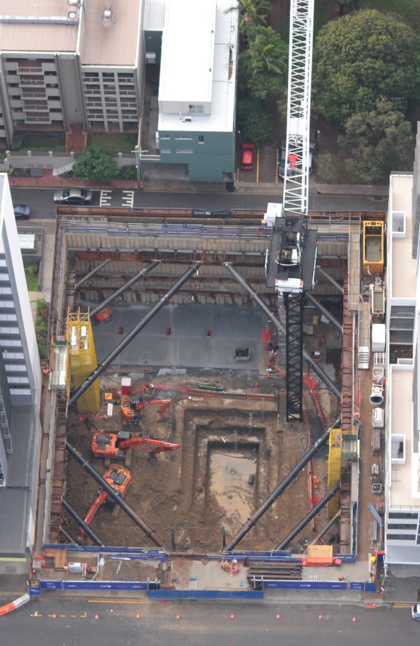
I am beginning to dread Monday mornings!We are just about to backfill the core and are in the middle of a commercial minefield. We have 50% of the footings complete and 30 % of the slab on ground, with the southern half of the site still bare rock and some more excavation to get down to bulk.
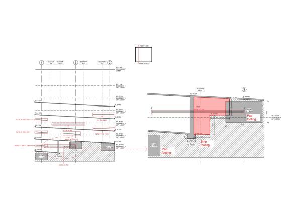
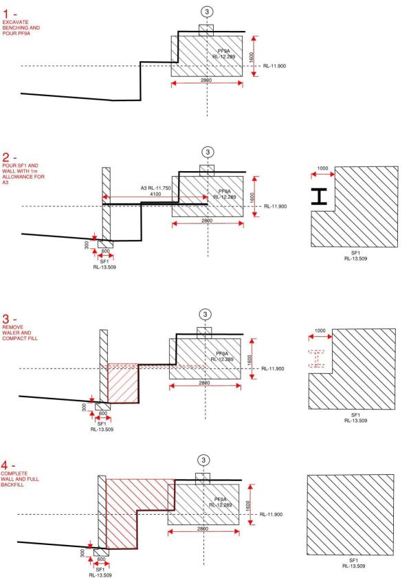
I am dealing with the restraint of the secant pile retaining wall on my site and I was asked to look at a build sequence to remove the anchor waler, that is going through the strip retaining wall. The very helpful wall designers then told me that I had to build the slab above then remove waler. Now this is designed as a slab on ground and the area in red needs to be backfilled. So I challenged that I only had to backfill to the bottom of the waler with compacted fill- They conceded.
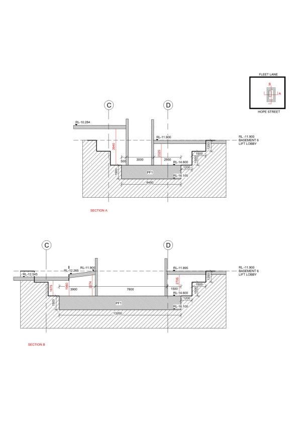
Hurrah – smug for no reason, I go about my business until one of my cadets asks me how the wall is tied into the central core as there are no details of the connections. Now I am not in charge of this wall as it belongs to the ‘lone ranger’ but, he wasn’t interested in what cadet had to say (the cadet is exceptionally bright). I also know this wall is 18 m long and nearly 3 m deep and cannot be supported by the lift core and the secant pile wall. So how is it supported?
Smelling a rat -I check with the Project Engineer who tells me it doesn’t need to tie into the core as it is supported by the slab on top and bottom. What did they miss and how should I solve the problem? I look forward to hearing your suggestions.
Plan view here S-CD-10-001_3-Markup Retention wall

Spot the mistake
The sub-contractor wants to backfill the core (big hole in the picture) with spoil from on site to support the slab on ground that will be locked into the lift core. The core is currently open with 1.5 m benches down the base footing and the backfill will be approximately 3 m deep.
The material is crushed phyllite which has ended up like brown clayey GRAVEL. I needed a CBR of 15 the CBR rating indicates 20, what did I miss. CBR link.
I was talking to the Geotechnical Engineer when I discovered that I am idiot (we already know that my subbie is an idiot). Hint the core is likely to be wet.
Help – I am sorry I haven’t a clue
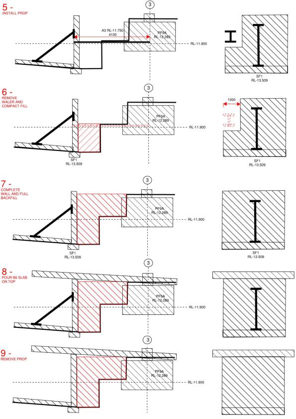
Pride cometh before a fall. I have been working on how to remove the temporary restraints from the secant pile wall for about a fortnight and now I am well and truly stuck. The waler and struts clash with 2 of the slabs. I have deduced 3 possible options, propping off the capping beam with hydraulic props, temporary propping from a lower basement (B3 to B2) and then cantilever the rest of the way, and the third is a hybrid of the two.
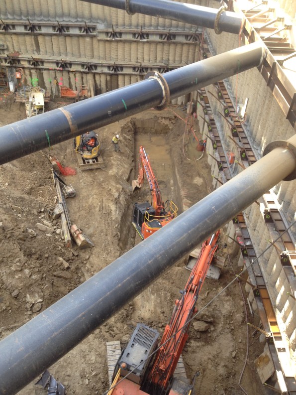
![IMG_2567[1]](https://pewpetblog.com/wp-content/uploads/2016/05/img_25671.jpg?w=595)
Some of the said struts and walers (they are 900 mm in diameter not including splice)
Time is of the essence here and the PM will not accept any loss of time. Which begs the question why didn’t he allow for their removal in the programme? I am naturally prejudiced against the cantilever option as because it slows the removal of the struts and walers by restricting access and I can’t help but ask why the didn’t do this before. The calculated delay to programme is 5 days. With LDs this works out to about $150,000 in lost time. The cost of hiring the temporary props is down to the sub-contractor so this isn’t much of a consideration. Risks – Removal of temp struts and the capacity of the capping beam is not yet known.
Option 2 (propping from B3-B2) is slightly quicker to remove the struts and walers with less temporary works but, it turns out both options require the pour 1 on B2 to be at strength before any struts can be removed so it still works out to a delay of 5 days. However, the wall is deformation is potentially worse and getting the necessary prestress into a diagonal prop can be very problematic.

How the slabs work (numbers denote by pour a slab system is not locked until Pour 1 of the next basement level is at strength). The struts are located between B3 pour 4 and B2 pour 1.
Option 3 (Hybrid) has no delay to the programme but the most amount of temporary works (off critical path) – problem solved right? Wrong my PM has a ‘gut feeling’ and an inspirational idea. Just build over them! This might work if they were designed that way. While I and the Project Engineer were trying to argue for alternatives and pointing out how were we going to remove some of the members that are over 12 tonnes under ground in confined conditions without access to plant, I was being treated to a truly marvellous display of Oxford Union esque debating skills of “yeah I hear what you are saying but what my gut is telling me is if we build over it doesn’t cost me any time”. He then went on to show how we could encaste pulleys in the slab above (fiddling while Rome burned). I am starting to get an idea how this job was was so poorly priced and why it is so far behind programme.
To make matters worse he hasn’t paid Franki Pile who are the design authority for the wall and whose help we need to make this happen. As you can tell my meeting with Franki’s did not go well and I got my arse truly handed to me. While I need to man up and realise tomorrow is another day, other than quick strength concrete to gain the necessary 20 MPa quicker I am pretty much out of options or asking one of our drug dealer neighbours to bust a cap in the PM other than that I am pretty stuck. Do I swallow my pride, log everything and accept it will make a hell of a TMR?
More sketches to follow.
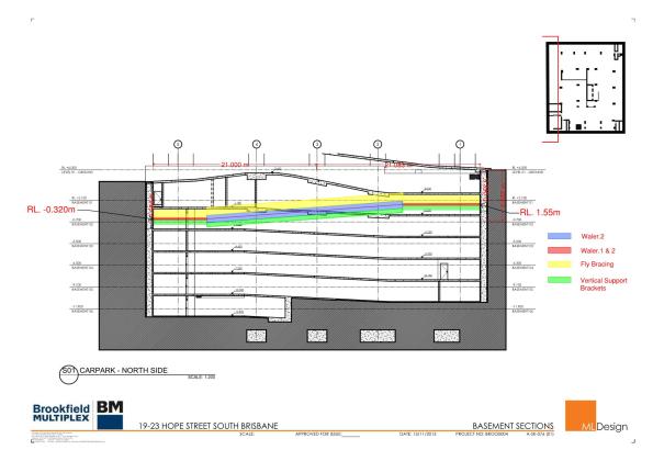
The nature of the problemthe struts cutting though pour 4 basement 2 (B2)and pour 1 basement 1 (B1).

The hashed areas are (temorary props option 2) the struts shown are the existing props. Option 1 would see them replaced by 2 props in each corner off the capping beam.
Breaking Bad Brisbane Style
So its been a hell of week here at Brisbane Casino Towers. The local residents have been high as kites, from throwing objects out of their balconies, jumping on to mobile cranes, breaking into our sub-contractors offices and stealing their laptops and now finally they have been busted for running a meth lab!
 Brisbane’s finest displaying an interesting cordon.
In my last post I mentioned that I have been placed in charge of removing the temporary struts and ground anchors. Believe it or not we don’t have any software for 3 D mapping and given that the problem is a three dimensional one I produced this for my meeting:
Its all hi-tech at Brisbane Casino Towers. (The numbers relate to order of pours and it’s used to explain the load path of the slabs).
The removal of the supports is a nightmare and sums up the project really. The props are designed by ADG, the anchors by QPS, the permanent slabs by BGE and the wall by Franki Pile (now known as the WALLAPs for their worship of the false god WALLAP). For me it is a great opportunity that has drawn the attention of the Regional Director but I can’t help but, feel that they gave it to me because it is something of a mission impossible and they would probably have to sack someone if it goes wrong – (Neil/John TMR2 coming your way). Anyway the meeting went well, I ran it entirely and the 3 chartered engineers were pretty complementary. I will go into more detail later but, this is only the start of it.
Oh on a positive note the we all went to see Australia v England at the Suncorp  I’m sure Izzy is concerned about the English defence and not that I have confiscated the Haribo!
We will rock you
So in my last post I said I would cover a little about working with rock. I am currently excavating in low to medium strength phyllite. Phyllite is a metamorphic mudstone somewhere between slate and schist. It is highly foliated and has fine clay like material in between the layers. The foliation is at 70 degrees to the horizontal across the site. Despite being fairly weathered it is still relatively intact with only a few faults across the site. RQD was between 50-75 % across site. The problem is it weathers so incredibly quickly when wet. I am about 15 m below the water table and water coming through the anchors at about 5 litres per minute. So what I hear you cry – well its rock but it is a galactic pain in the back side to work with.
I am now down at footing level and I am faced with an even worse problem than the bulk excavation. The design has called for individual pad footings which are all at different levels and a core that is 3 m below any of the other pad footings. There are zone of influence clashes everywhere, the architect/structural engineers have very helpfully not included any footing RL so I have had to work them out, as well as how we are going to get the batters and benches in while still being able to move. The geotechnical report states that with low strength phyillite I can achieve a batter of 0.7 H and meduim strength 0.5 H. With H being the height of the batter (not exceeding 3m). So rock strength can be pretty important.Footings Handover Schedule
What strength is that rock? You cannot just take the results of the lab test for Ultimate compressive strength and point load tests. There is a very good website that helps with estimating rock strength via the Rock Mass Rating (RMR) process (RMR rating)that can be then used to calculate the allowable/safe bearing pressure for foundation design. Ultimately though this counts for very little as to get anything signed off you end up with a geotech going mental with a geo hammer on site before telling you its half of the strength you have calculated.
A conversation with the local geotech went along the lines of “how do you come up with the safe bearing pressure do you use RMR.”
“RMR what’s that? Nah, I just use experience, umm what does the drawings say this should be?”
Incidentally I got an RMR of around 45 -50 across the site. That gives between 2880- 1510 KPa am I right?

I made the mistake of being over confident with the bench and ended up having get the geotech back in. In my defence I excavated a pad footing expecting it to be open for the maximum of a week and the PM didn’t make the call on the steel contractors in time so it was open for nearly 3 weeks. The result was water got in and the sides blew out, I had to get the geotech and subbies back in to batter back a ridiculous amount. This all meant time, concrete and money.
There is worse to come – the other Site engineer (little e deliberate)- to be now known as ‘the lone ranger’ took responsibility for the crane base and has massively ‘dropped his baseball’. He wrongly measured the zone of influence of the crane base to the core and failed to gain approval for the design of the pad footing from the geotechs. We are now faced with delaying the tower crane erection or digging the pad footing deeper. It hopefully won’t end up like the crane around the corner though, which has a lovely lean to it. 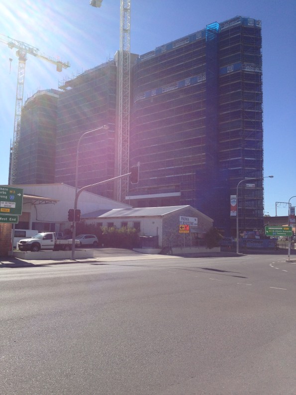
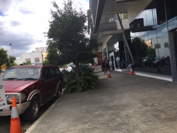
Prima furniture may be getting some renovation work done in the future.
Trouble At Mill
Trouble at Mill
So it has been a while since I have contributed anything. I have been placed I charge of the bulk excavation and installation of rock anchors. Brisbane Casino Towers is now down to Bulk Excavation Level across half of the site and I am supervising the detailed excavation before handing over to the Structural Site ‘engineer’ (the lack of capitals is deliberate). The last 2 months have been somewhat of a rollercoaster and I have learned a great deal from the experience. With the approach of AER 2 it is a good point to review some of the issues that I have had overcome.
Loading Platform
In order to assist with the extraction of soil from the site a loading platform was designed to carry a 47 Tonne excavator. The loading platform was situated on the Hope Street side of the excavation. On 14 April 2016, the braces on the loading platform buckled, halting all loading out of soil and stopping all construction materials from being loaded in. There was a two day delay while engineers could assess the problem and carry out repair work.
The braces buckled due to movement in the secant pile wall that induced a load that exceeded the capacity of the I wrote a TMR on the buckled braces and the stability of the platform down to foundation level. It turns out that at full excavation the wall movement could cause failure and I recommended some alternate tension only restraints back to the secant pile wall as well as a brace back to the loading platform deck to limit the effective length. We held a conference with the designers who were reluctant to admit any wrong doing and just wanted to replace the braces like for like. My PM’s decsion was that we had the sign off from a qualified engineer so it wasnt a problem!
Thankfully the 47 T excavator has now gone and a long reach (33T) has replaced it. The sub-contractor has decide not to risk it (I may have had a word in his ear) so is leaving the excavation high underneath the platform until the platform is removed which has therefore limited the deflection of the retaining wall and the effective length of the plunge columns.
Wallap Analysis. Caution should be used in future projects in the extent to which Wallap analysis can be relied upon for predicting deformations. A safe approach to take is to assume that a wall will deform and design accordingly. Future deformations should be quoted within a range (for example 25-50 mm) to give the appropriate level of understanding to those unfamiliar with geotechnical analysis.
Safety. The Australian approach to safety is similar to the UK’s but different. The Union are seen as the gatekeepers of safety and not the government. Occupational Health and Safety are Australia’s version of version of HSE but they don’t have anything like the powers. Instead Union delegates hold builders to ransom over safety and the approach can seem sporadic at best. BM have a minimal approach to PPE and it is not unusual to see guys laying concrete in board shorts.
 If provoked will strike!
Industrial Relations. Seemingly minor issues are over inflated to put pressure on the state and national governments or employers. The Union effects almost everything in the construction industry and sub-contractors can be blackballed and banned from site even if they have gone through a comprehensive tender process. Walk-outs are common and safety/welfare incidents can be orchestrated to give the pretence for a walk out. To make matters worse if workers down tool for safety reasons they are entitled to a full day’s pay and can even be paid to leave site for a 2hr meeting/march. My site is only around the corner from the Union Headquarters so workers are typically called in for rent a mob demonstrations. It is so bad that you cannot even use the word ‘union’ in correspondence. I had a walk out on site relating to cracks in the secant pile wall when I was drilling the first row of ground anchors. Despite displaying the monitoring results and analysis of the wall the Union delegate held the company over a barrel making various demands before allowing the boys back to work. As a consequence our survey budget has been blown out of the water monitoring wall deflections daily. The only consolation I have is that as bad as they are here they are even worse in Melbourne – you have my sympathy Jo.
![IMG_2697[1]](https://pewpetblog.com/wp-content/uploads/2016/05/img_26971.jpg?w=351&h=468)
First footing in and boom the steel budget gone
Budget. Money is really to tight to mention on this job. BM bought the work from the client in the hope of becoming the preferred contractor. As such we are trying to cut costs all over the place. The decision has been made not to pour blinder and we are laying the footing straight onto the phyllite rock. Incredibly BM have run out of money for steel after our first footing. At tender the consulting engineer estimated 50 Kg/m3 as opposed to the 80-100 Kg/m3. We have blown that in the first mammoth pad footing. Another Brisbane Casino Towers budgeting classic. We are debating the merits of back charging the consultant as we speak.
Pile Tolerance. The secant pile wall is the permanent solution for the retaining wall. At a depth 18 m the worst offending piles are off by approximately 200 mm and need to be ‘scabbled’ back in order to fit the ground anchor walers on. This causes an issue as the cover is supposed to be only 150 mm, so far we have not hit steel and I am beginning to wonder if they are reinforced! The piling contractor (Franki) actually haven’t done a bad job as out of the 264 piles on the job only 8 are problem children. I have been told by the Franki that you would be unlikely to see this type of wall beyond 6 m in depth in Europe.
Programme. We are currently 10 days behind programme and Delta are due to pay $15,000 a day for every day they delay the basement handover. So this could be quite expensive for them. BM are less interested in pursuing the Liquidated Damages (LD) are more interested in getting the time back as BM’s LDs to the client for delayed completion are nearly 3 times that. So why did these companies agree to the LDs, well they are part of how business gets done down under and are routinely incorporated into every contract. Normally the LDs are not pursued because there is a small construction community but given the tight budget that BM are operating under they have very little choice.
I have probably written enough for one post but I will follow up with another article on rock anchors and engineering in rock.
Rich/Dam0
PSB![IMG_2714[1]](https://pewpetblog.com/wp-content/uploads/2016/05/img_27141.jpg?w=595)
Calcs are indicative only!! (The brace is 6 m long)
