Archive
It’s not all about the bike…
I’m currently reflecting on the last 15 months living and working in Oz whilst exploring the vast bush of WA.
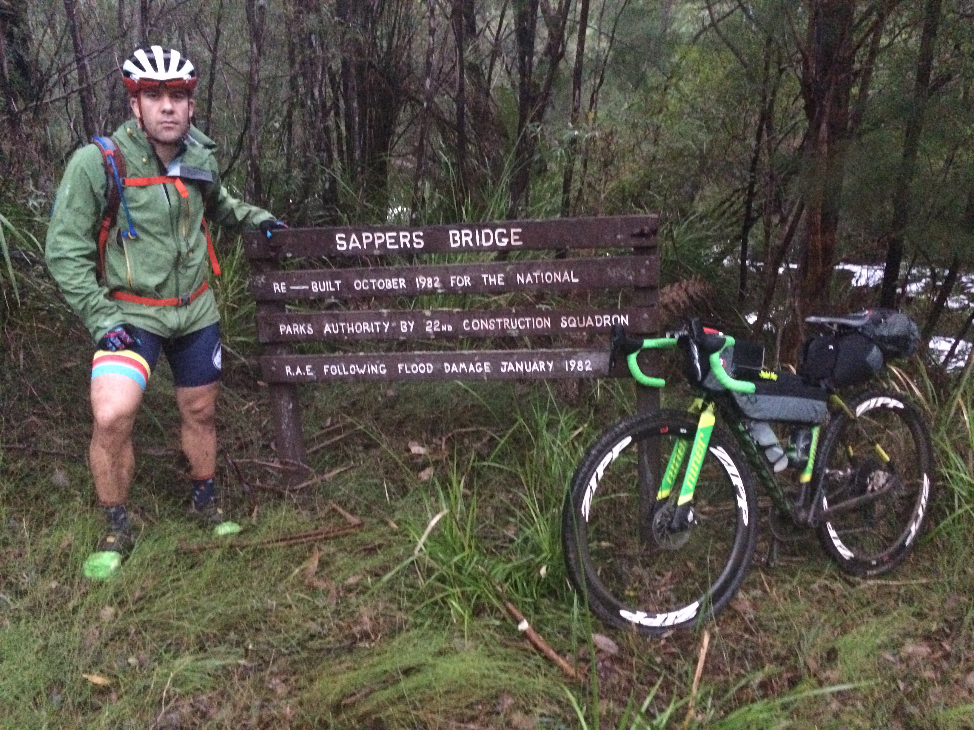
I’m about to start day three of a 10 day epic trail ride from Albany back to Perth following the infamous 1000km Munda Biddi trail.
So far the terrain is akin to the UK’s green rolling countryside complete with similar weather – very wet and windy!
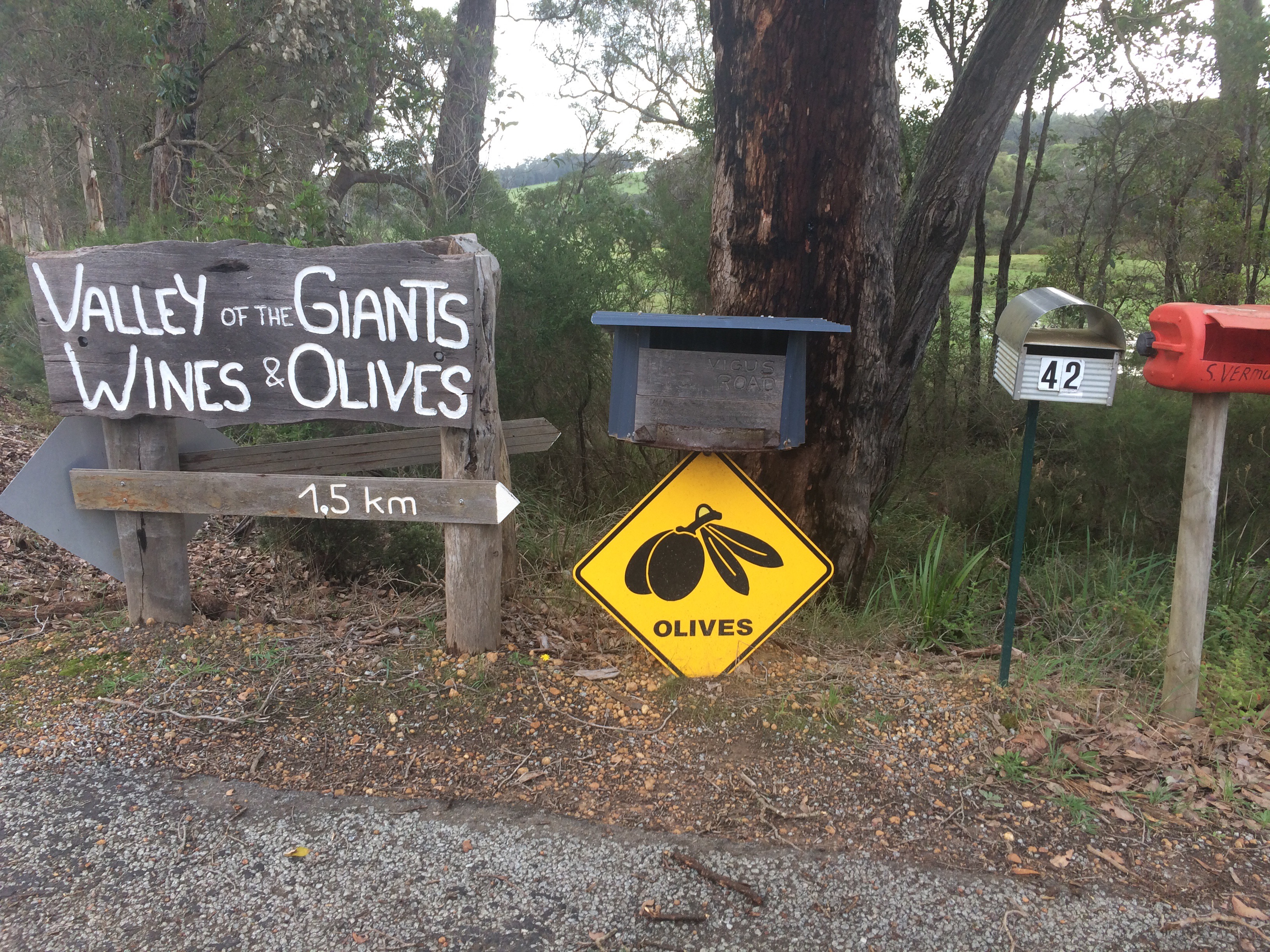
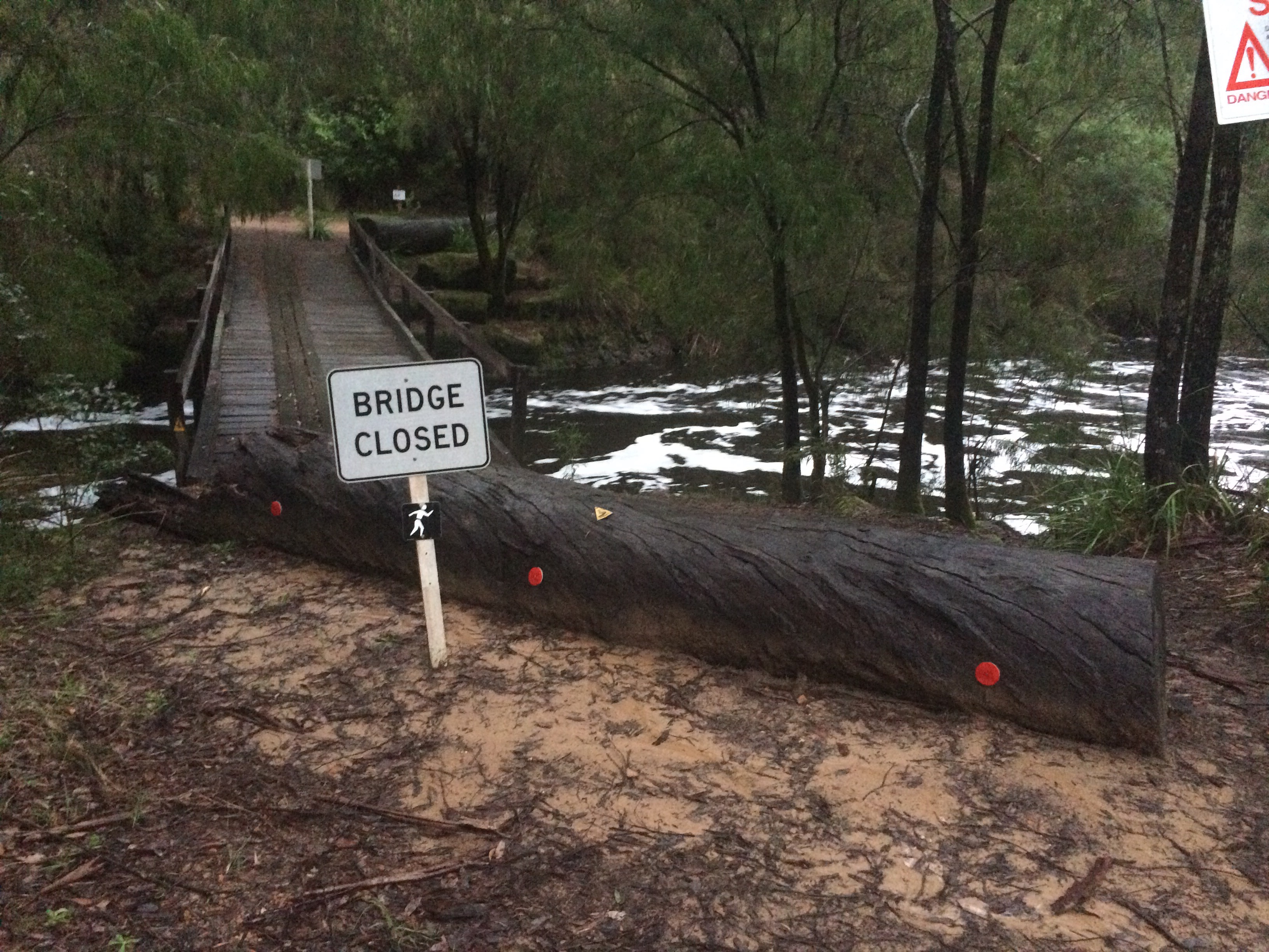
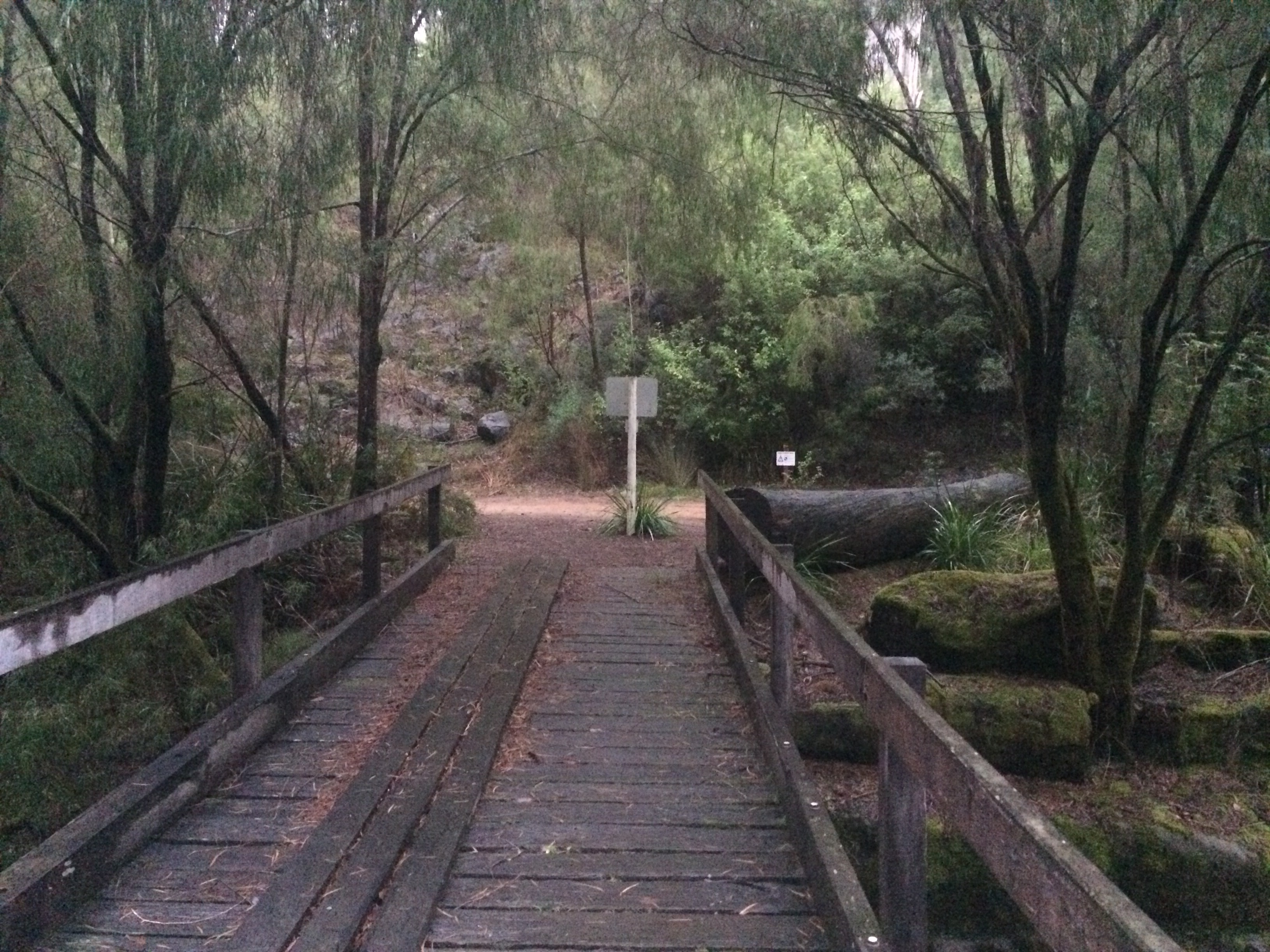
En route I have come across the more obscure Aussie road signs and Sappers Bridge.
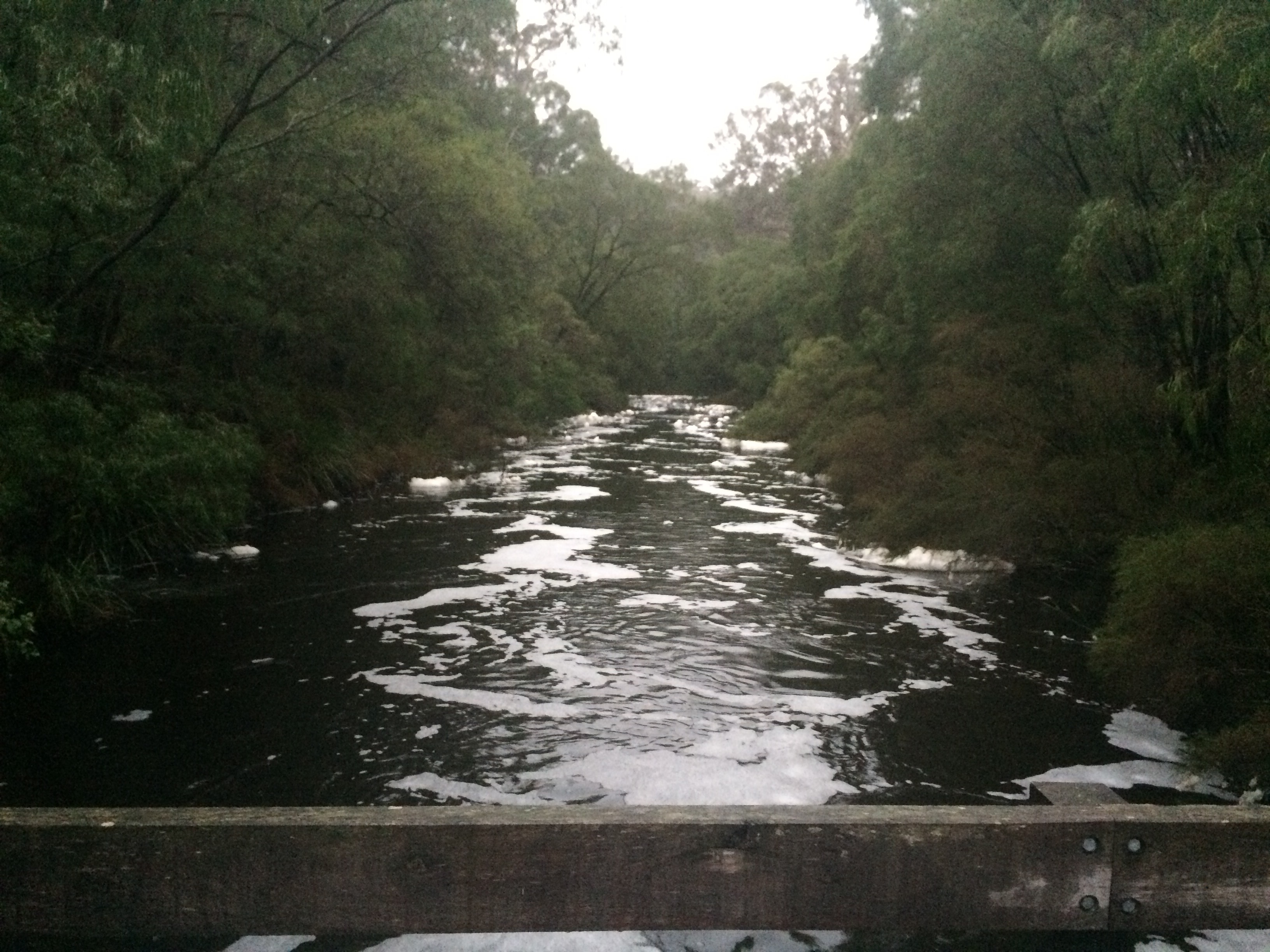
220km down with a couple of easier days ahead before the epic 167km day 5!
Oz PCH – Subbies not getting paid…never!
I saw this in this week’s The Western Australian and thought it worth a share…
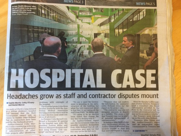

If the print is too small to read is summaries that JHG are submitting false statutory payment declarations to the State Government of WA (the client). This particular subbie is owed $335k for works completed and there are others who also claim they are owed for work but are reluctant to speak out while they hope their disputes can still be resolved.
There is also talk about the façade subbie, Yuanda who are reported to be owed $12 million. However, this is due to a dispute over a number of faulty/damaged panels. I think JHG are worried that the cost involved of replacing so many panels is not worth what Yuanda would stem to lose and so fear they would just walk away and not bother – hence JHG withholding payment – which we all know, to use Australian slang, is just not cricket.
The devil will be in the detail and the report goes on to say that the Auditor-General’s review found JHG had presented “reasonable” grounds why amounts claimed by subcontractors had not been paid.
Oz NDY – IMechE CEng CPR Application Issues – Forewarned is Forearmed

This blog highlights some issues experienced of the IMechE CEng Chartered Professional Review Application process and previous academic review documentation. It also discusses hints and tips on CPR submission.
The main issue seems to stem back to the initial academic review submission that is required if your first degree is not accredited by the IMechE. I submitted my academic review back in 2012, at which time I wasn’t really clued-up on the whole chartership process. It is possible other E&M students on Ph2 might have had to do the same and could unknowingly be in a similar situation I found myself in. If so or unsure, now is the time to check and avoid it being a surprise and slight embuggerance if something needs to be submitted short notice.
The Issue
When you submit you CEng CPR application, more on that below, someone from the membership team will review it alongside your previously submitted academic review. One question on your academic review asks what level of registration you want to be assessed against. Make sure you have ticked the box for either CEng or Both. I ticked IEng only, thinking I would be awarded IEng form that point onward not realising that I would also need to submit CPR evidence and sit an interview at that stage. This was something I wasn’t planning on, thinking that I’d just wait until I had completed the MSc and simply submit CEng CPR evidence then (as I have done).
This sparked the notification that the IMechE can’t assess you for CEng if you haven’t ticked that CEng box (or Both) on the academic review. I’m still not entirely sure why, especially after explaining that nothing has changed from the initial academic review (which has IEng ticked) to the latest one I have had to submit (which has CEng ticked). Just seems like a whole lot of wasted time and effort due to a tick in the wrong box, but the process is the process and clearly some other internal shenanigans that can’t be messed with.
As for the CEng CPR application this is relatively straight forward but there are a few hints and tips I’d like to share to make it that bit smoother for when others come to do it:
- The IMechE website isn’t the most intuitive to navigate so use the link below to the application process.https://www.imeche.org/membership-registration/become-a-member/chartered-engineer/application-guidance
- Download the PDF doc and fill that in with the ability to easily edit and see what it looks like in the form.
- Download the exemplar as a guide or ask one of my cohort for a copy of theirs.
- Irrespective if you have used the PDF form or not you will still need to complete and submit the on-line form as this is linked to the application payment method. Once complete you can download a PDF of that on-line submission.
- I found it best to initially write in a word doc then copy and paste across – that way you can ensure you are within the word count, which although they say ‘approximately/around 400 words’ for each competence, they actually mean ‘no more than’ as some sections won’t let you progress if over the limit.
- The PDF form asks for signatures of your two sponsors yet the on-line form just asks you to confirm (via tick of a box) that they have read a copy of your application before you actually send it – so no need to actually get the PDF copy signed. IMechE send an email out to your sponsors anyway with a ‘no action’ verification statement.
- The on-line form initially asks you to complete your personal details prior to the competences sections. This is easiest entered prior to completing the form by going through the My Profile in Your Account. Of particular note is ensuring you enter phone numbers under the Personal and Work tabs, even though the work tab phone numbers are not *stared. I just added SI PET’s for the direct dial landline – but I’d like to think they’d call you on your personal phone first. Without these numbers entered the form seems to stop you continuing to the next section when completing on-line.
- There may be some other glitches I haven’t come across so anyone else who’s submitted forms feel free to comment.
Oz NDY – Mirror, Mirror on the Wall…
This blog discusses a couple of examples of key reflections I have made based of my own actions and decisions on the Perth Children’s Hospital (PCH) project and the Vetwest Animal Hospital project. One describes aspects that went well and the other, although an overall successful project, describes simple mistakes that were made. My overall view is that it actually doesn’t matter if something goes completely ‘pear shaped’ (not that anything has) as long as there are learning points that can be realised, whether through self-critique (reflection) or identified through a more formal feedback process. The key importance to the reflection piece is that once outcomes are reviewed, the point of failure identified and then communicated to those parties involved, it is only then possible to go about seeking ways to implement improvements so they don’t happen again.
PCH – Safety Critical Testing
During Ph2 on the Perth Children’s Hospital (PCH) project I conducted a piece of work involving the tender selection process and procurement of a small works package to conduct safety critical testing. The specifics of this can be found from a previous blog, link below.
https://htstrial.wordpress.com/2015/11/27/oz-pch-commercial-and-contractual-tasks/
In summary, JHG had conducted a theoretical study on the suitability of a number of EEG (brain scan) recording rooms to resist RF/EMF interference from various building sources, internal and external. A further stipulation of the requirement was to test for interference concurrently with a live EEG test being underway. The outcome of this study was that although RF specialists, Faraday, suggested additional screening was indeed required in some locations, JHG decided to value engineer out of the programme the works associated to. Aiding JHG’s decision were EEG equipment vendors who made recommendations that was contrary evidence to Faraday’s findings. This is why the client, not wishing to take any chances on medical examinations, stipulated that practical testing be carried out to confirm if screening was required or not.
I conducted a fair amount of research into the requirement and wrote the scope of works used to go to tender. The important reflection piece was getting the detail of the scope of works right and the decision to include Faraday as a tender nominee. This was so that politically and from a presentational point of view, as they were still contracted on the project under another works package, it would have been unjust to exclude them. However, my view was that we needed to remain cautious due to their position, noting that their theoretical study suggested additional shielding was required and I didn’t want that to somehow influence their testing if selected. That’s because the upshot of the results would have huge commercial implications given that all the EEG recording rooms in question were completed and to add more shielding would require a costly strip-out and re-build, no-doubt including other knock-on issues and more cost.
When I left JHG (Nov 15) the tender selection was complete, bar the confirmation interview, and so it was just a case of waiting for the testing conditions to be co-ordinated and ready to start testing. On my recent visit to site accompanying the CI, the building services manager, my old line manager, informed me of the outcome of the testing. There were a few minor interferences from external systems into some of the rooms; these walls now need to be lined with extra shielding. However, worse still when the live EEG recording was underway there all rooms showed massive interference from something inside the rooms. This has now sparked a new investigation to establish the cause and resolve it. The other key reflection point here is that I made sure in the cost break down section of the works included subsequent rounds of testing should the initial results indicate a failure. This was why we selected EMC Services as the preferred specialist consultants as they were the cheapest over all three rounds of testing (the maximum required) and didn’t charge for additional provision of reports.
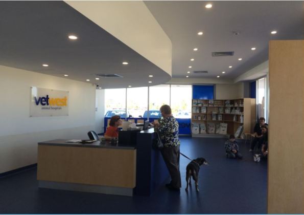
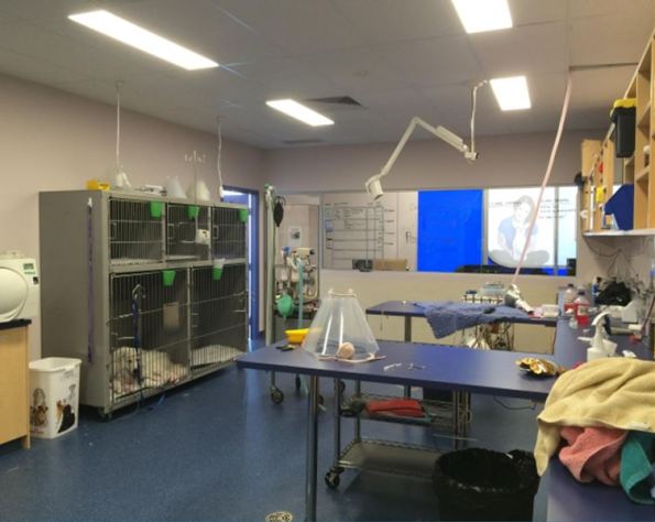
NDY – Vetwest Animal Hospital
Like the first example I have already discussed my involvement in my first project leader role on the Vetwest Animal Hospital project, see link below.
https://wordpress.com/post/htstrial.wordpress.com/11190
Now complete I conducted a feedback session on site with the construction managing contractor, Perth Citi Fitout (PCF). The reasons I wanted to do this were threefold: understand what went right, wrong or what could have gone better in order to improve where needed for the two subsequent projects that I was informed we’d most likely win; allow me to properly reflect on my first project leader role for self-appraisal; and finally to retain any lessons learnt to ensure corporate knowledge is not lost when I leave.
Overall the project was a success, testament being a number of conversations with PCF’s managing director who has praised my work and co-ordination of project leading and is looking to conduct two further Vetwest projects with NDY as the design consultants.
The biggest issue, which wasn’t really that big a deal and which was easily resolved and done so promptly, was the missed deconfliction between the supply air diffusers and light fittings. Although the lights themselves were not included in the scope of works we did have the CAD file of the ceiling plan. It wasn’t until the lighting sub-contractor began installing the lights did it become apparent that the diffusers were already installed and in some but not all cases they were where the lights should have gone. A phone call to me explaining the issue was enough to quickly go about resolving the issue. This was a chat to the CAD department requesting that the electrical ceiling layout and mechanical layout be deconflicted. There were a few knock-on effects, mostly being a number of supply air grilles that required blanking plates to avoid cold air hitting and dumping down wall surfaces in some of the smaller consulting rooms where it would be noticeable; also, the time to source and fit them. One unaffected outcome was that moving the diffusers by a ceiling tile or two was practically very simple as mech sub-contractors love to use flexible ducting running off the indoor units and they always allow a metre or so spare capacity.
The reason this issue slipped through the net was due to me making an assumption that the CAD draughty would have done this check when overlaying the various discipline layers in Revit – lesson learnt, don’t assume, ask and get confirmation.
Other smaller issues were some of the technical specifications of fixtures and furnishing were the incorrect type, for example, the back of house laundry sink didn’t fit in the cabinet as it was too deep and the sensor activated scrub sink taps were apparently the wrong type. This was again a case of not checking that the tech spec brochures provided were correct, although you could argue that this should have been a check conducted by the managing contractor when they were reviewing the design drawings. Another issue, from an aesthetic point of view, was the medical oxygen supply pipe running from the cylinder cage outside to inside was installed running up the inside of the wall from ground level to through the suspended ceiling. The core through the outer brick wall should have been located in the ceiling void and the pipe run down the outside of the wall where no one will see it. Having chatted this through with the hydraulic design engineer he said he accidently omitted the pipe dropper symbol on the CAD dwg and so the hydraulic sub-contractor literally followed the dwg – which I suppose you can’t blame him for but maybe he might have seen this type of arrangement before and should have least had a chat to the on-site PM.
As part of the same feedback session I also had the opportunity to ask questions of the clinic team manager, as Vetwest were moved in and the practice was in full swing. Astonishingly, none of the staff were consulted by the Vetwest project manager. She was shocked when I told her that this level of stakeholder management was an absolute must and should have been conducted. It transpired that on her initial induction walk round her and her staff pointed out a number of incorrectly located equipment including the unnecessary installation of a hose cock tap and floor waste bucket trap for the Cattery. Their SOPs are to simply sweep out. There was also the requirement to fit an extra oxygen pipe branch into the X-Ray room. This was something I recall having a telephone conversation about with the Vetwest project manager and remember getting it confirmed in writing. It was to be included then it wasn’t then obviously it was. The issue with it was that the terminal out the wall was in the wrong location for their trolley to connect onto and reach the dog/cat when positioned on the X-Ray machine.
A lot of this is down to a lack of internal Vetwest stakeholder engagement and is a valuable lesson learnt.
What Now?
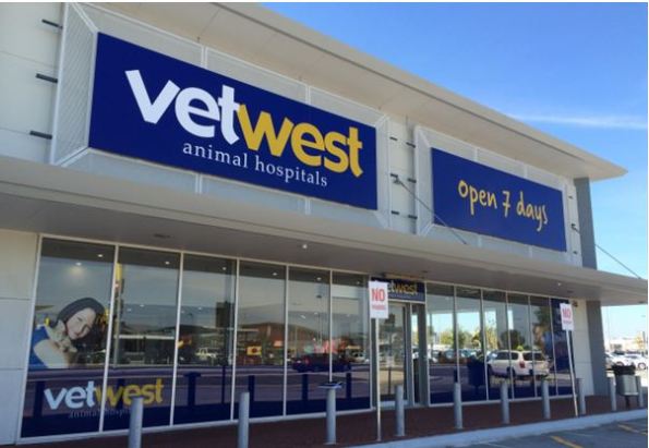
Having conducted the feedback session I am presenting these findings to the design team involved in the project and therefore closing the loop on the continuous improvement process. It also highlights the issues mentioned above and aims to ensure that whoever project leads the next two projects, they understand where to find particular information. An example being: the Australian Veterinary Association Accreditation Scheme that Vetwest was seeking to highlight to their customer base and regulatory inspectors of their attainment of best practice animal care. I achieved this through understanding the technical implications of accreditation, like ensuring cleanliness standards are as high as possible. To strive for best practice here meant installing HEPA filtration in the Surgery room.
From this….
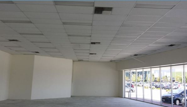
…to this.

In Other News
We’ve seen a fair amount of aquatic life, and swimming with Whale Sharks was definitely one of the highlights of our time out here.

Oz NDY – CPD Activities
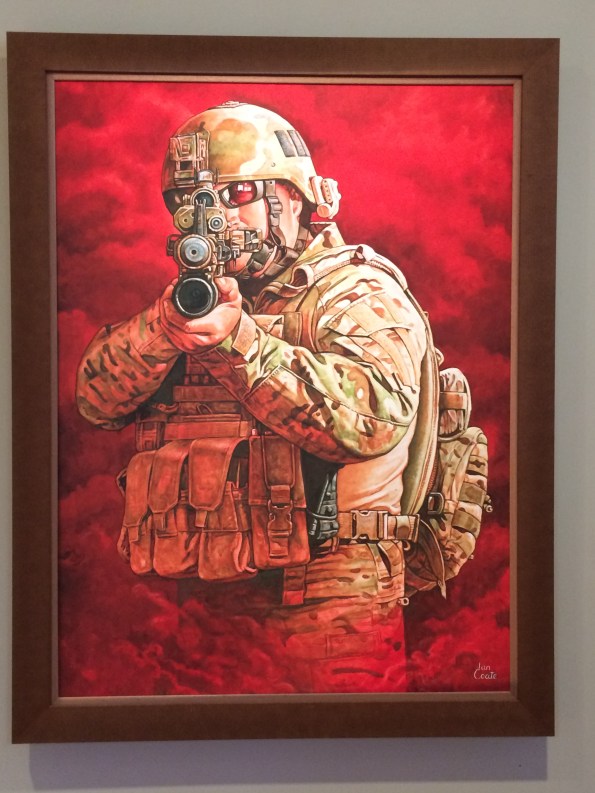
Australian SAS Operator
Introduction
In similar fashion to the comments on Riche’s latest CPD blog, I too have been hunting out more formalised CPD activity opportunities. Although there are some within the design office I wanted to broaden my search and so started looking for opportunities outside of the workplace. Namely seminars, conferences and workshops delivered by professionals in the building services sector and that are affiliated to various engineering institutions.
This blog briefly discusses a seminar I attended hosted by Lighting Options Australia as part of the Society of Building Services Engineers WA Chapter in association with CIBSE.
Lighting Options Presentation
The seminar consisted of the usual finger food and drinks reception, with a studio tour followed by a technical presentation on LEDs in 2016, which culminated in a Q & A session.
The speaker, co-founder and MD of Lighting Options Australia has been involved in lighting throughout his 17 year working career, combining on-the-job experience and knowledge whilst working in partnership with several internationally renowned lighting brands.
Before the presentation kicked-off the speaker demonstrated some of the lighting options used in their showroom gallery. One painting of interest was the Australian SAS Operator, which was painted by an ex-serviceman’s wife. It is said that whichever angle you look at it from, it always looks as though he is aiming directly at you.
The presentation covered three areas:
- LED performance in 2016.
- LED/Luminaire life and lumen maintenance.
- Introduction to Richard Kelly’s ‘Language of Light’.
Presentation Summary
- LED performance in 2016. Four factors were discussed: efficacy, colour tolerance, colour rendering index and failure rate.
- Efficacy. Luminous Efficacy is the measure of how well a light source produces visible light (to the naked eye). It is the lumen value against the energy consumption, measured in Lm/W. Manufacturers usually display this technical data along with the colour temperature, measured in Kelvin (K). For example, 100 Lm/W (3000K) or 130 Lm/W (4000K). The colour temperature describes the impact of colour, which gives either a warm light (<4000K) or a cold light (>4000K).
- Colour Tolerance. This is the colour consistency amongst exact same light sources, for example, an array of lights along an art gallery wall, where a higher colour variance in one source could be very noticeable and detract from the required lighting effect. There is a standard/tolerance for the acceptable degree of variation in colour temperature, ANSI specification C78.377-2008. The tolerances can be identified by applying the MacAdam Ellipses. The size of the ellipses is based on the standard variance called ‘steps’, the more steps the higher the variance and more obvious to the naked eye (see figure 1).
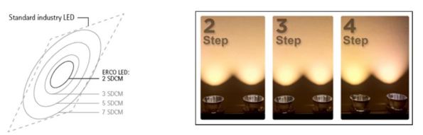
Figure 1. Colour Tolerance measured in MacAdam Steps
With the innovation of LEDs moving lighting technology away from the more traditional incandescent or compact fluorescent light sources, it introduces more variables where the Correlated Colour Temperature (CCT) of LEDs is liable to move further away from the target colour. Typically, incandescent and fluorescent ellipses don’t exceed 7 steps. Therefore, due to the easier identified colour variance, the LED standard states that CCTs must be within 4 steps MacAdam. The following link explains colour tolerance in more detail and is the source of reference.
http://www.lampslighting.co.uk/colour-tolerances/
- Colour Rendering Index. Colour rendering measures the light source’s ability to render colours correctly and is graded from 0-100. The old standard was to use eight colours to act as the controls against a pre-defined light source. This has now been increased to a 99 colour sample (see figure 2). The new sample range is more representative of real-world objects as opposed to the original and is intended to fairly and accurately characterise LED and legacy light sources.
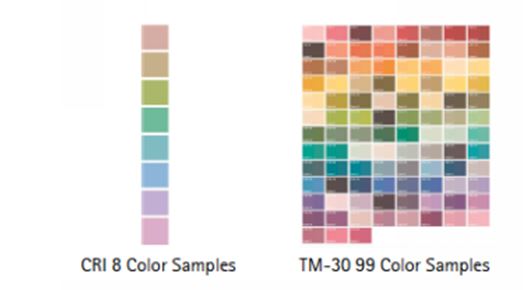
Figure 2. Colour Rendering Index.
Failure Rate. When conducting lighting design and planning off failure rates it is important to understand that traditional, incandescent and fluorescent, light sources are failure rated at 50% over their rated life, which indicate that the lamp has failed to the point of needing replacement. However, the standard failure rate in the LED market is 0.2% for 1,000hrs. That works out as 10% after 50,000hrs (the standard LED manufacturer specification failure rate which is extrapolated from an industry accepted standard of 8,000hrs burn time). The latest in LED technology, as manufactured by ERCO, has decreased this by 100 times to <0.1% for 50,000hrs. By example this means if using 100 x 10 LED chip luminaires in a project then only one single LED out of 1000 might fail after 50,000hrs.
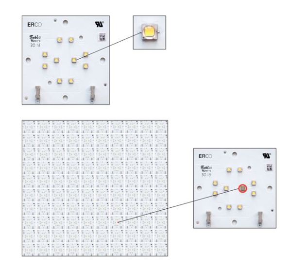
Figure 3. ERCO LED Failure Rate
2. LED/Luminaire life and lumen maintenance.
This part of the presentation discussed the characteristics that determine LED life and maintenance. There are four values:
- L – This is the light output of a LED module which decreases over its lifetime. L70 means the LED module will give 70% of its initial luminous flux. This value is always related to the number of operation testing hours (usually 8,000) and therefore is a statistical value so a batch of LED modules may have a slight variance in their lumen maintenance. A point to note is manufacturers should state the testing hours of their product as some try and mislead their customers by only testing to 4,000hrs. This means there is likely to be a higher percentage of error when extrapolating to the 50,000hrs rated life but they clearly do this as it halves their testing time to approx. 5.5 months thus cheaper to produce and get to market. If a product doesn’t say it’s testing hours it is safe to assume it is 4,000 and not 8,000hrs
- B – This is the degradation value of LED modules which are below the specific L values. So, L70 B10 means 10% of the LED modules are below 70% of the initial luminous flux.
- C – This is the value of fatal LED module failures, indicating the percentage of modules that will actually fail.
- F – This is the combination of B and C values, for example, L70 F10 means 10% of the LED modules may fail or be below 70% of the initial luminous flux. As a rule of thumb the most commonly used values are L and B. The LED market standard specification currently used is L70 B50 (50,000hrs), e.g. after 50,000hrs only 50% of the LEDs used still achieve 70% of their original luminous flux. ERCO uses LEDs with the specification L80 B10 (50,000hrs), e.g. after 50,000hrs at least 90% of the LEDs still active achieve 80% of their original luminous flux. Figure 4 shows the two graphs for comparison.
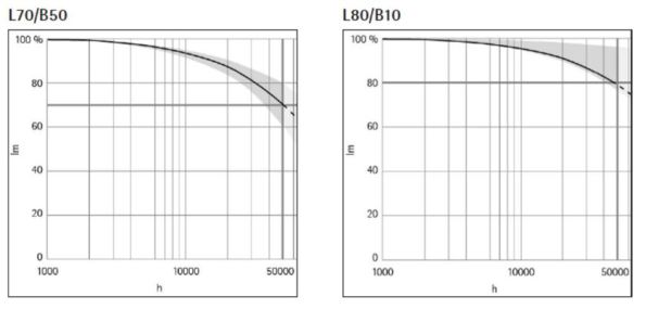
Figure 4. Traditional Vs ERCO LED Specification Maintenance/Failure Rate
Here’s the difference in a real life example:
There are 10 x LED downlights used to achieve an average 500 lx and rated at L70 B50 (50,000hrs).
At 50,000hrs – 500 lx x 0.7 = 350 lx
At 50,000hrs – 350 lx x 0.5 (worst case) = 175 lx
The same 10 x LED downlights are used to achieve an average 500 lx but this time rated at L80 B10 (50,000hrs).
At 50,000hrs – 500 lx x 0.8 = 400 lx
At 50,000hrs – 400 lx x 0.9 (worst case) = 360 lx
So you can see using the L80 B10 specification retains 72% of the original lux level after 50,000hrs versus just 35% if using L70 B50.
3. Introduction to Richard Kelly’s ‘Language of Light’. The final part talked about the American lighting designer, Richard Kelly, who was said to have been one of the pioneers in architectural lighting design. One of his goals was to be able to get both architects and lighting design engineers to speak the same ‘language of light’. To achieve this he came up with a very basic concept that broke light down in to three simple elements:
- Ambient – ‘Ambient luminescence’ is the element of light that provides general illumination, ensuring the surrounding space, its objects and any people in it are visible. This form of lighting facilitates general orientation and activity. Ambient luminescence is the foundation for a more comprehensive lighting design and aims to have differentiated lighting that builds upon base layers of ambient light.

Ambient
2. Accent – ‘Focal glow’ is the light that helps to convey information and guide movement. Brightly lit areas automatically draw our attention. Directed light accentuates focal points and helps to establish a hierarchy of perception using brightness and contrast, helping to emphasis important areas and accelerate spatial orientation.
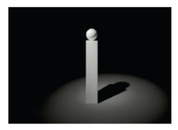
Accent
3. Scenic – ‘Play of brilliants’ results from the ability of light to represent information in and of itself. It covers a multitude of lighting effects used for their own sake, for atmospheric or decorative reasons, but having no specific practical function. Examples include, an emotive candle on a table, a fire place, an object of coloured light being used to influence the ‘climate’ of a space.

Scenic
Examples of all three elements combined can be seen in the following photos:
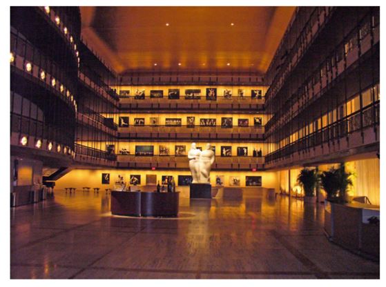
The State Theatre, New York
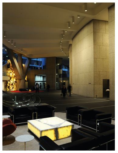
Grovsvenor Place, Sydney
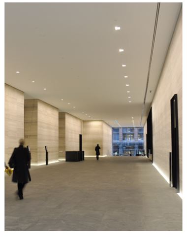
171 Collins Street, Melbourne
Forthcoming Events
Having chatted to the CIBSE Fellow who organised the event I am now in his ‘in-tray’ for any upcoming events which he assured me are roughly one per month covering various building services topics.
Oz NDY – Return Air Plenum Issues – Part 2
Following a site mtg we have a much clearer understanding of the issue at hand. The mech contractor, Envar, have sent us a mark-up (as requested) of the location and sizes of all holes made by the builder to initially increase air flow; which it has.
So why are we not getting the correct RA flow to the AHU? It also came to light that there is heavy congestion (as shown in fig 1) around a services (namely ducting) choke point (about 1 m2) which is restricting the RA flow. The congestion issue is unique to this level due to the balcony which a severely reduced the overall free area by approx. 1 m2. So, in theory we could turn the closest partition wall into a sieve and we would still have the problem. We can’t practically do this though as there isn’t enough space in this particular partition.
Therefore, we still need to get the balance of air from somewhere which the AHU fan is drawing in. So with the choke point in mind this will have to come from the SA side (the corridor) outside the plantroom. This corridor is open to the large open-plan office area but air flow either end is stopped by pneumatic actuated doors (for security as these areas are sub-tenanted). So what? The makeup air would be mostly SA and not RA as intended. So how does this affect the CO2 levels?
Below I’ve recalculated the area of hole required which would be incorporate as either a door grille in the plantroom door, or, depending on size, it could turn out to be a complete louvered door.
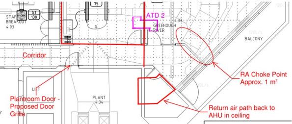
Figure 1. Return Air Choke Point in Plenum.
Calculations
A quick calculation to check the hole size required:
Q = 8.839 m3/s. This is the entire SA flow rate that is trying to get back to the AHU as RA.
A = 1 m2. The approx. area of free flow through the choke point.
Therefore, V = 8.8 m/s. That’s pretty quick and why it has also been reported that a few ceiling titles are flapping around near the exit hole from plenum into plantroom. These are being addressed by replacing with egg crate extract grilles.
If we want to achieve a steady flow rate of 5 m/s then this gives an A = 1.77 m2. Subtract from that the area we do have (1 m2) = 0.77 m2 hole required.
On a basic 2100 x 920mm door (leaving an edge of 100mm both sides) gives a door grille neck dimension requirement of 1100 x 720mm = 0.79 m2. That’s the ‘free air’ area needed where a louver or grille would require being 50 – 60% bigger to take into account the area lost due to the vanes. So, it would need to be 1.26m2, which is about 1800 x 720 = 1.29 m2 which equates to pretty much the entire door when you take into account the structural edges.
So what? It would require attenuation on the plant side of the door to mitigate plant noises transferring back into the corridor, which shouldn’t be heard too much anyway as it is just a corridor and the open-plan office area is actually through a central kitchen/restroom area.
To check this I spoke to our acoustic engineer and used the dB data. The corridor was reading 52 dB, I then added 25 dB for removal of the current door and then subtracted 5 dB for adding a louvered door with some attenuation on the reverse side. This results in 72 dB being heard in the corridor, which is about 22 dB over what it should be (50 dB being the norm). Therefore, this is a problem and exacerbated by the frequency range of the particular plant, which will be a low rumbling (low freq) which louvers still let through.
It would therefore be better to install an ATD above the plantroom door but this idea was discarded due to a large duct run right next to it running down the length of the corridor. This also means that we can’t put any more egg crate extract grilles in as the one currently installed sits no more than 10mm below the ductwork so this too will be restricting the RA.
The only other option I can see is putting in a large or two smaller ATDs through the wall area into the plantroom. But even this has its issues: is there free space on the other side of the wall? How far away is the AHU and can we fit a ATD in? Being the base build, will the building owner approve it?
I have also been informed the AHU has an economy cycle (which I should have expected) where the ambient OA temp dictates how much OA is used rather than wasting energy in cooling RA when there’s ‘free’ cool air available from outside.
ATDs
I made a point of mentioning the need for ATDs in the cut-outs. With the extra holes present no occupants have complained of cross-talk, therefore Envar suggested they would get the builder to tidy-up the holes and leave them at that. Ironically, it seems like any holes made in the partition wall don’t need attenuating due to the ductwork congestion.
Oz NDY – Return Air Plenum Issues
Introduction
Prior to Christmas I was given an interim task to investigate complaints of doors being hard to close with loud whistling noises coming from the plantroom door on level 4. The project is a typical tenancy office fitout with construction complete and the office space occupied by Synergy staff.
I was given an initial steer by the project leader; his view being restricted Return Air (RA) flow to the AHU.
Background
The design of the floor (slab to slab) uses the ceiling void as a large RA plenum. The plantroom, containing the AHU, acts as a large mixing chamber mixing the RA (from the plenum) with the Outside Air (OA), which enters through louvers in the skin of the building. It incorporates a CO2 monitoring system that controls the motorised louvers to alter the amount of OA required to keep CO2 levels within permissible limits.
The main floor space is split up in to a number of offices (various sizes) and larger open plan areas. To reduce the chance of cross-talk between these areas full-height partition walls were constructed. Whilst this met the acoustic requirements it created a subsequent problem; the RA was being severely restricted in its attempt to get back to the AHU.
To resolve this, the design incorporated the use of Air Transfer Ducts (ATDs) installed through the partition wall. ATDs are essentially fitted into a rectangular cut-out in the wall and consists of standard metal ductwork lined with acoustic material. This allows both air flow through it and simultaneously reduces carried sound, as shown in figures 1 and 2.
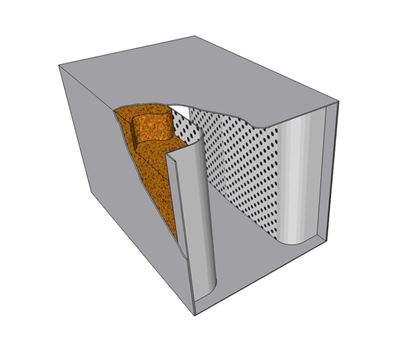
Figure 1. Basic ATD with Acoustic Lining.
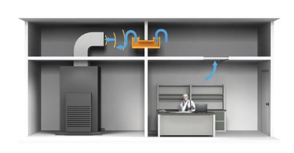
Figure 2. ATD in Use.
Identified Issue
A typical problem found in RA systems, that utilise a plenum rather than a ducted system, is not enough RA finding its way back to the AHU. In this case the number of installed ATDs is insufficient to allow the correct amount of return flow and is creating positive pressure build-up. Effectively, the mixing chamber (entire plantroom) is being starved of its required RA (under negative pressure) and the CO2 monitoring system, not seeing excessive CO2 levels, won’t allow any more OA in. Therefore, the only available air remaining is from outside the plantroom in the corridor (which is under positive pressure) and is now being sucked (willingly) into the plantroom and creating excessive whistling noises. Figure 3 shows a basic sketch I drew to aid in visualising the situation.

Figure 3. Situation Hand Sketch.
What’s possibly exacerbating the issue is the CO2 monitoring system. Because the RA is being restricted the CO2 monitor is most likely reading low CO2 levels, therefore signalling to reduce the OA intake as it’s not required to dilute the RA. This then creates increased negative pressure inside the plantroom and thus makes it easier to pull in air from the corridor due to the AHU fan demand. It then become a vicious circle as this extra air being pulled in from the corridor is most likely to come directly from the SA grilles, with little human traffic, meaning the CO2 levels will low.
Depending on how much the RA is restricted will determine the severity of the symptoms found.
During construction there were a number of design changes, doors being relocated and the like, which caused the air flows to change slightly. This however, is not deemed a significant reason for the symptoms being experienced.
Resolution
The resolution quite simply requires increasing the number of air passages through the full-height walls. As stated this had already been designed for and implemented through the use of 5 No. ATDs, however, clearly more are required. Figure 4 shows the drawing mark-up with existing ATDs (blue) and my proposed design for additional ATDs (pink).
Previous Resolution Attempts
The mech contractor had already attempted to solve the issue by cutting holes in certain locations within the full-height walls. While this may have helped to alleviate the issue, it has not solved it.
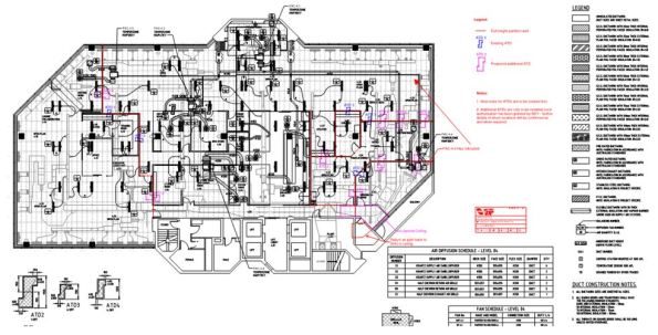
Figure 4. CAD Drawing Mark-up.
Design Calculations
I conducted some basic calculations to determine the number of ATDs required, allowing the same rate of return air flow as that being supplied to the floor space, resulting in a more favourable neutral pressure.
The calculations included splitting the floor space into sections, boundaries based on the full-height partitions, where I then added together the SA from each diffuser in that section. I then worked out the area required (using Q = A x V based on a 5 m/s air velocity) to get that flow rate through the wall to the next section. I continued the same calculations for the other sections, remembering to carry through the flow rate from the previous section as the RA from the entire plenum space is trying to get back to the same point (left to right when viewing the dwg).
In total I calculated an additional 9 No. ATD2’s (600mm x 400mm) were required. In truth it’s only the cut-out dimensions that are actually required to solve the air flow issue, not the ATDs per se.
Design Considerations
There are important factors in positioning ATDs within a plenum: availability of space between the upper floor slab and false ceiling, space between other services, and understanding the use of the rooms either side of the full-height wall to name the most important. All these were considered in my design. The last consideration, the use of rooms, is particularly important as this could determine the possibility of negating the need for ATDs in a particular location altogether. That is not to say there wouldn’t be a cut-out, just no ATD installed, so still allowing the required passage of RA.
COAs
Two COAs were considered, with time, cost and quality in mind. However, before the suggested COA is carried out a number of RFIs must be answered by the mech contractor, these are: confirmation of the location and size of previously made cut-outs, and an estimate on the availability of space to install the ATDs. The location and size of previous cut-outs is important as these could be utilised and potentially increased, based on the calculated sizes above, as suggested in the COAs below.
COA 1
This would be conducted in two stages, both during out of hours so as not to disrupt staff working:
Stage 1 – Make the cut-outs in the full-height partition walls as indicated on the mark-up drawings. This should solve the issue, however may lead to excessive cross-talk. If the room pressures have been restored, the symptoms disappeared and there is no detection of cross-talk, or it is at an acceptable level, then the works will be complete.
Stage 2 – Assess the level of cross-talk, if it is not acceptable then conduct stage 3.
Stage 3 – Install the ATDs in the designated cut-outs, thus solving the cross-talk issue.
Pros and Cons
The main pro is: If stage 1 is sufficient there will be a substantial cost saving on negating the need for possibly all or at least some of the ATDs; each approx $1000 a piece depending on size.
The con is: If stage 2 is required then there would be extra labour costs due to the mech sub-contractors having to go back a second time to install ATDs.
COA 2
Do as COA 1 but all stages in one go.
Pros and Cons
The main pros are: Reduced labour costs for the mech sub-contractor and all the work being done in one go means minimal disruption.
The con is: The ATDs may be superfluous in solving the issue and therefore present an unnecessary cost.
Noise Level Consultation
I discussed the issue with our acoustic engineer and am confident that the overall cheapest option, that still achieves the required acoustic quality levels, is COA 1. This is based on not all the positions identified requiring ATDs. The exact number cannot be confirmed until a further assessment is conducted post stage 1 of COA 1.
Recommended Solution
The recommend solution is COA 1 but I envisage having to discuss these actions with the mech contractor, as alluded to, to get answers to my RFIs. This may also involve going on site to discuss further.
Update
During the preparation of this blog I learnt, through a third party, that the mech contractor indicated it wouldn’t be possible to fit the ATDs as proposed due to lack of space in the partition wall around the plantroom. There were some other suggestions mentioned, such as, installing a large transfer grille in the corridor/plantroom wall but this would need to be quite large to solve the issue and would likely look pretty rubbish not to mention noisy. It would then require an attenuator on the plantroom side to attenuate the plant noise. I think the next step is to meet with the mech contractor to discuss options.
What did I learn?
A key observation, which extends to all projects, has been that no matter who you ask for advice, you will always get a slightly different answer. The key principles will be the same but individual engineers’ will be basing their ideas on their accrued experience. I suppose this highlights the meaning of engineering, derived from the Latin ingenium, meaning ‘cleverness’ and ingeniare, meaning ‘to contrive or devise’, and just goes to show there is more than one way to skin a cat. The challenging part is to learn how and why these little design nuances can aid in delivering a more technically, sustainable and economical solution and therefore aid in refining your design skills. The technical solution also needs to be balanced with any political considerations, especially when wishing to win any future work with the same client.
I also learnt about the disadvantages of plenum based return air systems and found this article helpful in understanding:
In Other News
I organised a surprise birthday present for the wife; a great view of Perth from 1500ft. It included a shot of JHG’s PCH project and the new sports stadium, managing contractor being Brookfield Multiplex (new alternate Ph2 attachment). I’ve also included a few other snaps…
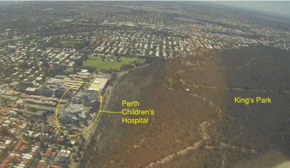
Perth Children’s Hospital.
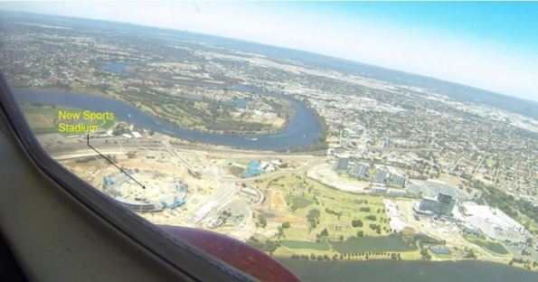
Perth’s New Sports Stadium – Still in the structural build stage.
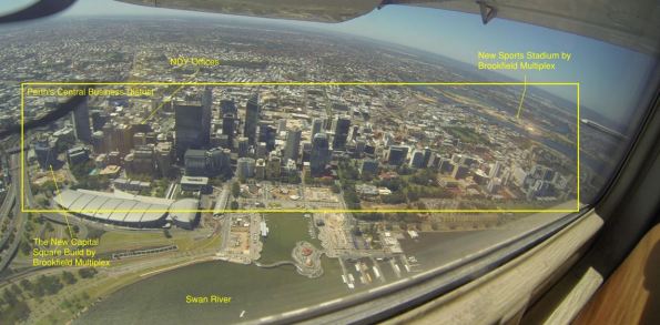
Perth’s Central Business District.
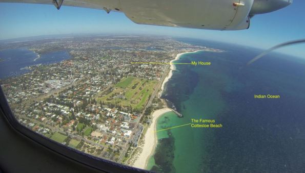
WA Coast Line.
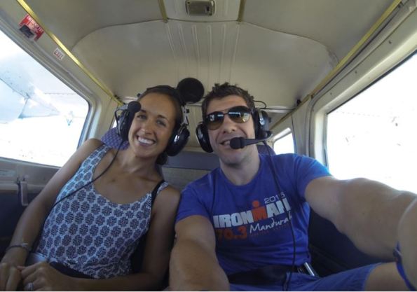
Happy Wife Happy Life!
Oz NDY – Shirking Work or Exercising Moral Courage?
Introduction
This wasn’t my intended blog but I wanted to share this now as it only happened yesterday. This blog covers my reactions to being tasked with a piece of sustainability work that I feel is not aligned with my DAP and therefore is likely to fall short of meeting my UK-SPEC requirements. I’m not one to shy away from work but I feel there is sound justification for doing so in this instance.
Background
When I first arrived here I made it a point to explain my raison d’être to both my immediate boss and mentor. I talked through my DAP and expressed examples where I thought I could meet my outstanding UK-SPEC requirements. In particular, E3 – undertake activates in a way that contributes to sustainable development. My take on this, pretty much identical to the bullet points from the UK-SPEC, was to get involved on a new project where I could conduct the stakeholder engagement piece, understand which star rating (on the Green Star spectrum) they wanted to aim for, and be creative and imaginative in coming up with design solutions. Well it hasn’t quite panned out that way…yet.
Issue
The week prior to my immediate boss arriving back in office from extended holidays (cue identified miscommunication) I was given the heads up that there was some sustainability work I could help out with. This seemed to be well timed as one of the sustainability team was about to depart on maternity leave.
On conducting the initial sustainability meeting/training to understand the project and my involvement it became very apparent that what was actually being asked of me was nothing more than an admin and certificate gathering task.
The project
The project, Capital Square, is a new development on the edge of the Perth CBD and the developer has a major tenant, Woodside (in the mining, oil and gas industry) ready to move-in once complete. They were promised all kinds of sustainable initiatives in their current tenancy but the building owner hasn’t come through on any of them. So, they are eager to move into Capital Square and have expressed their need for all the bells and whistles. In Green Star rating terms this translates to a 6 Star building which requires 75 of 100 pts to be awarded the World Leadership title (there isn’t any higher rating at present).
Issue continued…
This all sounded great until I was told that all the Environmentally Sustainable Design had been done and the big push now was to compile all the relevant information (certificates and documents) that provides the evidence of the building actually meeting the points they aspired to. NDY use their own purpose built template (in excel) in which to track the status of this information. The end state being to submit the collated information pack to the Green Building Council of Australia (GBCA) by the end of Mar 16. A quick estimate means that I would be spending 50% of my remaining time on Phase 3 doing this admin based work; not a very constructive use of my time. I’m not saying that I wouldn’t learn anything from doing this work but I can easily get the majority of what I need from a simple review of the template used for this project, which I now intend to do. However, I don’t see any merit in actually going through what seems like two months of torturous spreadsheet compiling.
What did I do?
Immediately, in the meeting, I asked more probing questions to confirm my view of what I thought was being asked to ensure there wasn’t more to it; there wasn’t. I then explained my particular circumstance which immediately confirmed to me that my requirements were not communicated when my stand-in boss set-up the sustainability work I had asked for. It’s not a massive issue but my view is that it all too easily fell into place and solved a resourcing issue but which neglected to consider my needs. I’m not suggesting for a minute that I’m above doing this type of work, or doing as I’m asked in general, but when you consider that we are actually employed under unique circumstances then something needed to be said.
On reporting this to my actual boss, who happened to arrive back on the day this meeting took place, his view was pretty clear-cut. He said “I thought that was just admin work, like what they give to graduates, you’re not going to get anything out of that”.
His view echoes my main justification. I am better off spending those two months project leading on another tenancy fitout project and putting into practice all that I have learnt from my current project lead role and gaining more experience in competencies A1 and A2; also on my DAP.
What did I learn?
You are the master of your own destiny throughout your attachment. Well I actually knew that already but it has been a good example of reinforcing it. No one is going to drive you to follow your DAP so when situations like this arise you have to stand your ground and speak up; with carefully considered and justified reasons that is.
In other News
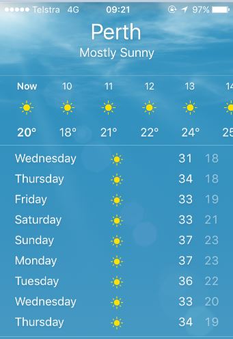
With all this talk of snow I thought I’d share Perth’s weather forecast…so what? Yes my A/C at home has been working over time.
Oz NDY – Vetwest Animal Hospital.
Introduction
Introduced previously is my current short-term project; designing a fitout for a Vetwest animal hospital. This is my first project as a Project Leader (PL), essentially project managing from start to finish. Before leave I/we submitted a concept design solution for review by our client, the managing contractor, Perth Citi Fitout (PCF) and their client, the building occupier, Vetwest. This blog discusses the on-going project and challenges.
Concept Solution Review
Reading my first client email correspondence, with reference to the concept design, I am already sensing the commercial challenges of the client facing side of design consultancy. PCF are concerned about changes we have made from their initial thoughts, particularly referring to the mechanical design of the air-conditioning (A/C) system. This is because we have included additional equipment which will increase their costs and eat into their profit margin. Without seeing the contract between Vetwest and PCF it’s hard to know if PCF are on a fixed price contract or not. I think they are as indicated by the technical data sheets they supplied us for the air conditioning units, which included a supplier quote of AUD $55k for 3 x Daikin split DX Variable Refrigerant Volume/Variable Refrigerant Flow (VRV/VRF) units.
Our concept design suggested 4 x packaged units costing circa AUD $70 – 100k. This was based on the layout split into four zones and included a dedicated unit for the HEPA filter in the surgery room. Packaged units aid in mitigating operational interruptions for maintenance as they will all be roof mounted. But PCF’s proposed split DX units would mean the indoor unit being located in the ceiling void which would disrupt operational use, including treatment/surgical operations. There are also other benefits of using packaged units but PCF, with confirmation from Vetwest, want to keep the costs down. That’s absolutely their prerogative but our view is split DX units are more suited to domestic buildings rather than commercial.
Although not our contractual duty, we feel we must look out for the interests of Vetwest and provide a design solution to their requirements, especially as they are seeking Australian Veterinary Association (AVA) hospital accreditation. This will indirectly aid PCF because if they fail to deliver the scope of works in accordance with Vetwest’s specification then they will become liable for variation charges.
How to manage this…
In order to tackle this I set about highlighting the benefits, via justification, of our design. Annoyingly, this information had already been submitted, written into a Consultants Advice Note (CAN). But, not wanting to simply reiterate this information, I set about giving the problem its due diligence by providing additional information which I gained from further research. This gave me the opportunity to review our design myself and pick-up on a couple of improvements that could be made. For example, the specific requirements of the Accreditation Scheme for the AVA (ASAVA) referring to the prohibition of any Air Transfer Grilles (ATG) and requiring a dedicated exhaust fan to outside the facility for the isolation room. This also included a dedicated exhaust fan and a motorised volume control damper connected up-stream of the supply air (SA) grille. This ensures the design’s ability to maintain negative pressure and if the exhaust fan should fail the SA damper can be completely closed to avoid positive pressure build-up.
Talking this through with the Project Director (PD) we came up with a compromise and amended the concept design, see figure 1. We reduced the number of A/C units to three, utilising the split DX units PCF proposed to keep costs down, by combining the surgery room with the rooms in the purple zone. The surgery room would therefore require its own SA leg of ductwork and a dedicated inline booster fan to overcome pressure losses from the HEPA filter unit. It would also still require a dedicated exhaust fan as air from the surgery room cannot be returned to the main A/C unit.
Other changes were: combining exhausting air from the cat and kennel rooms, via linked ducting, which reduced the number of exhaust fans by one; reducing rigid ducting and replacing with flexible ducting where possible, but still in accordance with BCA guidelines where maximum lengths of flexi duct must not exceed 6m; and; designing in two options for drainage, one using bucket and floor waste traps, the other a grease trap. This was TBC by Vetwest as to the outcome of their application to Water Corp for a trade waste permit. Ideally this should have been done before so we knew the exact requirements for which we are being asked to design to rather than us having to suggest multiple solutions.
I also drew-up three hydraulic concept designs for: hot and cold water, oxygen and suction, and drainage.
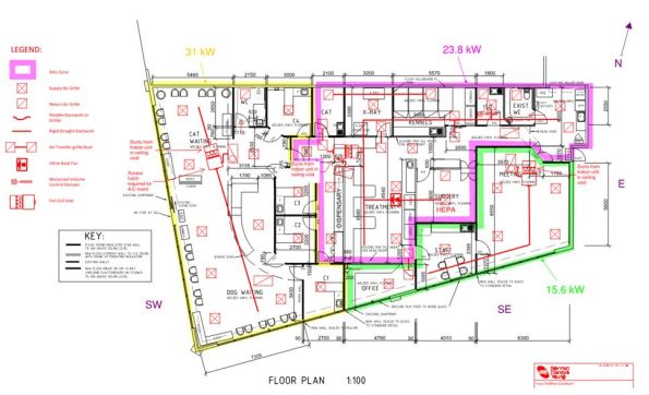
Figure 1. Revised Mech Concept Design.
Next steps
These changes were submitted to PCF and Vetwest for review and I am awaiting their feedback. Vetwest physically gain access to the building on the 1 Feb so is the earliest any on-site works can commence. Therefore, once the concept design has been approved and frozen (hopefully in the next two days) we have said we can complete final detailed design two weeks from then. So hopefully ready by the 1 Feb. In the mean time I am cracking on with software based heat load calculations so I can size the A/C units for the supplier to order in and stay inside lead times.
Heat load calculations
Figure 2 shows an example of my initial estimated heat load calculations – using the Australian Institute of Refrigeration, Air Conditioning and Heating (AIRAH) template.
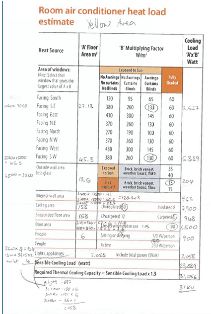
Figure 2. Estimated Heat Load Calculations for the yellow Zone.
For detailed design NDY currently use a software package called TRACE to calculate heating and cooling loads in order to aid sizing of key plant, such as, A/C units, boilers, etc. It is shortly to be superseded by an advanced programme called CAMEL; I vaguely remember Ben Foster making a pun about it when comparing it to Hevacomp. CAMEL has the added bonus of integrating its building details and input data with another software package called BEAVER. BEAVER is a building energy simulation programme which is used by the majority of building owners/occupiers to estimate: heating, cooling, fan, equipment and lighting energy consumption. However, for this project I will be using TRACE.
What did I learn?
In summary, so far – a lot! It really is just like conducting one of the projects from Phase 1, so in that respect that was perfect training. The only real difference is the standards being Australian – but then they are very similar and searching for them is the same.
Stakeholder engagement is key. We had an initial project meeting before Christmas and followed it up with a site recce. Getting stuck into the detail this past week has highlighted a number of areas that needed clarification. Therefore a number of RFIs, directed at both Vetwest and PCF, were sent, all to aid project management. The good old fashioned telephone being the preferred method, with all communications followed up in writing, be it by email or CAN.
Oz NDY – From One Hospital to Another.
Introduction
I’ve now been in the design office for 2 whole weeks, working in the Interiors/Tenancy Section in the Existing Buildings Department. In summary, we design all mech, elec and hydraulic services for existing building refurbishments, usually office/business fitouts. Overall office work leading up to Christmas has been a little frantic, mainly involving clearing deadlines and getting tenders out for new business for the start of the New Year. I have undertaken a few interim tasks as stated below with my first real project role coming in the form of an animal hospital fitout – kind of apt coming from the PCH project.
Interim Tasks
The following three tasks were given to me as more of a filler and introduction to the types of projects I’ll be getting involved in.
- Fee Proposal Review. A review of NDY’s fee proposal for the replacement of a generator exhaust. The mechanical contractor originally approached by the client were only a small company and felt the proposal was too detailed and consisted of too much management terminology for the simple requirement. There was nothing wrong with the proposal and we deemed it fit for purpose so advised the client to explain this to the contractor. If they still didn’t agree then we advised them to re-tender to a more suitable one; who could see past the management procedures and policies, that I feel they were deeming too complex.
- Giving Technical Advice via a Consultant’s Advice Note (CAN). The CAN was for the reprogramming of the BMS in a recent office fitout we had completed where two separate floors were adjoined by a central stair. The CAN gave a technical explanation for the need to consider both floors as one in terms of smoke management in a fire event when creating the fire and smoke cause and effect matrix.
- Restricted Return Air Path. This consisted of a study of the AHU return air path in a new office fitout where, due to the type of return air system used, being via extract grilles straight in to the ceiling void acting as a large plenum, it was found that obstruction from sections of full-height partition walls were restricting return airflow. We came up with a solution to install a number of transfer grilles through particular sections of the full-height walls. The trade off being potentially increased noise levels for better recirculation.
Short-term Projects
I have just started my first main project, my role being the Project Leader (PL) for the fitout of a new animal hospital. The current space if no more than an empty warehouse serviced by 3 No. Evaporative air-conditioning system linked through flexible ducting (which they seem to love over here). There is also an existing toilet and lighting throughout.
The PL roles sees me being the client facing project manager reporting to a Project Director (PD) who is also doubling-up as the mech technical lead. My boss (also mech biased) has been helping out and accompanied me to my first client meeting and site inspection; he will be on extended leave post Christmas till the end of Jan so has basically helped me get the project rolling.
In terms of detail at this stage our client, Perth Citi Fitout, are the Managing Contractor who have already put together construction force of various subcontractors based on the scope of works from their client, Vetwest. They have Nagel, architects, who have designed the fitout so we have a pretty good idea of what they want. The services are pretty straightforward with the bulk of design work being the mech air-conditioning system.
At present the MC has budgeted for a complete strip-out and new installed system so that’s exactly what we are going to design. We did see if the existing evap units might be useable but decided pretty quickly to replace them. This was mainly based on the poor effectiveness of evaporative cooling in high humidity conditions. Granted that the Perth climate conditions produce mostly dry heat but there are occasional humid spells in the winter months, which realistically would only offer a small delta T due to evaporation becoming more difficult proportional to the water content present in the air.
The MC issued us a concept mech layout but from our meeting and discussions over the number of HEPA filtration units required we went away and conducted our own research. The two main points were, the requirement for a grease trap for the wastewater drainage system and HEPA filtered units to be installed in all locations where animals would be.
Both of these are being investigated and I am awaiting specialist confirmation. My initial thoughts being thus:
Grease Trap. After stakeholder engagement it was identified that the areas where animals (primarily dogs) will be kept for long periods of time, the kennels and cages are fitted with special chemicals that soak up urine and water content in faeces. These are regularly cleaned out and disposed of in specific excrement waste bags so it is my view that normal wastewater drainage will be suitable. Of course the Water Corps may have a different view and I also need to check the Building Code of Australia (BCA) Guidelines.
Multiple HEPA Filters. Again after stakeholder engagement it was found that Vetwest are wishing to apply to the Australian Veterinary Association (AVA) to seek accreditation of their hospital accreditation scheme. The Vetwest proj mgr stated that under the AVA’s standard they required all air-conditioned spaces where animals are present to be HEPA filtered. It was evident in the mtg that they didn’t actually know how this worked as they were talking about mixing normal supply air and HEPA filtered air in the same space – which obviously negates the very clean air provided by the HEPA filters. What we did know was that just like in a human hospital the surgery room needs to be supplied by HEPA filtered air but I don’t think other areas do. To confirm I researched the AVA standards and found nothing relating to HEPA filtration at all so posed the question to one of their standards testers – I’m awaiting a reply.
NDY’s Concept Design
With these answers outstanding I cracked on and came up with a concept mech (air-conditioning) layout. I split the space into four zones and plan on using 4 No. Packaged DX Units (yet to be specified). These DX units will be mounted on the roof (where there’s plenty of space) and consist of ridged ducting for the main run with flexible ducting to each supply air grille. Figure 1 shows the draft concept design. This along with a Consultant’s Advice Note (CAN) explaining our justifications for the system type will be finished off and sent to the MC for comment before Christmas.
Post Leave Continuation
On my return from leave and after consultation with the MC over our concept design I will then begin the detailed design. This will initially consist of using a software package called Trace which gives you heat load calculation so I can then size my packaged units. I’ve had a quick play with it already and it’s very similar to Hevacomp but with more experience I’ll try and draw out some more detailed comparisons. Then I’ll have to size all the ductwork to achieve the correct flow rates etc that will lead to cost planning. At the moment the MC has quoted AUD $55k for 3 No. units and our 4 No. Packaged DX Units is looking around the AUD $70k mark. I will then move on to the hydraulic system, mainly consisting of a reticulated Oxygen supply and Suction system.
Project Reflection
Being part of the Interiors/Tenancy Section means that I will hopefully have a number of short-term design projects to PL on. This will provide me with a good basis for reflection and help steer subsequent projects in order to build on my professional development and focus on any outstanding UK-SPEC requirements.
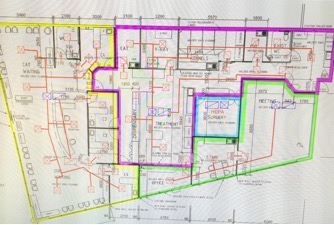
Figure 1. NDY Concept Mech Layout
This just leaves me to say I won’t be blogging for about 4 weeks as I’m now on Christmas leave…have a Merry Christmas and a Happy New Year!
