Archive
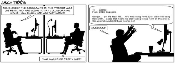
Oz NDY – REVIT vs AutoCAD Discuss…

Introduction
This blog aims to get a discussion going on the topic of utilising CAD packages in your design offices. I’ll kick-off with NDY’s set-up…
REVIT is seen, pretty much construction industry wide and certainly at NDY, as the flagship CAD package. We have a dedicated CAD team that solely use REVIT, although skills do exist for other CAD packages such as AutoCAD.
NDY promote their use of REVIT and like to express this to their client base so they are seen as operating with the latest industry technology. However, there is a problem. I’ll use my current section, Interiors, as an example of a typical project.
Problem
The Interiors Section of the Existing Buildings Department focuses on short-term projects, usually 6 – 8 wks. Therefore, turn-around times for CAD drawings, in particular, are tight. If the design is of specific technical complexity then usually REVIT will be: a) requested by the client and b) preferred by us as we can programme in the CAD requirements and resource through our dedicated CAD team. However, due to short project deliverable timelines and sometimes more basic CAD requirements along with client requests for only needing simple drawings, it can be a lot quicker if these are created ‘in-section’ (opposed to in-house) using AutoCAD. This negates the need to resource to the CAD team which they prefer as their bread and butter work, for the core departments working on large complex projects, can continue unhindered.
The AutoCAD capability exists in the Interiors Section so this affords us great flexibility in managing project deliverables and in-turn removes pressure from the wider office.
In addition, NDY also have an outsourcing capability in Indochina where we have a process in place that outsources CAD requirements. A great capability but for short-term work the lead-time required for the process to work efficiently means that we still prefer to do this in-section. It also means we can make amendments and re-issue drawings in the most efficient and effective manner.
As time is money you can see how this creates cost savings, especially when you compare the technical skills required between using basic AutoCAD and REVIT.
Discuss…
I’ll leave it there with the hope to spark a discussion about your experiences and thoughts…
Edited with Outsourcing CAD process.
Oz NDY – Transitions In More Ways Than One
Introduction
In this blog I will cover the lead up to transitioning between Phase 2 & 3. It aims to help out the Phase 1 students and hopefully give you a few pointers come your impending move – it rushes up faster than you think!
Background
You will be fully aware that Phase 2 in Australia is set-up with John Holland Group (JHG), so apart from sorting out your own admin for the move, work wise things should be plain sailing. However, you should also be aware that Phase 3 – Design Consultancy attachment is partly up to you to organise.
My Experience
The most important thing to factor in is time. Eight months flies by and you really need to give the move some thought early on, allowing sufficient lead-time to jump through a few hoops. My experience could be classed as atypical as I tried to break from what my predecessor did but for, at the time, what I thought were good reasons.
The norm is for the student to move to the office of whoever the design consultancy was for your JHG project. This has pros and cons:
Pros
- You will have had some interaction with them at some point on your project and hopefully built-up a good rapport.
- You may be able to visit their office through working on an area of the project; a great way of meeting more employees but more importantly get a feel for the vibe of the office. I did this and it really helped with my decision.
- If the previous PET student went there then they will have a very good understanding of what the programme is all about and importantly how to manage you. I think this is invaluable and sealed the deal for me in the end. Although it’s not difficult to inform a new office of all that info, they may have a different agenda for you and by the time you work that out it might be too late.
- Equally, if the student you follow is a good egg then the office will understand your experience, capabilities (especially managerial) and general ‘can-do’ attitude. This can also be tempered with them knowing your other commitments; academic studies etc.
- It also reduces the number of hoops and admin for JHG and the design office to do.
- I was told that for conflict of interest reasons that I would categorically not be working back on the JHG project. This is a positive thing as it gives you a clean break and doesn’t get you working on the same project tasks; potentially reducing your chances of gaining more breadth in usually much needed competency areas. It doesn’t however stop you from imparting your newly gained knowledge and experience to help out your design office colleagues; only being in the office for three days I managed to do this with one of my very first tasks as I have the understanding from being familiar with NDY documentation.
- Another related positive is your ability to see things from the other side of the fence and maybe understand why certain decisions were made without the JHG inflated spin.
Cons
- You may have had to deal with the design consultancy staff whilst wearing your Managing Contractor (MC) hat where you may have had to show bias to the MC in order to please your chain of command, only to then find yourself working alongside the design office staff or be a member in their team.
- There may be other design consultancies that have better projects on the go.
- A diminished office and demotivated atmosphere. They used to occupy the entire 11th floor but have reduced in size due to reduction in work and so are looking to lease out the other half of the office. [I have to say that although they have condensed into a single side of the office the atmosphere and spirit seems good].
Decision
It may seem, from the pro – con balance, that it’s a no-brainer in following-on in your predecessor’s footsteps. But, there may be very good reasons for a change. For me NDY were having a rough ride at the hands of JHG’s management on the PCH project and there were a number of design challenges, which no amount of senior management meetings on the 18th green were going to resolve; there could still be a court hearing come the end of the project. To that end and with repeated warnings (slurs) from JHG staff it seemed like a good idea to at least investigate alternative attachment opportunities.
I engaged with two other big consultancies in Perth, Wood & Grieve Engineers (WGE) and WSP Parsons Brinckerhoff. WGE had won the bid for the new Perth Stadium, which I thought looked like a great project but unfortunately they had been laying staff off and presentationally they said it wouldn’t look good taking on new blood. WSP was more of the services director at JHG trying to line me up with their office, but i just couldn’t shake the feeling that somehow it was mates doing each other a favour and so didn’t feel my best interests were at heart.
For both I did a fair amount of research, rewrote my CV, covering letters etc and even used known acquaintances on the inside to at least get an interview (hence the comment above about needing lead-time). After weeks of not really getting anywhere it was on the advice of another design consultancy, Cundall, whom I was working with on the PCH project who gave me the low-down on each prospective office and ultimately helped me make my decision to stick with the original plan and join NDY.
I suppose the important point here is to not just follow the norm because that’s what others before you did. Investigate for yourself and use as many sources at your disposal as possible to aid you in your decision. But remember this… it is you that’s going to be working at the office for the next 6 months and it’s your needs and requirements that must be met, which therefore should be your priority over everything else; remember the end-state is to become a Chartered Engineer.
I don’t know if any other Phase 3 students would like to echo my experience or add their own?
In Other News
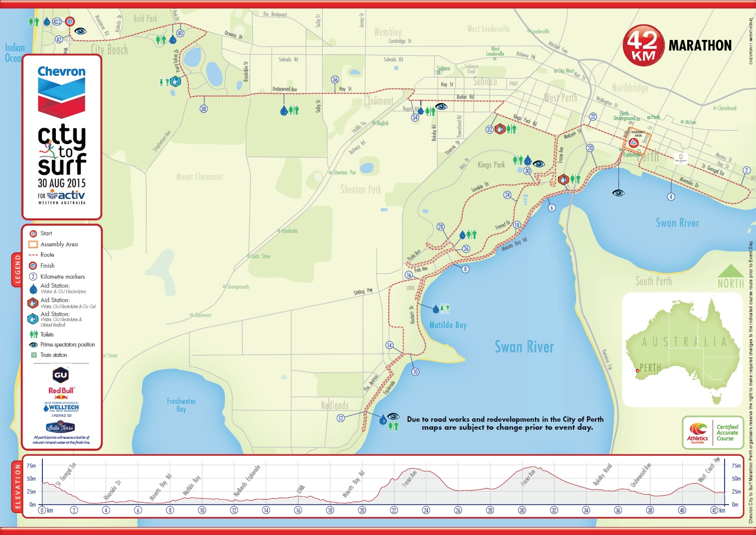
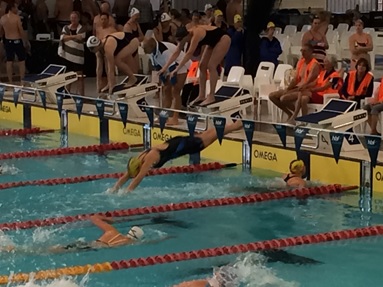
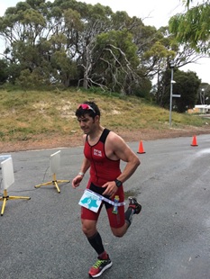
I completed Ironman Western Australia at the weekend. A tough 6 month training programme, juggling work and study, resulting in a lot of blood (when I broke my thumb) and sweat, but thankfully no tears. I managed to get a PB in a total time of 12hrs 7mins (beating my previous best by 1hr 13mins) for the 3.8km swim, 180km bike and 42.2 km run.

Enter a caption
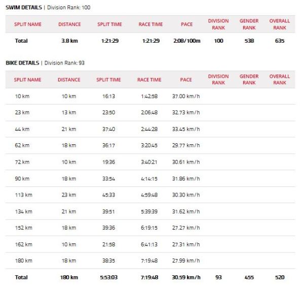
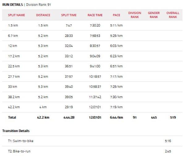
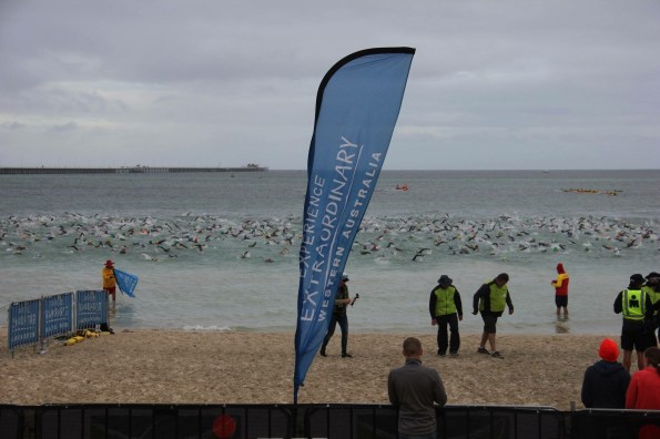
The weather caused mixed emotions with high morning wind and rain creating 1 – 2 metre swell, causing somewhere near 100 participants to jack-it-in through vomiting and general panic during the sea swim to sections on the bike course cycling into a 50km/h head wind. Thankfully though the cloud cover and low 21°C temperature meant a cool bike and run. With 1205 competitors starting, coming home in a divisional ranking of 91st (based on age category) and 519th overall, I was broadly happy. As a comparison the winner, a pro-athlete completed the course in 7hrs 55mins, an Australian course record – phenomenal!
At least now I can have my life back, lie-in at the weekends, not feel guilty about missing a training session and drink alcohol…until next time; which won’t be anytime soon, well not for the long course anyway!
Enter a caption
Sea swim around the iconic Busselton Jetty – you can just make out the turn point in the distance.
Enter a caption
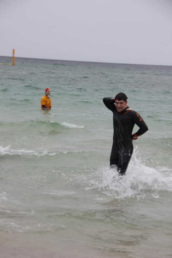
Glad to be out of the washing machine.

Enter a caption
90km down – another 90km to go!
Enter a caption
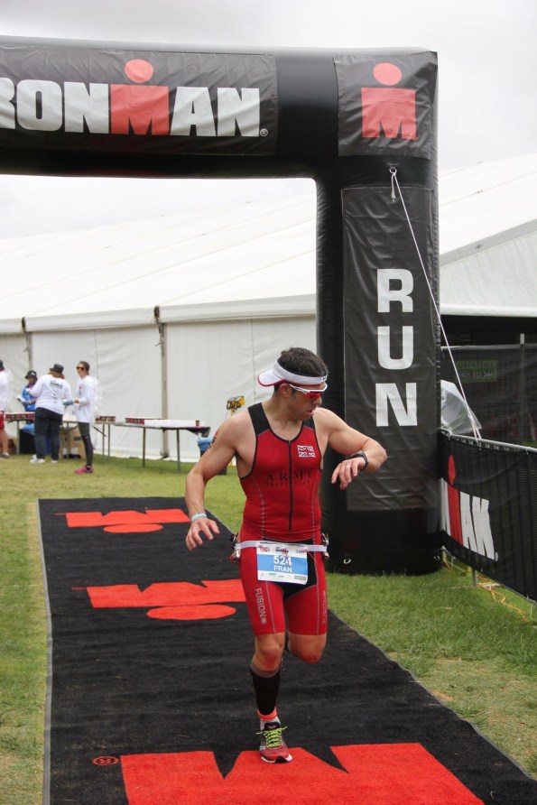
Only a marathon to finish off.

Enter a caption
Done!
Oz PCH – Commercial and Contractual Tasks.
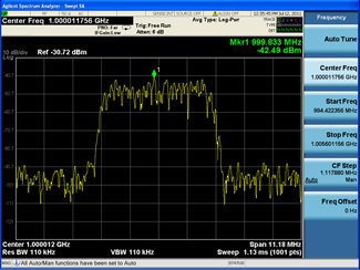
Example Spectrum Analyser Recording
Introduction
In this blog I will cover various commercial and contractual tasks I have undertaken whilst working alongside the Commercial Team. These tasks came about as a result of my continual DAP review to ensure that I have met as many of the UK-SPEC requirements, at the right level, as possible.
The reason I am conducting these types of task now, compared to the majority of my peers who have done so early-on in their attachments, comes down to timing and project availability. I always knew entering the project at the stage I did meant that the ship had already sailed with regard to the majority of specific contractual stuff. Therefore, through my DAP and in consultation with my line-management I sought out and conducted the following:
RF/EMF Testing Tender Process (B1, B2, C1 and C2)
Here I was responsible for the procurement and tender process for the RF/EMF Testing works package. This was to confirm that previously omitted shielding, via a value engineering exercise, was indeed not required for Electro-encephalo-gram (EEG) recording rooms. An early study conducted by JHG concluded that, based on their needs (not having to architecturally redesign rooms) and the views of various vendors (specialist medical equipment suppliers), the latest technological improvements in medical equipment reduced RF/EMF emissions enough to negate the requirement for shielding. A survey was also conducted of a number of hospital projects nation-wide to confirm what they had implemented in terms of mitigation for RF/EMF emissions.
Why Required?
The client had requested the testing as a ‘belt and braces’ insurance policy, which was absolutely their prerogative especially when you consider the potential implications of the effects that RF/EMF emissions interference can have on critical medical examination equipment. In particular it was the concerns of the client that the EEG recording equipment, conducted by a Neurologist, as the ‘victim’ would see interference from the Evoked Potential/Transcranial Magnetic Simulation (EP/TMS) equipment, the ‘source’, and other potential RF/EMF emitting ‘sources’ such as: the large power motors in the vertical transport lifts, and the standard electrical load running round the department.
The Process
The tender process involved me understanding the procurement options in terms of which type of contract agreement best suited the works to be carried out and the potential budget. Writing the scope of works meant understanding the risks associated with the possible outcome of the testing and therefore ensuring that potential issues were mitigated where practicable. A key risk identified meant that stakeholder engagement was vital to ensure co-ordination of important test conditions where concurrent activates were to take place, including: live EEG testing, minimum 50% electrical power load in the building, specific medical equipment (EP/TMS) being in location and operational and the nearest vertical transport lift in operation. It also included identification of resources required and costs to the project.
There was a fair amount of admin required to prepare the tender packs for seven tenderers (a minimum of three is compulsory as stated in JHG policy) which resulted in only four returning tender submissions. Negotiations over specific scope of works details and costs were had and agreed, forming part of the tender selection process; I liken preparing the RFIs for the tenderers to being handed a planning pack for a Search task on the RESA course, having to ask the right questions in order to draw out answers and make deductions.
The final part of the selection involved a telephone interview with: myself, a Contracts Administrator (CA), the services manager (my boss), and obviously the tenderer. Normally this would have been face-to-face but this particular preferred tenderer was based on the East Coast. Once certain questions relevant to technical and commercial concerns were cleared-up we deliberated over the options before coming to a decision and me writing up the recommendations document which was sent internally for manager and director sign-off. I also completed the Consultants Services Agreement (CSA) form of contract before sending out and sealing the deal via formal notification; this also included non-successful letters being sent.
Implications of Test Failure
If the testing fails, and by fail I mean there is significant interference caused by an electrical source somewhere in the vicinity of the EEG rooms, then a further study will have to take place in trying to mitigate the source. Worst case, the affected rooms may require the shielding that was originally omitted which would not only cost heavily due to having to strip-out a completed room but would also incur a delay. Dependant on how many rooms required shielding, this could possibly affect practical competition but my guess would be partial occupancy at worst but could still attract liquidated damages; currently at $180,000 per day for the entire facility so would most likely be less.
This has all been finalised on my last day working on the project and it’s a shame I won’t get to see how the works package pans out; it being handed over to the services manager to implement in Jan 16.
IC Energy Pty Ltd Works Package Review (B1, B2, B3, C1 and C4)
This consisted of a review of 226 Variation Orders (VO) and associated costs to the Temporary Construction Power & Lighting works package, comparing the original contracted tender costs to that of the current/forecast practical completion costs. I won’t discuss too much of what was found from the review here as I am writing this up as a managerial themed TMR. Suffice to say the original budget increased by 60% (AUD$ 1,374,298) currently at AUD$3,655,109.02 but with the potential to climb to circa AUD$4 million by practical completion. A myriad of managerial and decision making errors attributed to this overspend which the review has brought to light with the intention to be used as an example of lessons learnt for future projects.
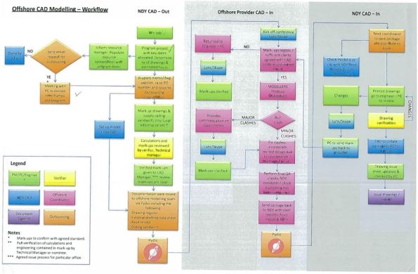
Variation Order Claims (C1 and C2)
I reviewed a Variation Order (VO) claim, using the process in figure 1, from Fire Safe Systems who were contracted to provide wet and dry fire suppression site-wide. Under the original contract a number of diagnostic and theatre rooms housing very expensive medical equipment such as: MRI machines, specialised surgical operative tables and the like, were all to be fitted out with pro-inert gas (IG55), using 50% Nitrogen and 50% Argon. The intent being that if in the event of fire it could be suppressed and extinguished using a gas system instead of using a traditional sprinkler system. Thus ensuring any medical equipment not damaged by the fire would also be free from other damage due to using the gas suppression system.
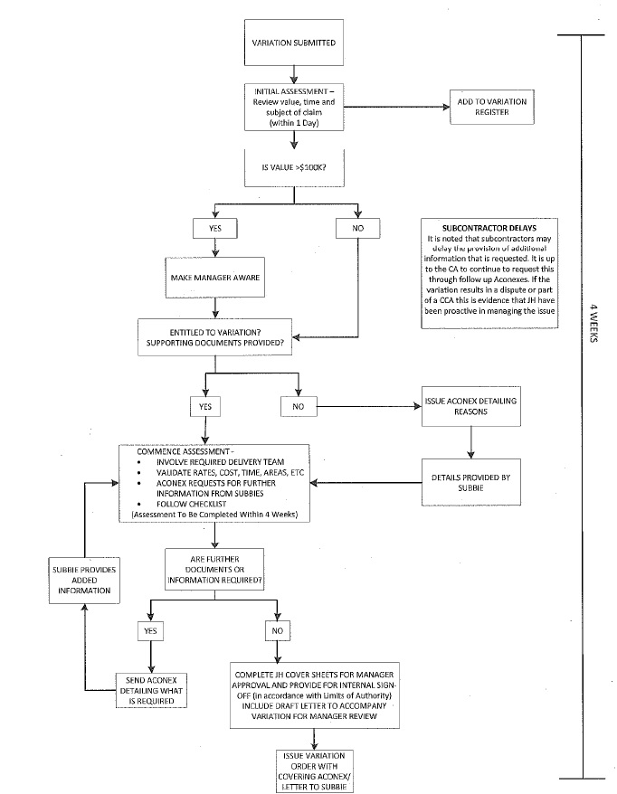
Figure 1. Variation Order Claim Process.
However, the VO came about as a result of the pro-inert gas system design being changed to a pre-action ‘double knock’ sprinkler system. This was due to the design not accounting for the space required to store the quantity and size of gas cylinders along with regular storage and maintenance concerns.
Pre-action systems are hybrids of wet, dry, and deluge systems, depending on the exact system requirement. In this case a double interlock, also known as ‘double knock’ system is used.
The operation of double interlock systems are similar to deluge systems except that automatic sprinklers are used. These systems require that both a ‘preceding’ fire detection event, typically the activation of a heat or smoke detector, and an automatic sprinkler operation take place prior to the ‘action’ of water introduction into the system’s piping. Activation of either the fire detectors or sprinklers alone, without the concurrent operation of the other, will not allow water to enter the piping. With the presence of fire confirmed, water is forced through the piping via a compressor unit but no water enters until a sprinkler operates. Double interlock systems are therefore considered as dry systems in terms of water delivery times. Although not as equipment friendly as the pro-inert gas system, the premise is that the double interlock feature will prohibited false alarm activation and if a fire is present then water damage will most likely be less severe than that caused by fire.
Contractually Fire Safe had to return to JHG the cost associated to the original pro-inert gas system including any testing costs; totalling AUD$ 94,951. This was submitted in the same VO and required a number of RFIs to clarify as the actual figure was never broken out of the original contract sum.
I then reviewed all the costs associated with the new pre-action system, which again required a number of RFIs through emails, phone calls and requesting clarification through marked-up drawings to understand the detail; this amassed to circa AUD$176,000. There were some errors made by Fire Safe in annotating the drawings where they accidently changed the colour coding and nomenclature, which just delayed the review process and JHG trying to do our due diligence.
The lesson here is that all claims need to be justified and substantiated in order to satisfy the Contracts Administrator (CA), or in this case me, to approve payment.
Once the analysis was complete the CA inputted the payment amount into the Project Cost Reporting (PCR) database. I then completed a summary page with the aid of a checklist before submitting to internal JHG managers and directors for their sign-off.
This was then sent to Fire Safe for their agreement and signature of acceptance. This then allowed the CA to update the payment entry within PCR to ‘A’ for approved; it then gets added to the overall project costs.
If the amount is not agreed by the subcontractor then they can take it to dispute but this is seldom done due to the previous communications and negotiations in the initial review process.
One significant difference is when a VO claim submitted by a subcontractor is deemed by JHG to be recoverable from the client. In this case a manager or most likely the project director will hold the payment approval until the client have confirmed they are liable for the cost; a ‘pay when paid’ clause. This is done to prevent the risk of JHG being ‘out of pocket’ for a period of time and used as a delay mechanism, but will still result in the subcontractor being paid eventually; not to be mistaken and different to that of a ‘pay if paid’ clause.
Valuation Payment Claims (C1 and C2)
In order to confirm and approve a typical payment claim, I reviewed one from Fredon (mechanical subcontractor for plantrooms). This consisted of walking round one of the plantrooms with the CA for a visual check to judge the % complete and also as a QA/QC check. We used their payment schedule as the check list and made notes along the way. We then applied a weighting compared to their previous payment and what was outstanding and paid according to that. If there were any major defects identified then this wouldn’t get paid at all until rectified and would roll over to the next month’s payment claim. Similar to the VO process this was then entered into PCR and added to the project.
In Other News
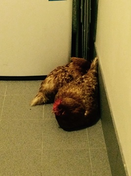
On my return home last night my wife comes out to meet me (something she has never done) and standing clear of the doorway whilst starring round the corner she says “don’t worry but we have an issue”…instantly I’m thinking huge poisonous spider…snake…but no, what do I find cuddled in the corner of the laundry room – two bantam chickens!
Parting Shot
It just leaves me to say this is my final blog whilst working on the Perth Children’s Hospital project – and what a great opportunity and experience it has been. Bring on the move to Phase 3 at NDY!
Oz PCH – EMC Gland Wars: The Subcontractor Strikes Back
Introduction
This is a follow-up blog from the previous Electromagnetic Compatibility Concerns. It discusses the on-going issue of RF emissions leakage from VSDs and their associated mains power cable. Please feel free to re-read my previous blog for the background to this issue.
Outgoing Mains from VSD
After being issued with a Non-Compliance Report (NCR), Fredon have addressed part of the issue. They have now fitted an EMC gland to one of the many VSDs which we, the commissioning team and NDY (design consultancy) reviewed. Figure 1 shows the new gland (red circle) but there was still an issue, hence the review before reworking all incorrect VSDs.
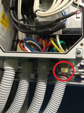
Figure 1. New EMC Gland Fitted to VSD.
They had left the pig-tail (covered in green heat shrink) and connected it to the earth terminal as seen in Figure 2 (red arrow). Why is this an issue?
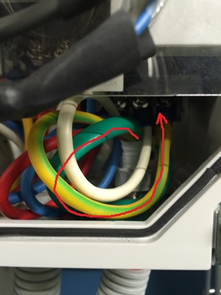
Figure 2. Pig-Tail still Present and Connected to Earth Terminal.
The fact they now have the correct EMC gland in place, which ensures a 360 º connection to the metal base plate and is connected to the rear metal back plate of the VSD (which is connected to earth) makes the pig-tail superfluous. It also potentially acts as a source of RF emission which is what we are trying to reduce. Therefore, it should be cut off when the new gland is fitted; this has now been instructed for all installation of EMC glands to VSDs.
VSD to Motor Via Isolator Switch
A further, and much bigger issue is the power cable that from the VSD to the motor via an isolation switch. Here Electro Master (subcontractor to Fredon), are still saying what they have installed is correct. Figure 3 shows the switch with plastic glands top and bottom.
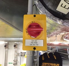
Figure 3. Isolator Switch between VSD and Motor.
When asked why they hadn’t swapped them out for proper metal EMC glands they referred us back to the their original response to the NCR stating that – what they have installed is in fact better than what the specification requested, where by relying on a compression fitting to achieve galvanic connection is a point of failure.
What Electro Master has failed to understand is the principle behind what the cable screening is actually providing. Figures 4 & 5 shows the wiring arrangement within the isolator switch.
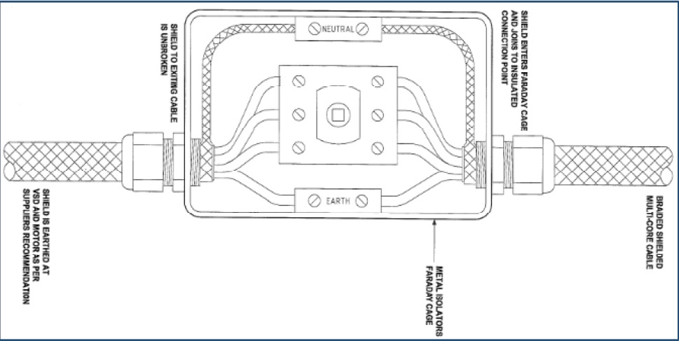
Figure 4 & 5. Electro Master’s Wiring Arrangement as per the Isolator Switch Installation.
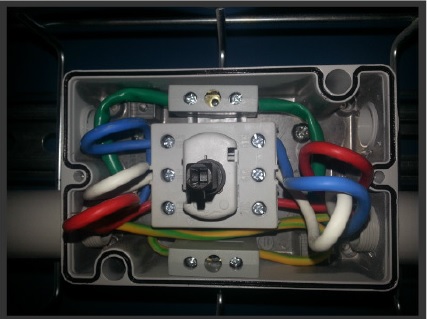
Figure 4 & 5. Electro Master’s Wiring Arrangement as per the Isolator Switch Installation.
The metal switch housing acts like a mini Faraday Cage and Electro Master were adamant that as long as the screening was continuous through the switch, by connection via the neutral terminal, then any RF emissions will be kept inside the Faraday Cage. However, this is not true due to the plastic glands used. Effectively, as soon as the screen is pig-tailed and the 3-phase and earth cables exposed, the RF emissions they produce are free to emit through the air inside the Faraday Cage which will then leak out through the plastic glands.
The solution is to install the screen being in contact with the metal housing via metal EMC glands either side of the switch and with the pig-tail cut out. This then completes the screening and the Faraday Cage will work as per the theory.
This is substantiated by the following two papers found at the links beneath:
Variable Speed Drives and Motors – GAMBICA / REMA Technical Guide.
Best EMC Installation Practice for VSDs – Technical Manager – Power Electronics.
According to the GAMBICA Technical Guide – “Where local to motor isolation is required for safety purposes, it is essential that the switch enclosure should be conductive, and form part of the “Faraday Cage” surrounding the entire PDS. This means that the cable screens should be correctly bonded/glanded to the enclosure”. As shown in figure 6.
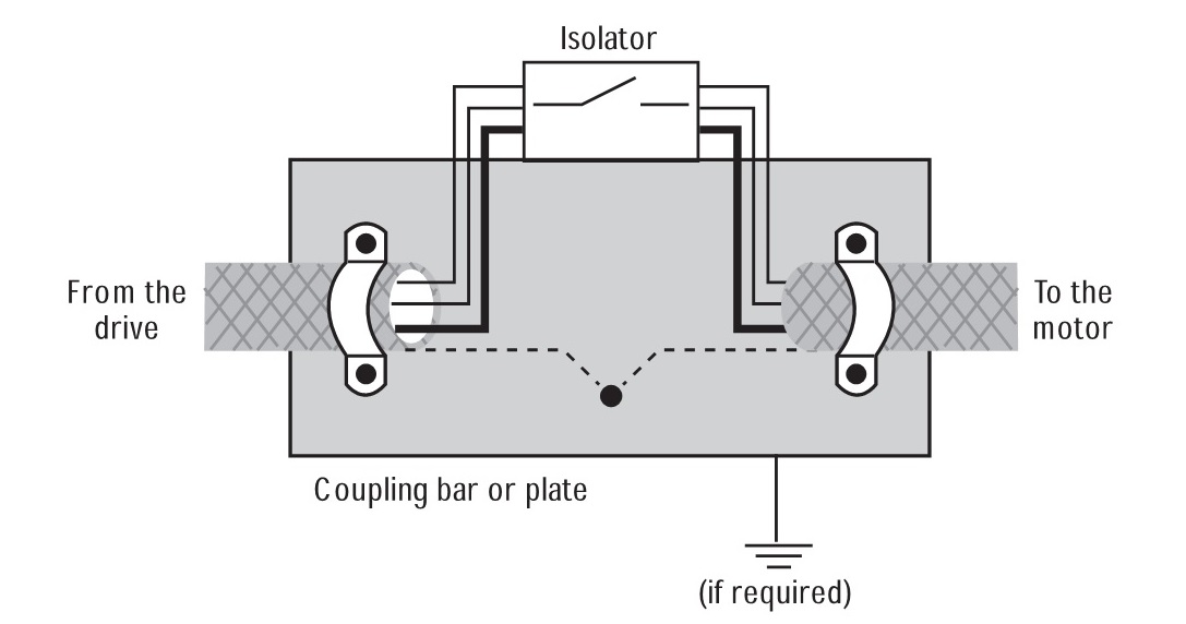
Figure 6. Arrangement for Interruption to Screened Motor Cable.
Additionally, Best EMC Installation Practice for VSDs states that shown in figure 7.
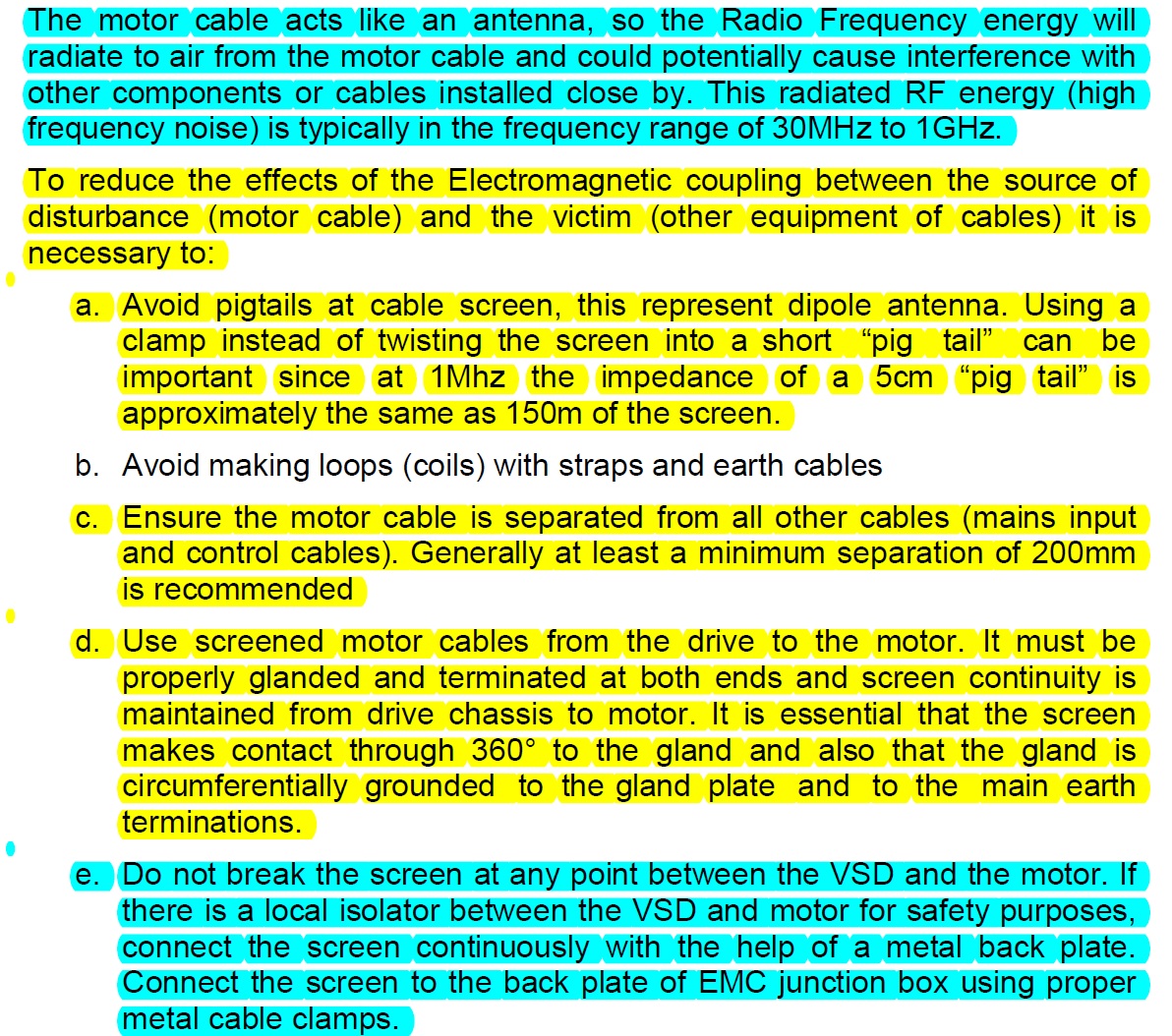
Figure 7. Extract Referring to How to Reduce the Effects if EMC.
Contradiction
However, after further research the following document was found which, to some degree, contradicts the other papers above.
Schneider Technical Note – VSDs: EMC Screen & Output Isolators.
Schneider’s Technical note states that “Common practice is to use an EMC gland to connect the shield into a metal enclosure to continue the Faraday cage, but safety requirements often mean that the enclosure must be bonded to ground at that point as well and hence compromises the EMC HF return path”. As shown in figure 8.
Figure 8. A Practical Work Around for Maintaining Safe Bonding and an Uninterrupted High Frequency EMC Return Path.
Important Notes:
- Continue the screen braid through the isolator ideally using the same braid and keeping this as flat as possible. Avoid pig tailing and/ or twisting the screen.
- The screen is not connected to the chassis or earth at any point other than at the motor and drive.
- Ideally EMC type glands should be used to bond the screen to the motor chassis
- Use the drives EMC shield Clamp to bond as shown.
This is exactly what Electro Master has installed but they have still used pig-tails which is bad practice.
Conclusion
Through reading the papers above, limiting the RF emissions seems imperative in ensuring there is a low impedance path to enable the current to return to its source. My conclusion is that the high frequency low impedance path between the VSD and motor must be maintained (by the screen) even if there are local motor isolators installed in-between. In this particular case because the VSD and motor are both grounded to earth (at each end) then avoiding a third earth connection is imperative otherwise you end up effectively splitting the cable which breaks the single faraday cage theory; the reason why Electro Master are adamant that they should not connect the screen to the metal isolation box which is earthed.
Therefore, it is my opinion that what Electro Master has installed, based on the earthing arrangements used, has met the intent of the specification. The ‘litmus test’ is the implication associated to leaked RF emissions that could cause interference with specialist medical equipment which could then potentially result in a child’s death.
Although patient safety must always be the priority, you could also consider other factors that would be a consequence from making Electro Master strip-out and install EMC glands, such as: increased cost (to Electro Master – up to $40,000) and potential time delays to commissioning.
What is very apparent is this area of electrical engineering is highly specialised and above my experience level as well as anyone else’s in the office. So although I conclude that Electro Master’s installation of the isolation switch being sound, we have and must refer the issue to NDY for them and their specialist electrical engineers to provide us with an answer for the way forward.
Oz PCH – Chatham to Perth

From this…

…to this!
Introduction
Now that the Phase 1 students have been informed of their Phase 2 attachments I thought I’d blog about my (and my wife’s) experiences on initial move out here to Perth. I actually got my wife to write this after being here for a few months so it will not discuss any John Holland work related aspects. If anyone does actually end up in Perth on a John Holland project then I will be happy to discuss any specifics separately as the likelihood of working with some of the same people is very high – there is only one new project in Perth that John Holland are currently tendering for.
Despite being the second most isolated city in the world; after Honolulu, Perth really is a wonderful place that has something to offer for everyone no matter your interests or preferred life-style. We have had a wonderful time so far and thought some of the things we have learnt in this first month may be of use to others. Firstly, there are some things you can do from the UK that will make your trip that bit easier. The main one would be to organise an Australian bank account – we went with Commonwealth Bank [they have a very handy smartphone app and have lots of branches doted around]. This can be done from the UK and all you need to do when you get here is head into the nearest branch and finalise some details. Make sure you take your passport for this as UK driving licenses and Military ID are often not accepted. [All this information and more can be found in a PowerPoint presentation on the PEW SharePoint].
Travelling
You won’t have too much choice on airlines but you will be able to decide if you would like an overnight stop. It is important to remember that unless you have children you will have to pay for this out of your own pocket. [Qantas has announced a non-stop flight by 2017, see link below, but to be perfectly honest a few hours transfer in Singapore is no drama at all and I can recommend Singapore Airlines].

Great airline and easily within the Army allowance.
Weather
We arrived in autumn [March] and the weather was gorgeous. Locals grabbing for their coats but you won’t need anything more than a thin jumper in the evenings. [Hot enough to call it a British summer that’s for sure].

Initial Stay
We were put up in Quest Apartments for the first month. It is worth doing a little research before you leave so that you can suggest where you would like to be living; coast or city, dependant on distance from site of course. We were in Scarborough (on the coast) and although it was a little far from work [I wasn’t working for the first 3 weeks] it was a lovely vibrant place to stay with plenty of restaurants and a stone’s throw from the beach. These apartments provide a charge back service so that we could eat out and charge it back to our room where John Holland picked up the bill – very handy and definitely recommended.
Driving
Although the buses and trains are relatively good in Perth it is preferable that you have a car as things are quite spread out here. There is very minimal traffic on the roads even in rush hour but you do need to stick closely to the speed limits, which are significantly lower than in the UK (on avg 50 and 60 kph on main A-roads), as the police are very vigilant and like to set-up mobile speed cameras; camouflaged and hidden behind bushes not like the easily seen yellow boxes in the UK. Make sure that you check with the car hire company [Hertz in our case] that they have your correct arrival flight times (we were delayed slightly) so after the long journey over you have a car ready and waiting for you and don’t have to wait 45 mins like we did.
Parking
Although site specific, on-site parking is between AUD $20 – $25 (£10 – £13) per day, so cycling into work was preferred and made more enjoyable by the predictable sunny weather. Perth has some great cycling paths and on rainy days there are always the buses or trains that work well.
House Hunting
Finding a house was much harder than we thought. Our biggest issue was that 95% of rental properties out here are let as non-furnished. Back in the UK we thought furnished would be much easier – but be aware this dramatically limits availability. You need to weigh-up whether you think it’s more hassle to ship furniture over/buy some when you are here and use the Army buy-back scheme or spend longer looking for a fully furnished property. We have been persistent/lucky and stuck with looking for fully furnished and have found an awesome three bedroom house 8 min walk from the beach.
Finding Work [for the wife]
Being a teacher we thought it would be easy finding work; on the contrary, it was extremely difficult but mostly due to the education system here being set-up differently and there is definitely a clique of looking after their own first. Make sure that if your partner intends to work that they do extensive research into the requirements of that profession. Bring all your original qualification documents in case you have to send off copies to prospective employers as they will have to be officially certified. There are plenty of schools though just not that many jobs. Relief work, managed through an agency, is the best foot-in-the-door way to secure a full-time position.
Fitness
If you are into fitness [which you should all be] you will be spoilt for choice in Perth. We fully intend to try everything [and have had a good stab at most things so far] and have already fallen in love with stand-up paddle boarding. [Being a tri-athlete there are some great clubs in Perth, mine being Stadium Triathlon Club. This also extends to purely swimming (my wife is a member of Claremont Masters) and cycling clubs; which are all plentiful and very well attended. To that end, if you are a cyclist or think you might like to cycle out here, and I’d suggest you do as it’s a great way to explore Perth, then definitely ship your bike(s) over. Fitness is part of the culture out here and everyone goes to bed early so they can get up early for a pre-work session; massively helped by the utter rubbish that is on what they call TV. Even at the weekend you will see a lot of people up at 0600 walking dogs, running, cycling and swimming – it literally is a Mecca for sports!].

If anyone on attachment to Oz would like any more info please drop me an email franrizzuti@hotmail.com
State to State will vary somewhat for which it will be best chatting to the others out here once you know exactly where you’re going but any general questions are very welcome.
In Other News
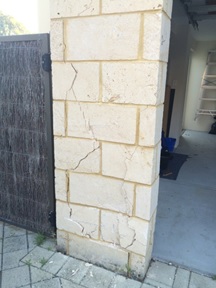
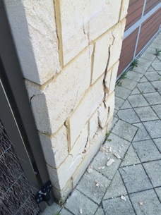
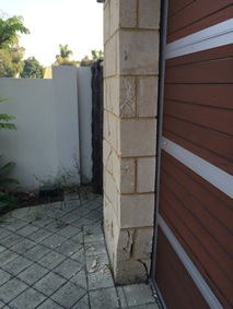
This is what happens when a neighbour reverses onto your driveway to let another car past but accidently puts his foot on the accelerator instead of the brake!
Oz PCH – Electromagnetic Compatibility Concerns.
Introduction
Within Fredon’s (mechanical installation subcontractor) scope of works, one element is the mech-elec installation works associated with Variable Speed Drives (VSDs) site-wide. After a quality review, conducted by NDY (design consultants), of the standard of installation of completed works, a number of defects were found that were felt didn’t comply in accordance with the mechanical quality specification; of note was the VSD controller cable installation. These were communicated to JHG via a Consultant’s Advice Notice (CAN), which is routine practice.
Fredon did nothing to rectify the defects relating to the VSD cable and so JHG issued an Event Notification. This consisted of a Non-Compliance Report (NCR), raised on JHG’s internal quality management system. This has significant commercial implications for the subcontractor if not resolved in a timely manner.
Issue
The NCR stated that Fredon had not complied with the mechanical specification as the current installation did not include Electromagnetic Compatibility (EMC) glands amongst other issues. The NCR also stated that any installation works completed to-date must be removed and replaced with a fully compliant installation as per the project specification.
Fredon responded as required and provided explanation, aided by technical analysis from their electrical works subcontractor, Electromaster, for their reasoning behind their actions.
They confirmed that whilst they had installed an alternative to the specification, in all cases they meet the fundamental design intent, and in some cases have improved on it.
After a number of meetings NDY stated that whilst it was noted that some aspects of the installation may not comply with the literal wording of the specification, if Fredon were to demonstrate that the installation achieved the technical intent and complied with all associated relevant Standards, then it could be possible to consider the alternative, particularly that the manufacturer’s recommendations had been met.
Technical Background
Fredon and Electromaster put together a technical response on the issues raised in the NCR, in particular, for the EMC gland issue and stated that what they have installed also complies with Australian Standard AS 61800.3:2005 Adjustable speed electrical power drive systems – EMC requirements and specific test methods.
Why is electromagnetic shielding required?
In simple terms, all electrical equipment that has current running through it produces an electromagnetic field (EMF). This field requires shielding in order so that a build-up from multiple fields don’t interfere with other sensitive electrical equipment, especially the likes of those used for recording patient’s vital stats; in a hospital this accounts for a very large portion of electrical equipment and so electromagnetic shielding is vitally important. In addition, on certain equipment like VSDs where an inverter chops up the sinusoidal waveform, inverts it and splices it back together (through switching transistors on and off at a fast rate), this creates Radio Frequency (RF) energy which can be radiated and then coupled onto other equipment’s control and supply cables through either capacitive or inductive means. It can also be conducted to other equipment through a common impedance path such as an earth connection. So, it is even more important to shield cables that come out of VSDs.
How do we shield against it?
In this case we are talking about the motor power cable that runs from the VSD to a motor isolator switch and then to the motor itself. The mains electrical power cable to the VSD, although still carrying current, is not required to be shielded as it will be at 50 Hz and thus the same as other equipment and so doesn’t pose significant interference.
To shield cables a wire braided screen is used to surround the inner core conductor. This shielding impedes both the escape of any signal from the conductor and also prevents signals from being added to the core conductor – thus completely isolating the cable (see fig 1).
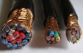
Figure 1. Typical Cable Wire Braided Shielding.
Issue Continued…
Electromaster included the manufacturer’s data sheet for the particular VSD supplied by Schneider which is used site wide; the ATV212W. They highlighted the relevant parts that confirm their installation complies with the standards. So, if NDY are content with this as mentioned then problem solved right? Not quite…
On closer inspection of Fredon and Electromaster’s technical response they highlighted the wrong VSD model and marked-up the installation guide for the ATV212H not the as-installed ATV212W.
The technical prove information was on page 52 of the installation guide, at the bottom of which it describes the ATV212W model and on the following page it clearly describes the correct cable arrangement and use of the EMC plate. Figure 2 shows the ATV212W and specifically states that the cable gland must be ordered separately as it’s not supplied with the VSD.

Figure 2. Manufacturer’s Installation Guide p.52.
Figure 3 shows the next page and highlights the need for a metal EMC gland and explains the mounting and connection required to correctly shield the cable and drive.
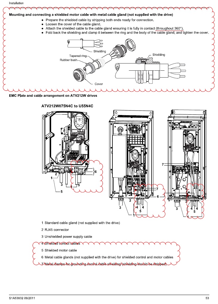
Figure 3. Manufacturer’s Installation Guide p.53.
Why was it installed incorrectly?
My view is that Electromaster have installed the VSD cables based on a combination of factors in order to save both installation time, which equals a labour cost saving, and capital costs. These are:
- Carrying out installations as per what they have previously done on other projects;
- Using standard plastic glands as these are significantly cheaper than metal EMC glands;
- Saving on labour time (approx. half) and thus reducing cost, by installing plastic glands over EMC glands, and;
- Possibly not having even read the design specification.
What is missing from their technical explanation of what they have installed is the actual termination of the motor cable into the VSD. An on-site inspection proved that they had indeed connected to the metal back plate in the VSD housing which is separately earthed, but the connection to the earth bolt was achieved by pulling the wire braided shielding round to one side and twisting it together to form what is referred to as a ‘pig-tail’ (bunched-up strands) and attached to the earth bolt (see fig 4).
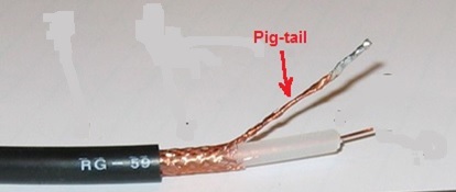
Figure 4. Cable Shielding Pig-tail – Bad Practice.
Figures 5 and 6 show the actual VSD installed by Schneider but wired by Electromaster. It can be seen in figure 6 the use of a standard plastic gland opposed to a metal EMC gland and also the shielding twisted into a pig-tail (heat shrinked in a green sheath) and connected to the ECM plate (earth). If the installation was left as it is then the pig-tail termination of the screening would mean that RF leakage could potentially escape through all the plastic glands seen in the bottom of the drive.
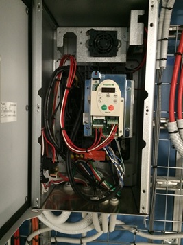
Figure 5. Schneider’s Installed VSD.
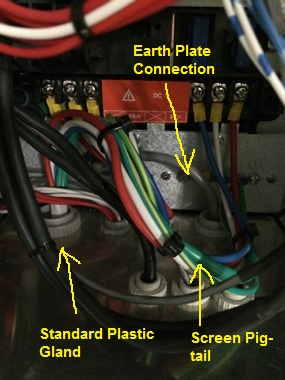
Figure 6. Electromaster’s Wiring of VSD Motor Cable.
The issue with what Electromaster has done is they haven’t completely screened the cable through 360 º, like the examples in figures 7 and 8 show.
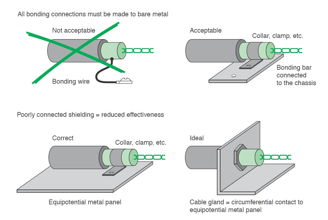
Figure 7. Schneider Electric Earth Connection of Shielding.
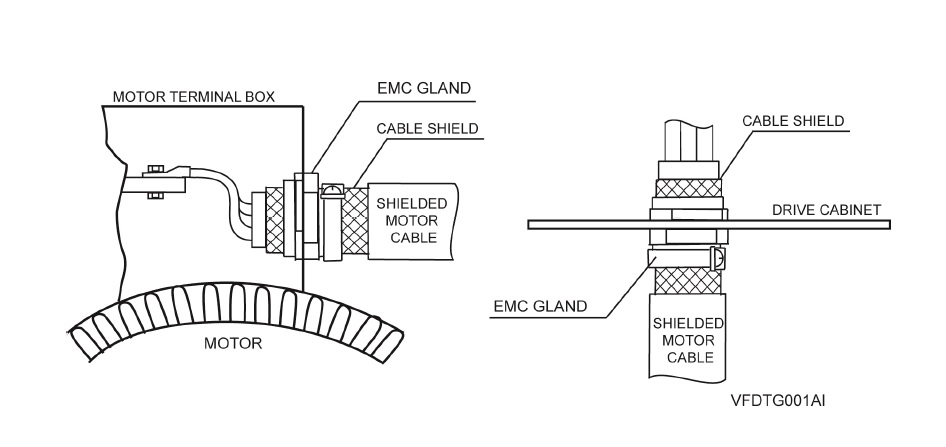
Figure 8. Power Electronics Earth Connection of Shielding.
The reason the lack of 360 º screening is such an issue is that when dealing with high-frequency electromagnetic radiation from an Alternating Current (AC) source it becomes distributed within the conductor where the current density is largest, near the surface of the conductor, and is known as the ‘skin effect’. The electric current flows mainly at the skin of the conductor which causes the effective resistance of the conductor to increase at higher frequencies. Therefore, RF leakage from any unshielded portion of cable can be quite high.
A quick Google search also reveals that pig-tail terminations for cable shielding is a big ‘no-no’. Even if the pig-tailed termination is inside a metal housed VSD (mini faraday cage) then technically the RF can’t escape as long as a metal gland is used. However, Electromaster used plastic glands and so this presents a clear path for any RF leakage.
The Design Specification Intent
The method behind using a metal EMC gland with a metal plate/VSD housing is that the VSD housing acts like a mini faraday cage with a separate earth cable running to ground. Where the cable enters the VSD it is secured in place by the EMC gland with the cable shielding pulled back on itself and the gland clamped around it making a 360º connection to both the shielding and the VSD housing.
The design specification explicitly says that:
Terminate screened power cables at each end in EMC glands to ensure circumferential connection of the screen to earth. Earth the screens of thermistor sensor and motor lockout cables at the converter cabinet utilising metal cable clamps for each cable fastened to an earth bar installed within the cabinet for the purpose or with EMC glands secured to an earthed gland plate externally to the cabinet, as specified by the manufacturer.
Motor isolators shall be 4-pole, key lockable mounted in a die cast alloy enclosure. The isolators shall switch the motor power and control circuits simultaneously. Cable entries shall be fitted with EMC cable glands and earth bushes suitable for the cable types connected. The earth bushes for each circuit shall be connected together with 6 mm2 cable to maintain continuity of screening of the power and control cables.
Resolution and Possible Fixes
One possible solution could have been to swap the plastic glands for metal ones as this could theoretically be adequate. However, Electromaster and Fredon would need to back-up this installation with technical proof of this which may be difficult as all reports on ‘best EMC installation practice for VSD’ state that the use of pig-tails is prohibited.
“A screened cable gland suitably designed and sized for the screened cable type used should be fitted at the motor end. Do not wind the screen into a “pigtail” and terminate under the earth terminal within the motor terminal box. Terminate the earth conductor(s) to the motor earth terminal(s) located inside the motor terminal box. When installing the SD700 directly on the wall (no additional enclosure) a screened cable gland suitably designed and sized for the screened cable type used should be fitted at the SD700 gland plate. Do not wind the screen into a “pigtail” and terminate under the earth terminal within the SD700 terminal box. Terminate the earth conductor(s) to theSD700 earth terminal(s) located inside the terminal box” (Power Electronics 2013).
Therefore, they need to comply with the design specification which is to use specific EMC glands.
So What?
There are approximately 400 VSDs site-wide with motor cables terminated incorrectly. These therefore must be re-worked as JHG have alluded to in their NCR. This has been confirmed by NDY and so Electromaster, via Fredon, must now conduct the re-work.
Costs
Based on the RS catalogue and list price, which clearly a subcontractor will get at trade but fine for comparison reasons.
Capital Costs
The capital costs of switching the glands alone would be in the region of $20k (£10k).
$25 per EMC gland x 800 (2 glands per VSD) = $20k
$1 per plastic gland x 800 (2 glands per VSD) = $800
A difference of $19,200.
Labour Costs
2 hrs per VSD at $65 – $80 per hour = $130 – $160 per VSD x 400 VSDs = $52k – $64k (£26k – £32k).
Total Costs
$72k – $84k (£36k – £42k).
Conclusion
From this example I have learnt a number of points:
- Subcontractors will, unless very diligent, usually default to conducting works how they have always done so on past projects.
- Due to point 1, subcontractor’s work must always be quality checked.
- Subcontractors will try and convince you that what they have done is in accordance with the specification. In providing technical evidence to back-up their installation, if an alternate method had been used, they will may well be proving only half the truth and purposefully omit defective practices.
- Due to point 3, subcontractor’s evidential explanations should always be scrutinised for accuracy.
- In an office block the leakage seen could probably be tolerated but the key issue in this project is that the building is a hospital and if there’s ever a place you don’t want to cause RF interference it’s in a hospital.
In Other News
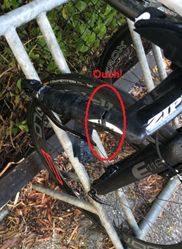
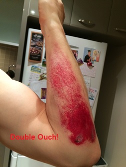
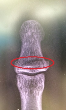
My Ironman (IM) trg has taken a bit of a hit. In a build-up half IM race I decided to trow myself off my bike but not forgetting to do my best superman impression before hitting the deck pretty hard. My initial annoyance was the damage to my bike; carbon fibre is costly! Although pretty battered, bruised and scratched (mainly to my pride), in good old Army fashion, I soldiered on finishing the remaining 20km of the bike leg and the 21km run. Post-race clean-up and a trip to A&E the next day confirmed I had actually broken my thumb; I did feel a fair amount of pain whilst trying to change gear – now I know why.
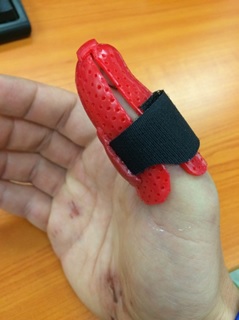
What impressed me most during my treatment was the thermoplastic thumb splint (available in a choice of colours) complete with water friendly Velcro securing strap, although I’ve already got some design mods in mind for version two. It means I can still compete in my next half IM trg race in 2 weeks’ time before the thumb is estimated to be fully healed 6 weeks from now.
Below are some pics…

Oz PCH – Commissioning of Chilled Water Supply from Central Energy Plant.
Introduction
This blog follows on from my previously explained, Chilled Water (CHW) pipework flushing blog. It takes the discussion further, explaining the CHW system, commissioning and project wide examples of applications including problems faced.
The CHW System
Fig 1 shows the main plant: flow and return connection to CEP CHW, the mixing decoupler, flow meters, the pump sets in an N + 1 arrangement (n = 4 pumps duty), the four flow and return legs that feed various risers and the critical to life pump sets and flow and return legs.

Fig 1. Plantroom 10 (Basement) CHW Equipment Layout.
The total flow rate for all four legs is 605.1 l/s. Fig 2 shows the N +1 pump sets with 4 x duty pumps (rated at 125 l/s each) producing 500 l/s; the 105.1 l/s delta (17%) is for system diversity.
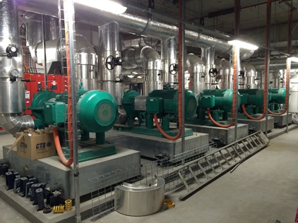
Fig 2. Plantroom 10 CHW Pump Sets.
The CEP design flow temp is 7 °C and return is 14 °C.
The following main equipment is fed by the CHW system:
Central Computer Room 2 (CCR2) – This is the main communications hub of the building and houses sensitive electronic equipment, such as the 67 x computer data racks, which requires constant cooling. At full operational load the data racks will push out 450 kW of heat load. The design incorporates in-row cooling with a ‘hot aisle’ containment system (see figs 3, 4 and 5) using distributed Computer Room Air-Conditioning (CRAC) Units (stand-alone Fan Coil and Condensing Units) integrated into a false floor. Humidity is controlled locally and there are also self-protection measures such as a pro-inert fire suppression gas deluge system with purge ventilation, anti-static flooring and an Uninterruptable Power Supply (UPS).
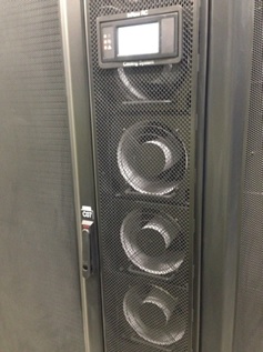
Fig 3. CCR2 Data Rack In-Row Cooling.
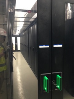
Fig 4. CCR2 Hot Aisle Data Racks.
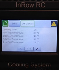
Fig 5. In-Row Cooling System Control PLC.
Field Communications Rooms (FCR) – Data from CCR2 feeds each of 37 x FCRs via a combination of copper and fibre optic connections, which also requires constant cooling provided by dedicated CRAC Units; fed by CHW from CEP. The FCRs, like CCR2, are critical to building functionality managing items such as: Building Management System (BMS), security, fire protection, nurse call, lifts, CCTV, Automated Guided Vehicles (AGVs), medical gases and the Health Integrated Network systems.
UPS Rooms – There are 3 x UPS Rooms each with 2 x CRAC Units (duty and standby).
MRI Machines – The 2 x MRI machines are hydraulically separated by plate heat exchangers with the secondary circuit pumps located in PR 6, see fig 6.
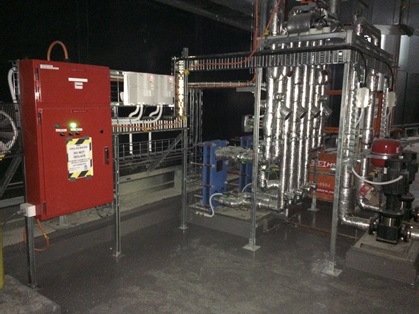
Fig 6. MRI Plate Heat Exchanger and Pump Set.
AHUs – There are approx. 82 x AHUs across 9 x Plantrooms (PR). These use the CHW to run through the coils used for air-conditioning.
Increased System Volume Issues
In normal circumstances commissioning of a piped water system would occur once all installation is complete. However, on the PCH project that was not possible due to the Client’s requirement to energise and therefore provide cooling to CCR2. The CHW feed from CEP was opened but because the initial heating load was very small, keeping the CHW flow and return permanently open would mean the return temp to CEP being around 8°C; too low. This gave a very small ∆T (7°C flow and 8°C return) and the concern was this would cause the CEP BMS to reduce the cooling required by the chillers thinking it’s not required and potentially turn them off or reduce their cooling. This would adversely affect other areas of the QEII Medical Centre, whose heating loads are at normal operating capacity.
In order to avoid this the PCH site controls the volume of CHW through; enough to provide sufficient cooling for current heating loads via the CEP Isolation Valves (IV). The design intent is to permanently keep the CEP IVs open to allow the CHW to flow from CEP around the PCH site and back again, closing the loop.
The design intent cannot be achieved until PCH sees ‘normal operating’ heating loads to avoid the return CHW being too cold; it should be around 14°C to avoid the above issue. This heating load will not be seen until all external facades are in place, the building has been completely sealed to the outside elements and all heat generating equipment has been installed like: lighting, AHU fans running etc. Only then will the AHUs be demanding sufficient CHW in order to maintain comfortable working conditions. Until this time the CEP IVs will be left in a controlled open/closed when necessary state with the decoupler loop valve left in the open position to allow what CHW has been let through to circulate round the PCH CHW system.
Periodically, when the PCH CHW temp begins to rise, the CEP flow IV is opened (operated by temp sensors that control the motorised valve) for a brief period to allow a slug of 7°C CHW through and similarly the return IV opened to allow a slug of 10 – 14°C CHW back to CEP. This procedure is fine in theory but in practice the CEP IVs are not meant to be operated at such regular intervals as they are designed to be either open or closed and not to regulate flow.
At present, because the BMS is not yet fully operational, the basement services co-ordinator has to manually set the return flow trigger temp (set at 10°C) to allow a slug of CHW through from CEP. This trigger temp is set based on the cooling load required for the equipment from across the building; which at present is very low. However, there are certain critical areas that must stay cool but have been experiencing high temps lately. These are the FCRs and UPS rooms.
The issue currently seen is caused by the following factors:
Due to a number of plantrooms having completed their commissioning they were ready to open-up to CEP via the central services risers. As they were opened the CHW system volume increased and with that the system pressure dropped. This meant that the flow rate was too low and the CHW would have gained too much heat by time it reached the FCUs (even with lagged pipes). The knock-on effect was that the FCRs and UPS rooms were struggling to keep cool as the FCUs / CRAC units were unable to provide sufficient CHW due to the reduced system pressure. An additional reason why the FCRs were getting warmer was because the building fabric is now better sealed and climate conditions are changing; getting hotter outside.
Solution
The solution is easy and in order to increase the flow rate and thus increase the system pressure the mechanical pumps need to increase their speed. Currently there is only one pump running at 40 Hz. When it is manually increased to 50 Hz (its design maximum) and if the system still requires more velocity pressure, an additional pump will be run-up to maintain this; found from the equation derived from Bernoulli’s: Pv = ½ ρ c2.
At present until the BMS is fully operational, where two pumps at a time will run simultaneously; a second pump will have to be run-up manually. This will allow commissioning works to continue; balancing of individual plantrooms and thus not hold-up subsequent integrated commissioning or the project as a whole. The fully operational BMS is around three weeks away and that is a lot of time to lose to wait for the perfect control solution. Therefore, the interim measure requires careful co-ordination of the requirement to increase pump speed matched to the increasing system volume (from opening subsequent plantrooms to CEP CHW) in order to maintain system pressure. It also requires a robust means of monitoring temp control.
Co-ordination Requirements
It was evident that from the questions I was being asked by the installation services co-ordinators, that there was no clear methodology or plan in place in which to open-up subsequent plantrooms to CEP CHW in a sufficient way that would not cause the system to ‘fall-over’. In particular, my concerns were that critical equipment reliant on a CHW supply could become damaged, costing huge sums of money to replace, such as: MRI machines, UPS and FCR equipment.
So what part did I play in co-ordinating the effort to resolve these current issues?
The thing that was most obviously about the CHW system was that there were many people involved who were working in their own little silos with little communication happening. The first thing I wanted to achieve was to establish the single point of truth and from a commissioning team perspective, understand the system and what issues we were facing. This was achieved through an initial mtg with all key players: design consultant, construction subcontractor, controls subcontractor and us the managing contractor.
The mtg was successful in a number of ways, most notably was a number of action points for the subcontractors to answer and allow us to co-ordinate accordingly thus ensuring the integrity of the system and that critical areas did not get too warm.
In practice the co-ordinated plan didn’t quite survive first contact. The plan was to open up PRs 4, 5, 6 East and 8 to CEP. The objective was to open them all but maintain the current flow rate knowing that critical equipment was stable in a ‘happy’ state. We started off by measuring the flow rate to one of the FCRs in PR 6 which was 0.375 l/s, 140% of design flow rate of 0.27 l/s. This was with 1 x pump running at 46 Hz.
We then ran up a further 2 x pumps and backed-off the first pump to match them. This was an iterative process until we got to a comfortable flow rate in PR 6. This was 86% of 0.375 l/s which equated to about 120% of design flow rate. All 3 pumps were running at 40 Hz.
We then opened-up PR 4 and went back to PR 6 to measure the % drop. We were at 81% of 0.375 l/s and content with that flow rate. All 3 pumps still at 40 Hz.
However, PRs 5 and 8 remained closed-off to CEP as I felt the condensate drains and some un-lagged pipework not being complete could cause condensation issues. Once these are complete these can be opened.
We also witnessed the CEP CHW IVs opening and shutting letting through CHW as required based on the return temp control. Therefore, we were content if the temp rises then CEP will restore it.
All pumps were still only manually controlled and would require the same above process for energising the remaining PRs to CEP.
It was found that the flow temp was slightly higer than design and should FCRs, CCR2 or MRI temp increase then we should first look at this. Currently with the mixing occurring through the decoupler we are seeing a flow temp of around 10 – 11 °C. This is more likely the reason why areas are getting too warm rather than pressure drops or reduced flow rates.
The position we want to be in is have PR 1 flushed and opened to CEP. This being the index run throughout the building means we can set the pumps to monitor the differential pressure at that point. This is so that no matter if we open-up additional PRs (increasing system volume) or if we close-off PRs (reducing system volume and thus potentially causing a pressure build-up in a closed head scenario) then the controls can adjust accordingly in dynamic fashion and remain stable.
What did I learn?
- If you are at the point where speaking to different parties gives you the feeling that the right hand isn’t talking to the left then you need to set up a mtg sit everyone down and systematically run through what’s what, where you are currently at and where you want to get to.
- Old school still works. I’m referring to the simple but very effective method of printing off A0 dwgs and physically highlighting the pipe runs using a different colour to distinguish its status: flushed and cleaned, opened to CEP CHW, proportionally balanced etc. It provides a dynamic way of statusing the progress of a system when dealing with a complex building with nine plantrooms over nine floors.
- Condensation is a real concern as proved by a number of valves not being lagged before CEP CHW connection as shown in figs 7 and 8.
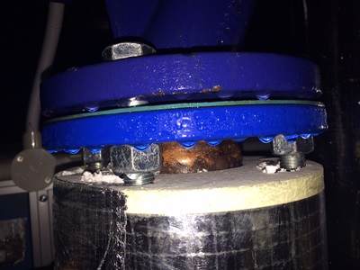
Fig 7. Condensation Formed Drops on Valves.
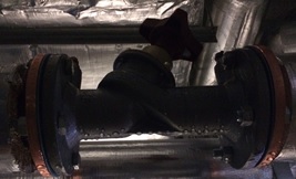
Fig 8. Condensation Formed Drops on Valves.
4. A slightly annoying learning point is that no matter how many repeated verbal and written communications are made, subcontractors still ‘do their own thing’. An example of this was where the condensate drains not being correctly installed before the AHU CHW coil IVs were opened, causing the inevitable ‘sweating’ (condensation) to drip off the coil into the condensate collection tray through the drain pipe then onto the plantroom floor. The subcontractor, Fredon, said the spill on the floor was from when the engineer replaced the clear plastic section in the drain pipe to copper, as per fig 9. But I wonder how much trouble it would have been to use a receptacle or even just tissue paper to mitigate getting the floor wet? And, how do they explain opening up to the coil with the obviously missing section of pipe that should continue to the tundish in fig 10? This leads on to valuation payment claims from the subcontractor being reduced.

Fig 9. Condensate Drain Replacement.
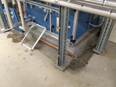
Fig 10. Spot the Obvious Issue?
5. Although I am a member of the commissioning team, I have come to realise that you can never truly get away from construction/installation issues. Sequentially, the installation must be complete prior to commissioning activity so inevitably it falls to us to drive construction completion in order to stay on track with our commissioning programme.
In Other News
The British Defence Advisor to Australia, Commodore R L Powell OBE MA MSc RN, was visiting Perth and requested the presence of those on military exchange programmes.
There were only three of us Brits meeting the 1-Star, a RN Officer working at Garden Island (a nearby Naval Base), a SBS Warrant Officer working as the UK LO to the Australian Special Forces based just up the road at Campbell Barracks, and then myself.
The visit was pretty low-key with the Attaché just asking us how we were all getting along on our respective programmes and if we had any issues in moving out here. He then spoke a bit about ongoing projects from a relationship with Australia perspective. This was all good background info and sounded quite interesting, especially the fact his post out here is a 4 year tenure – nice if you can get it, oh and have promoted to Brigadier – no biggy!
Oz PCH – Bean Counters Hard at Work.
A few weeks ago whilst setting up for my weekly commissioning mtg I noticed that the projector wasn’t working. This is one of only two projectors JHG have in K Block (project office) and they pretty much get hammered all week; so no surprises that one would give up the ghost at some point.
However, two things struck me as a surprise, firstly was that the projector had clearly not been working prior to my mtg and so had broken on ‘someone else’s’ watch; the assumption being, that particular ‘someone else’ had reported it in order to get it fixed/replaced – sadly not the case. This is a clear example of bad admin/slopping the shoulder, so when I asked one of the services co-ordinators to report it, it was the first HR at heard of it.
The second surprise was much more shocking. After HR had put a request in to the IT dept, which were apparently absolutely useless, all they could come back with was ‘we cannot provide you with a spare and suggest you might be able to borrow one from Head Office but they have no spare either’. So how about purchasing a new one? Accounts won’t approve purchasing another one this late into the project – really, really!
A quick google search for a similar standard model of projector found this for $800 approx. £400:

And there are cheaper ones at around $600.
I could think of lots of examples where this project is wasting that sort of money and it’s not even like it has to be purely associated to the project as it can be reused for subsequent projects to come.
So What?
Does this mean Friday beers and pizza will be stopping????
We will just have to make-do with the one we have, although it has already caused issues and what happens when that one decides to break?
I may approach our services director and see if he can purchase one independantly thus circumventing the IT dept.
In Other News
It’s the Aussie Footie League (AFL) grand final this weekend with the local Perth team, the West Coast Eagles, well up for it – Come on the Eagles!

Oz PCH – Helicopter Noise Attenuation.
This pic is to entice the civils to read my blog…more on this at the end.
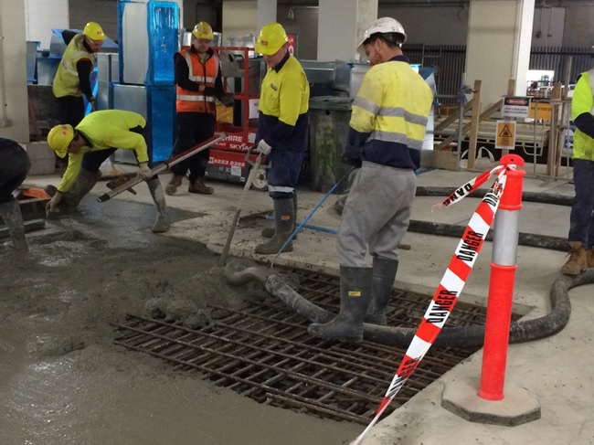
Fig 1. Concrete Pour in the Basement.
Introduction
This blog aims to discuss the potential issue of helicopter noise being carried throughout the building using the ductwork as a noise passage/channel. It also covers the attenuation used for the back-up diesel generators.
Problem
The helicopter pad was procured as a packaged unit but there seems to be a scope gap for ownership with its commissioning. That aside, the acoustic consultant for JHG stated a helicopter using the HLS (red line in fig 2) passes directly over AHUs housed in two non-acoustic out-houses (yellow line in fig 2) and produces noise levels of around 105 dB(A) as a point source. The (A) refers to the A-weighted sound pressure level which approximates the human ear’s sensitivity to sounds of different frequencies. Without this filtering, calculated and measured sound levels would include sounds that the human ear cannot hear, such as dog whistles (high frequency) and sounds made by large buildings with changes in temperature and wind (low frequency).
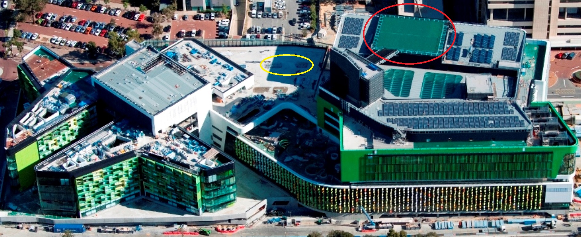
Fig 2. Aerial View – HLS (red line) AHU Out-houses (yellow line).
For comparison table 1 indicates where 105 dB(A) sits amongst other familiar sounds.
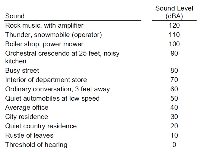
Table 1. Common Sounds on the A-Weighted Decibel Scale.
These particular AHUs, supplying conditioned air to the Theatre Department, have been placed outside on top of the plantroom as they wouldn’t fit inside due to layout design changes. This places them in close proximity to the rooftop HLS and are only covered, for weather protection reasons, by a non-acoustic out-house structure. Fredon, who are the plantroom mechanical fit-out subcontractors, have stated that there may be an issue with sound levels in the Theatres and that they have to conduct an assessment of the noise levels produced by a visiting helicopter to determine how much sound will travel down the air-conditioning ductwork and if they comply with the performance standard at the outlet grills.
So What?
Fredon were aware they had to conduct their own acoustic performance tests, highlighted at tender, as they knew a HLS was a design package; the situation now becoming more problematic with the re-location of the AHUs outside of the plantroom. Fredon should have factored-in the acoustic performance testing when the re-design took place instead of leaving it till now, once the ductwork installation is complete.
Solution and Possible Implications
They now need to conduct the acoustic performance test and if they don’t comply they will have to fit attenuators into the ductwork in order to reduce noise travel, commercially this will be at Fredon’s expense but could potentially hold-up commissioning and may incur delay claims from JHG. The impact could be reduced if they can fit attenuators in the plantroom directly below the AHUs on top and this would cause the least pain in terms of cost and time delays but it will depend on how much attenuation is required and how congested the plantroom is already; the alternative being to fit them further downstream in ceiling voids, that are already closed up, but this is something we and Fredon would want to avoid if at all possible.
Fredon are waiting for confirmation of the noise criteria from the design consultants NDY before continuing with the test. NDY are waiting for the client to sign-off a design departure for the criteria laid out in table 2 (red box).
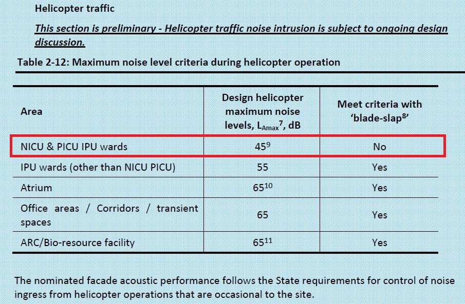
Table 2. Max Noise Level Criteria during Helicopter Operation.
NB:
7 Typical values generated by helicopter movements along defined flight paths.
8 ‘Blade Slap’ is the sharp cracking sound from helicopters, typically occurring with turns, shallow descents and flare approaching a hover.
Performance criteria are provided in Table 1 on the basis of data and modelling obtained with blade slap characteristics included.
9 Assessed in terms of the continuous equivalent LAeq level. To comply with 45dB LAeq(15 mins), the LAmax (slow) is to be less than 55 dB(A) or it can exceed LAmax (slow) 55 dB(A) for 6 minutes per hour. Further LAmax should not exceed 65 dB(A) at any time.
How Attenuators Work (Simplistically)
In simplistic terms, when fitting an attenuator in line with ductwork it requires a larger space than just the original ductwork. Fig 3 shows this including the tapered sections either side of the attenuator.
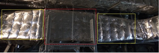
Fig 3. Attenuator. Red box showing the attenuation section with the two yellow boxes showing the tapered sections.
Theoretically and in practice an attenuator works by the noise being absorbed by the acoustic filler (wool mixture) in the solid sections with gaps between to continue to allow air flow. Due to the sections taking up space (around 40%) of the duct volume, the air velocity increases. This increased velocity creates its own noise termed ‘regenerated noise’. As long as the net noise level has reduced it is considered worth doing but engineers can get caught in the trap of the law of diminishing returns due to the increased pressure losses caused by the reduction in volume. This is caused by a pressure change/differential between the point before and after the attenuator. This results in second and third order effects of requiring a higher fan speed to overcome the pressure losses and then requiring a bigger fan motor which uses more electricity. A way to resolve this is by maintaining the pressure over the attenuator which can be achieved by ensuring the attenuator is the same volume as the ductwork leading up to it. Due to the space taken up by the acoustic filler sections inside the attenuator, means that the overall dimensions of the attenuation section has to increase, as shown in fig 3. Sometimes this causes issues if there is limited space in a ceiling void.
A Different Example – Diesel Generator Noise Attenuation
I had a look around one of the 3 x 1.25 MVA back-up diesel generators to investigate its noise attenuation design.
The generators, manufactured by Cummins, are housed in individual acoustic and weather protected containers.
Inside the container, at both ends, are the attenuation sections as shown in fig 4. These are vertical sections (red line) with a permeable membrane filled with acoustic noise damping wool. At this end outside fresh air is being drawn in (blue arrows) by the generator radiator fan but the noise is escaping (yellow lines) through the gaps between the acoustic sections.
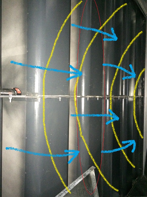
Fig 4. Generator Attenuator Section – Radiator Fan End.
Fig 5 shows the incoming outside air (blue arrows) and the noise path (yellow lines) taken as it bounces between the two acoustic sections losing noise as it passes through the acoustic material and finally out the louvres at the end.
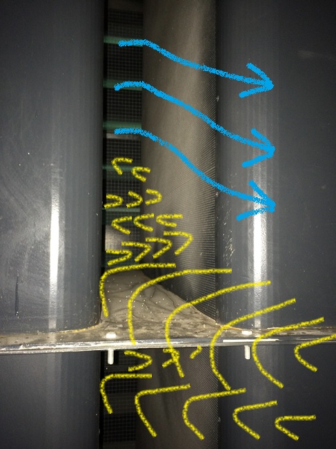
Fig 5. Generator Attenuator Section Working – Radiator Fan End.
The capping louvers at the container end have acoustic foam attached to the underside of each horizontal louver and so also acts to reduce noise coming out (yellow lines in fig 6) but allows fresh air to be drawn in (blue arrows).
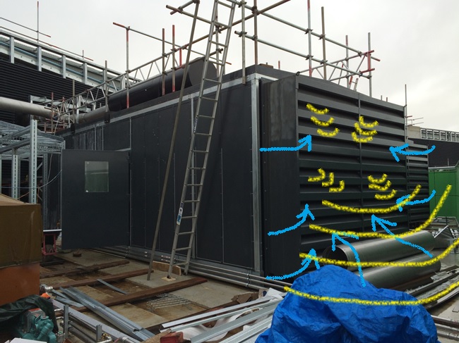
Fig 6. Generator Louvre End Capping.
We are currently waiting for the generators to be run-up and tested with the installed fuel supply system and for all three to be tested for load sharing as part of system commissioning. Until that time we cannot fully test the acoustic noise levels produced.
Useful References
BSRIA – A Guide to HVAC Building Services Calculations (2007) (second edition) p.125 – 133, describes the acoustic calculations required in design, in particular ductwork noise transmittance.
CIBSE Guide B – Heating, Ventilating, Air Conditioning and Refrigeration (2005) – Section 5 Noise and Vibration Control for HVAC p. 5-1 to 5-22.
In Other News
For the civils, the below pics are from the final basement concrete pour filling the ground slab where one of the tower cranes once stood. Fill your boots to ask questions but I most likely won’t know the answers…I just took the pictures!
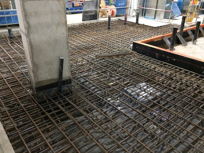
Rebar, Form Work and Tower Crane Bearing Pile
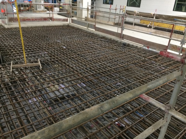
Rebar and Tower Crane Bearing Pile
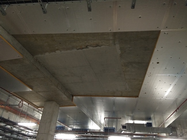
Previous above Slab Aperture for Tower Crane
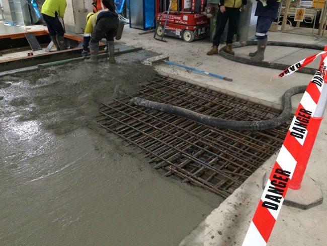
Concrete Pour

Finished Pour Levelled
And finally…speechless!

Oz PCH – Ductwork Leakage Pressure Testing.
Introduction
As part of the commissioning of the Air-Handling Units (AHUs) one test is to ensure any air leakage, which results in loss of pressure, is kept to within allowable maximums. This blog briefly discusses a leakage test I witnessed for one of the High-Efficiency Particulate Arrestance/Air (HEPA) filters in the operating theatre department.
In the application of theatres the HEPA filter is part of the laminar flow hood situated directly over an operating table. Here the filter’s minimum resistance (pressure drop) to airflow is specified at around 300 – 400 Pa at 370 l/s flow rate. The effect felt by the patient undergoing an operation is one of a soft blanket of very clean air.
HEPA Filter Function
HEPA is a standard and not a type per se, set by the United States Department of Energy (DOE) and is only awarded to filters that satisfy certain standards of efficiency. To qualify as HEPA an air filter must remove 99.97% of particles that are of 0.3 micrometers (µm) in diameter.
HEPA standard filters are composed of a thin mat of randomly arranged fibres. Fibres are typically between 0.5 to 2.0 µm and made of fiberglass. The air space between fibres is typically > 0.3 µm and the common assumption that fibres smaller in diameter can pass through (like a sieve) is not true. HEPA filters are designed to target much smaller particles which get trapped, by sticking to the fibres, through the following mechanisms:
- Interception. Where particles following a line of flow in the air stream come within one radius of a fibre and adhere to it.
- Impaction. Where larger particles are unable to avoid fibres by following the curving contours of the air stream and are forced to embed in one of them directly; this effect increases with diminishing fibre separation and higher air flow velocity.
- Diffusion. An enhancing mechanism that is a result of the collision with gas molecules by the smallest particles, especially those < 0.1 µm in diameter, which are thereby impeded and delayed in their path through the filter and raises the probability that a particle will be stopped by either of the two mechanisms above; this mechanism becomes dominant at lower air flow velocities.
Figure 1 shows a typical filter layout/construction with pictorial explanation of the three types of filtration; interception, impact and diffusion.
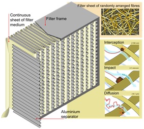
Figure 1. HEPA Filter Layout/Construction.
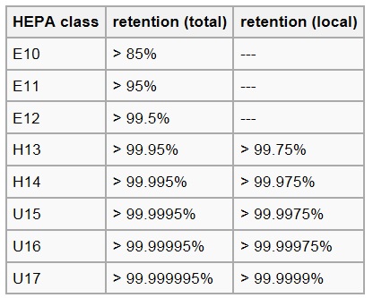
Figure 2. HEPA Filter Classification.
Figure 3 shows the laminar hood above the operating table in the operating theatre.
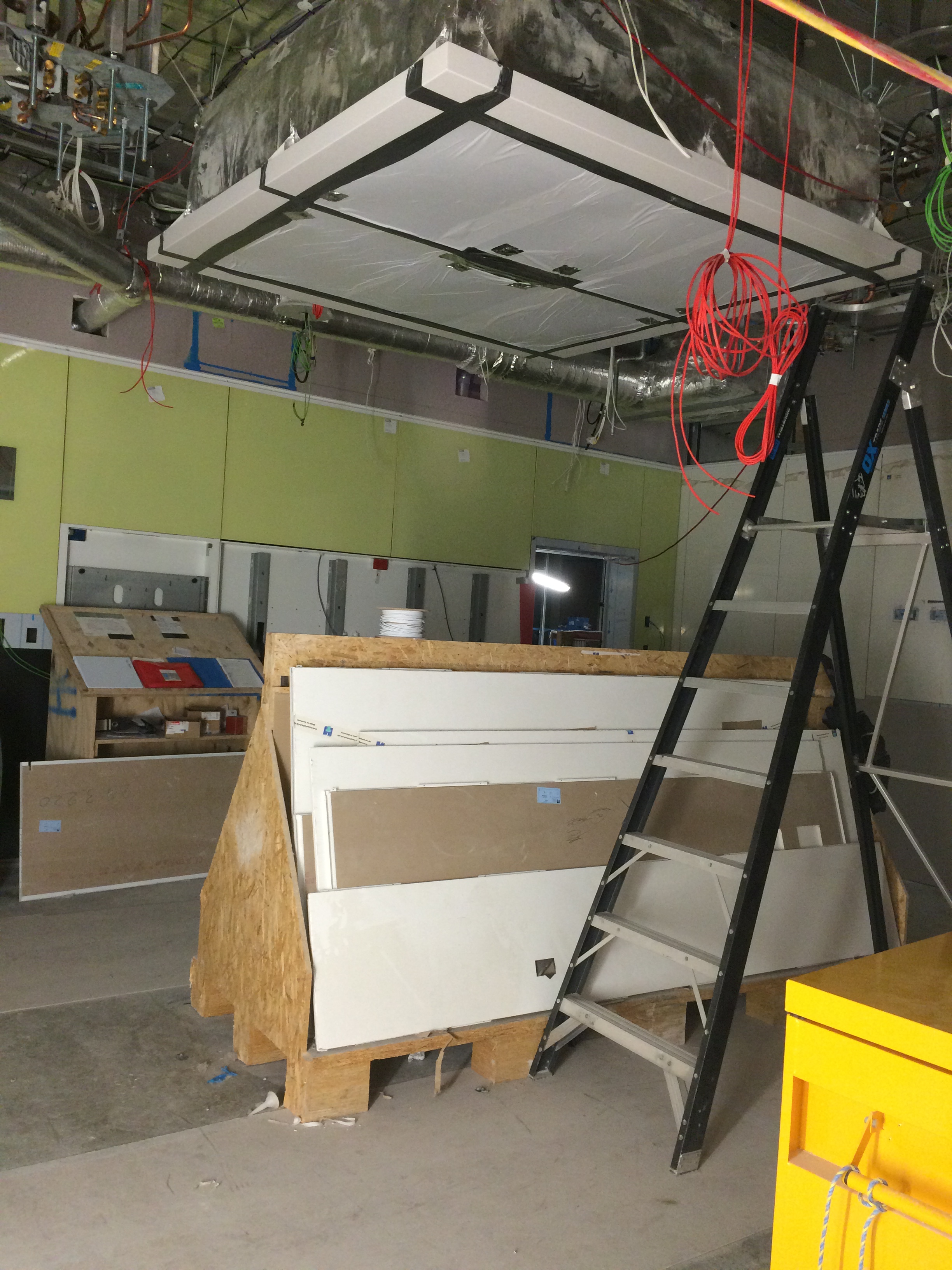
Figure 3. Laminar Flow Hood in Operating Theatre.
Fredon test to AS 4254 – Ductwork for Air-Handling in Buildings, which stipulates:
2.2.4 Air leakage
Duct systems with a capacity of 3000 L/s or greater shall be tested for air leakage at a static pressure of a minimum of 1.25 times the calculated design operating pressure in the tested duct section. Leakage shall not exceed 5% of the design air quantity for the duct system.
The systems in theatres are not greater than 3000 l/s of air so there was no actual requirement to test but Fredon conducted them regardless.
Leakage Test
As per the AS, 1.25 x our design pressure gives just below 750 Pa. The design pressure being the pressure produced by the fan plus any losses created by the Fan Coil Units/filters in the AHU (about 150 – 200 Pa) totalling around 600 Pa. The test achieved this and further more we were assured by Fredon that under normal operating conditions the duct would not reach this pressure.
The ductwork in question was one of four terminals branching off a single AHU (see fig 4). Each terminal has a flow rate of 370 l/s x 4 = 1480 l/s. Testing for a maximum of 5% leakage at a pressure of 750 Pa gives 5% of 1480 l/s = 74 l/s.
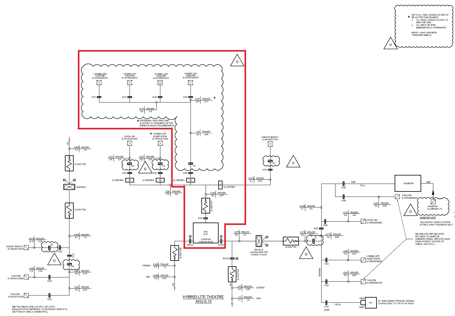
Figure 4. Schematic of AHU 6.10 showing 4 x Theatre Laminar Flow Hoods.

Figure 5. Leakage Test Sealing Plate and Hose.
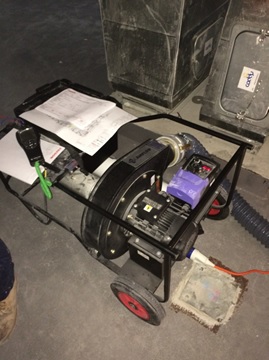
Figure 6. Leakage Test Rig.
Potential Issue
There was a potential issue raised as NDY, design consultant, stipulated in their design specification that ductwork should be tested to CIBSE standards – which refers to Heating and Ventilating Contractors’ Association (HVCA) DW/143 Ductwork Leakage Testing. Here it states that the system leakage loss for Class B medium pressure ductwork, under operating conditions, should not exceed 3% of the operating pressure.
Therefore, 3 % of 1480 l/s = 44.4 l/s.
So, 13 l/s is still well within the CIBSE/HVCA limits.
There was also a further potential issue in that the client may have wanted the test pressure to be the maximum for that class of ductwork, which is 1000 Pa operating pressure. As Fredon were adamant that the system would never operate above 750 Pa they were reluctant to test to this higher pressure.
In order to ascertain if the leakage would still be within the maximum limits due to the increased pressure a calculation could be conducted. There is no precise formula but it is generally accepted that leakage will increase in proportion to pressure to the power of 0.65 (HVCA 2000). This is due to leakage from ductwork occurring at the joints and seams and is therefore proportional to the total surface area of the ductwork in the system.
Therefore:
(1000/750)^0.65 = 1.2056.
1.2056 x 13 l/s = 15.76 l/s (for 1000 Pa). So, 15.76 l/s of 1480 l/s = 1.06% – still well within the 3% limit.
As it turned out the client did not request the 1000 Pa test pressure and so the calculation was not needed but at least it enabled me to investigate the issue.
Remaining Leakage Testing
Once all HEPA filters have been tested, from the plantroom through the slab to the hoods, and passed the ceilings can be closed and then the remaining ductwork from the plantroom slab back to the AHUs can be tested. This approach ensure concurrent activity for other trade contractors and by splitting up the ductwork Fredon can more easily identify and locate if an area of ductwork fails testing.
In Other News
I completed the annual City 2 Surf Marathon at the weekend, my first standalone marathon, in 3hrs 30mins; pretty chuffed and it took till mid-week before I could properly walk, pain-free, up and down stairs!