Archive
Musings on cyber security
I recently attended a very interesting talk at the ICE about what engineers can do to defend against terrorism (especially cyber attacks).
With this in mind I think design offices are fairly guilty of being slack when it comes to security of data. A quick rummage through the office server (which is not encrypted and I imagine would be easy for any potential hackers to access) I found, amongst other things, the detailed design for an ammunition storage plant in Beirut. Closer to home there is the structural designs for many a building in central London.
So, fellow PETs, do any of your design offices have actual security measures in place? I think this will be a growing concern in the future.
Remedial works to shoddy piles
A quick blog on some activities I have been doing at Wentworth House Partnership (WHP). As part of my responsibilities for temporary works design for WHP I have been tasked with coming up with solutions to piling NCRs that have occurred at The Stage.
Prior to Keltbray taking over the piling contract a significant amount of piling works had been completed by a different contractor. This contractor had walked from/ been removed from the job because their methodology that they specified at tender wasn’t going to work. A large section of secant pile wall had been installed by these contractors prior to them leaving. This pile wall is to allow for the construction of a 2 storey basement. During the excavation of the basement a number of piles in the existing wall were noted to be raking into the basement area (out of tolerance for verticality), having large amounts of inclusions and/or evidence of mattressing of the pile rebar cages. These defects have been noted after 5m of excavation, a further 10m is still required.
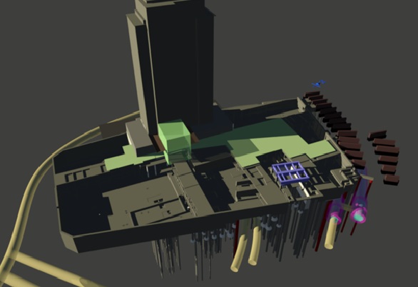
3D Modelling has been used to assess how much the raking piles were intruding into the basement footprint.
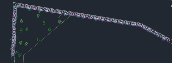
As can be seen from the image the existing secant pile wall is supposed to be installed where the white circles are. The dark green circles indicate the location of the pile at a depth of 15m. This is based on examining how far they are out of tolerance at a depth of 5m and extrapolating. A number of piles are raking significantly into the basement. These piles will have to be broken out and reinstalled. The plan for this is to break the pile out in sections and pour a concrete column to replace it. Analysis is ongoing to establish the effect of removing a pile from the wall. It will more than likely be limited to the removal of one pile at a time otherwise there is a risk of the whole wall failing.
It can also be seen that a number of piles are raking away from the basement. This will result in large gaps in the wall which will allow water ingress into the basement. In this case a relatively simple formwork design has been designed in order to allow concrete to be poured into the gap. To limit the pressure on the form work I specified that the pile infill must be done in 3m high sections. This will also allow the contractors to do the infill sequentially as the excavation continues.
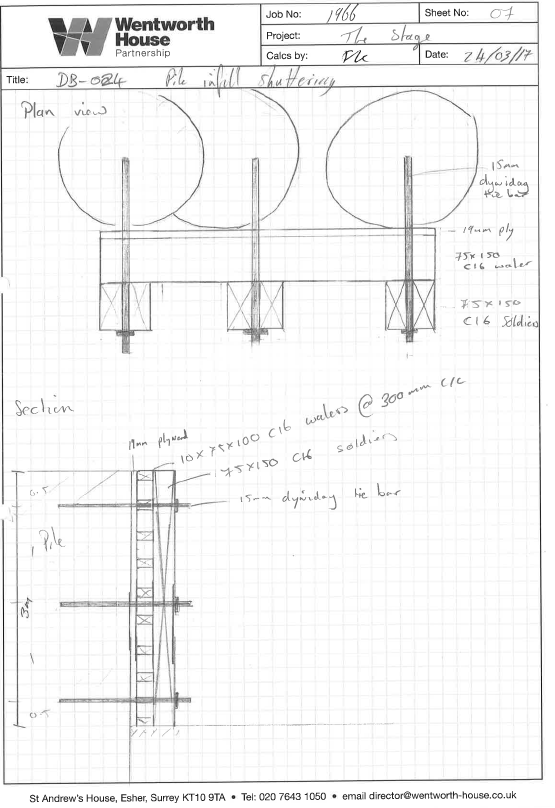
The above a sketch that I drew for the formwork design. This sketch was then converted into CAD by the CAD technicians so that I wasn’t giving the contractors a Freddie age 5 drawing but actually something with a whiff of respectability.
A really big crane.
I thought this may interest a couple of the civils.
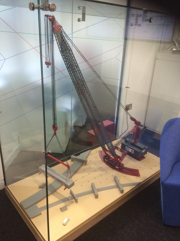
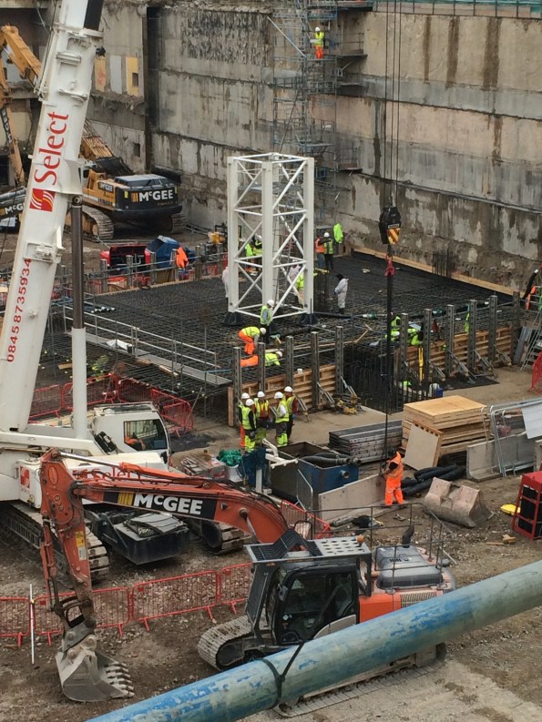
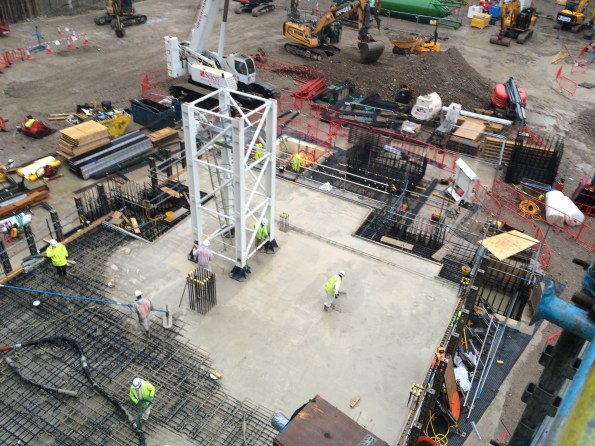
Keltbray have just erected the UKs tallest land based crane. The crane is to be used for the demolition of Market Place Station at Earls Court. The demolition requires the removal of all the station buildings (simple enough) and also all of the portal beams that span the underground lines running underneath the site (not so simple). There are 61 portal beams in total with weights varying between 200 tons and 1400 tons. The original plan was to break out each beam by cutting them into 20 ton sections and then lifting each section out. This would have taken up to two years to complete the beam removal and would have also resulted in numerous rail closures (in London’s current strike-riddled system this would have heaped even more misery onto commuters). The demolition plans were nearing approval when some bright spark decided to ‘go big early’ and suggested using a massive crane instead. The plan would be to make a cut at either end of a portal beam and then lift it out in one piece. This idea would shave years off the project program and was selected as the method for removing the portal beams.
As a result the crane has just been erected at Earls Court:

It stands at nearly 120m high and has a counter balance weight of 12000 tons.
Everyone at Keltbray is very excited about it.
This engineer built a 3D model. What he did next will SHOCK you…
Now that I have reeled you in with a click bait headline I will now proceed to chat about some fairly mundane Phase 3 stuff.
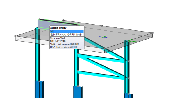
I have recently started Phase 3 with Wentworth House Partnership (Keltbrays’ Temporary Works department). On day one I was given the task of conducting a CAT 3 check on a facade retention system for a hotel in Burma. Essentially a large steel frame has been designed to hold up a wall and I need to check the design to ensure that it is safe and can be built (for the civils out there this is effectively like doing Ex STEEL but with trickier parts…..and yes I have already cursed whoever wrote the Eurocodes as they are as hard to follow as ever!).
To cut two weeks of steel design short I am just going to talk about one part of the process which is turning a complex model into a simple one in order to analyse it. In this instance I was trying to establish what load the piles supporting the facade retention system (and the facade) would be experiencing. The complex model is a 3D model that I built on a programme called Tekla Structural Designer (this is a lot like STAAD Pro but I think it is a bit more user friendly). I built the model by meticulously studying the engineer detail drawings and the associated CAD files so that I could turn a 2D drawing into a 3D model.

A screen shot of the Facade Retention System model (please note that this is just a section of a much larger frame)
I then added wind loading to the frame and was therefore able to analyse the frame within the model and get the vertical reactions at the supports due to the wind loading. I then created a separate model to analyse the effect of all the loading (wind loading, weight of facade, weight of Facade Retention System and self weight of the concrete slab that the facade and the retention system were sitting on) on the piles below.
a view of the 3D modle I used to analyse the effect of all loading on the piles
From this separate model I was able to use the programme to view the total reactions on the piles and therefore use this value to check is the piles were adequate.
A 3D model is a fairly complex model and I needed to verify that the results the model was showing me were accurate and could be trusted. Consequently I had to simplify the model so that I stood a chance of being able to analyse it by hand. I decided to model the problem as a beam with 3 supports (the supports being the piles). I then applied point loads for the weight of facade, weight of facade retention system and wind loading and applied UDLs for the self weight of the concrete slab. Using moment distribution I was able to find the reactions at each of the supports and was please to see that they were fairly similar to those that the 3D model was giving me.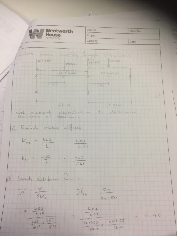
The problem ‘simplified’.
The lesson learned from all this is that what appears to be quite a complex problem can be simplified into a relatively simple problem that can be used to verify real world issues (assuming you can remember how to do a moment distribution…..it took me far longer then i’m proud of. Good job I kept my structures notes!). The basic principles taught on Phase 1 have paid dividends and I am still managing to maintain my thin veneer of competency.
Sustainable development on site
Fellow PETs, rather then clog up the Watsapp I thought I would bring a query here…
Whilst writing AER 3 I have noticed that I have still some way to go to get ‘Ability’ within ICE attribute 7 – Sustainable Development and I was wondering what methods other sites have. On site at Southbank Place there are a few schemes that they have used to try and tick the sustainability box; they have employed operatives from the surrounding area, use sustainably sourced aggregate for the concrete (according to London Concrete anyway!), used precast elements in the design and not worked past 1800 so that there is limited noise pollution. To me, there does not appear to be a massive emphasis on being sustainable; it is just a box to be ticked. I went to Laing O’Rourke’s in house lecture (delivered by the project leader on site) on how they are improving sustainability across the business. The project leader managed to cram the hour long presentation into 10 minutes and left me with the feeling that sustainability was viewed more as a hindrance than anything else.
Has anyone had similar experiences? What sustainable development initiatives have you had on your site?
Progress at Southbank Place
In an effort to convince everyone that I am in fact not working in a deep hole under the Stirling lines I have decided it is high time I blogged to give everyone an update on my project at Southbank Place with Expanded Ltd.
When I last blogged we had just poured the first segment on the basement raft slab. This incorporated a tower crane, drainage runs and sumps, earthing and lightning protection and a lot of concrete. Since then there have a further 27 pours for the basement raft slab using over 7000m3 of concrete and over 1000 tonnes of steel. The basement team (of which I am part of) are responsible for taking the buildings from level -3 to ground, after that the superstructure team take over. The raft slab is 1250mm deep whilst the floors above are 300mm suspended slabs. We have gone from the raft slab on level -3 all the way to ground level on 3 of the 7 buildings being constructed and are now stating the raft slab for the next building. Concurrently to all of this the slipform team have completed the cores of the buildings and are now waiting for the raft slab of the next building to be completed.
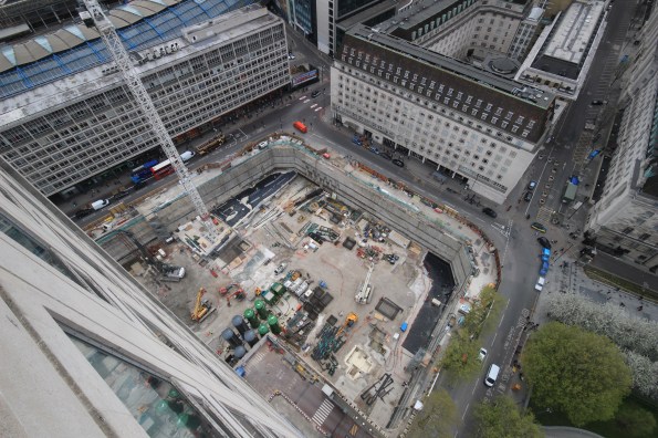
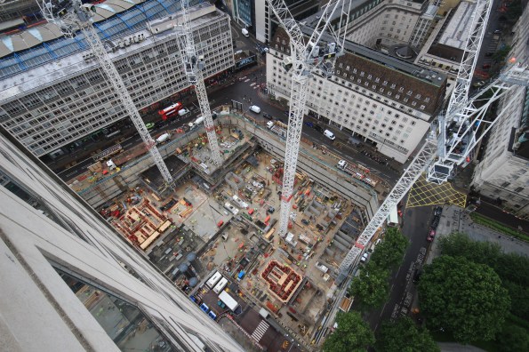
The site in May. One pour completed, a tower crane up and works continuing in other areas.
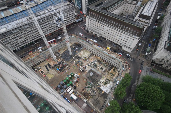
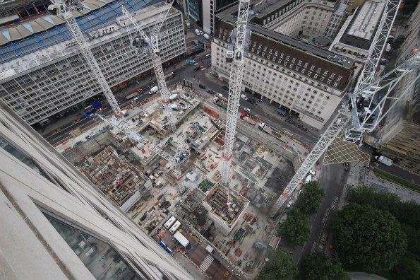
By June there have been another 6 raft slab pours and another tower crane erected
July: more cranes and concrete. You can see the slip form teams preparing the cores for ‘slipping’
August: Slips have stated and basement levels -2, -1 and ground are starting to be finished. -3 raft slab is complete.
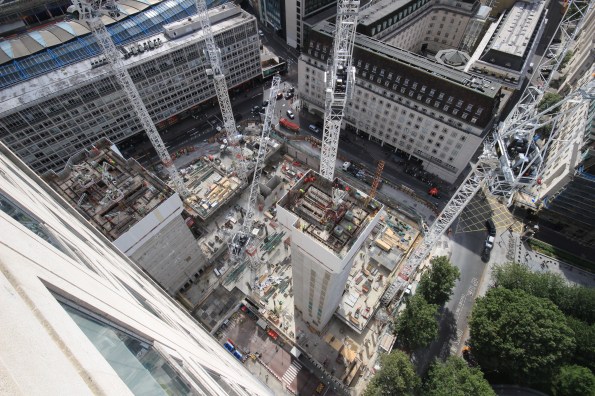
September: Ground level nearly complete and slips almost at full height.
Along the way there has been many trials and tribulations as the project has been pushed forward at a relentless pace. The construction manager has a plan on how the project will get built which, a lot of the time, differs largely from the project programme. As a result no one actually looks at the programme anymore, everyone just waits to hear what the construction manager wants to do one week to the next….it is his way or the highway. Even the senior project managers bow to his every command and go with whatever he says. I find this a very odd way of going about business but the project is going forward at a rapid rate so it obviously works. There has also been a high turnover of engineering staff on the job. Out of a team of 12 engineers there are only 4 (myself included) that are still on the job now. I personally think the high turnover is a product of the ‘unique’ management style but I may be wrong.
Other issues that have been encountered include ‘feeding the beast’. This is the process of making sure there are enough materials (rebar, waterproofing, drainage, etc) on site for the workforce so that there is no delays to the project. Whilst this seams incredibly simple it is surprising how often you will only get told when they run out of equipment….never when they are just running low. They are all aware that they just have to use the materials, not order it. I’m sure that everyone else has this issue and is equally frustrated by it.
During my time on site my role has moved from being the senior engineer on the -3 raft slab (now complete) to managing the handover package. This involves directing the ‘making good’ team and liaising with the client (Canary Wharf Contractors) in an attempt to handover sections of the basement to them so that further trades can start work. They are yet to take a single area due to a variety of minor defects ranging from small cracks in the slab to plywood being left behind a corner. I think that they are just trying to play hardball on the first set of handovers but if I keep promising them the world and laughing at their jokes I’m sure they will accept the areas eventually.
For any Phase 1’s reading this Southbank Place will still be in full swing when you go to placements in February. Whilst it is hectic and demanding there is a large amount of experience to be gained so if you have never been on a construction site before it could well be the place for you.
On a side note I interviewed for a Phase 3 attachment with Wentworth House Partnership. As part of the interview there was a structures paper…..needless to say it was a bit of a shock to the system. However the office is only 3 miles from my house so I’ll get over it! I will be starting there after I have conquered the slopes of Austria on Ex Racing Ice.
The drawings become a reality!
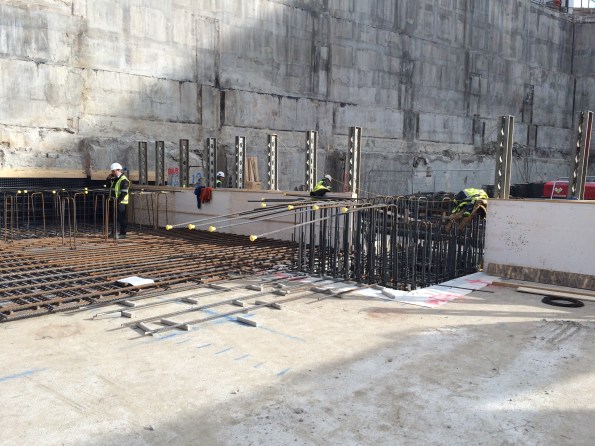
We are finally building! After weeks of delays waiting for the demolition contractors to handover the basement area and only have sketches of what will be built to look at, we finally got hold of area 1.1 (number 1 of 21 areas) where we will be constructing a 1.25m raft slab. This area in particular has a lot going on; temporary and permanent drainage, a tower crane, two sumps and several columns.
The initial task once handover hand been completed was to waterproof the area of the pour. This involved laying ‘egg crate’ (drainage membrane) on the ground where it will act to diffuse pore pressure and stop any water that enters underneath the slab from building up enough head to affect the slab. The waterproof system that is being used is SIKA. From what i can see this system seems to be a licence to print money. SIKA will only provide their 15 year warranty after one of there representatives has inspected it, and will only sign it off if their products have been used.
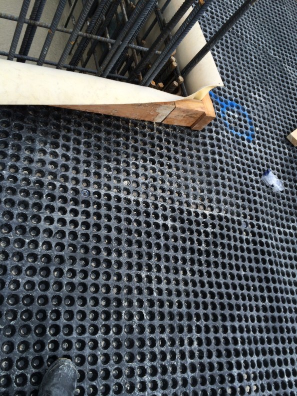 This ‘egg crate’ will be laid across the entire site.
Once the egg crate had been installed, a 50mm layer of blinding was placed on top before the steel fixers moved in. Unfortunately one of my duties at the moment is ordering and managing all rebar for the basement. After initially laughing off suggestions that this was one of the harder/stressful things for an engineer to manage ( I believe I said “how hard can it be?”) it has become the absolute bane of my life. After 6 deliveries there has been something wrong with almost every one; late, wrong or has bits missing. This would not be so bad if the site has stock rebar lying around, however the QS department will not allow such a thing and we are only allowed to have the exact bars that we need on site. This means that when a bundle of 50 bars is left in the yard in Wales and doesn’t make it to London it becomes a major issue. The construction manager does not want to hear the word ‘delay’ at any time!
When the correct rebar is on site the steel fixers throw it in very quickly. This pour alone had just over 35 tonnes of rebar.
Bottom mat being installed alongside one of the sumps.
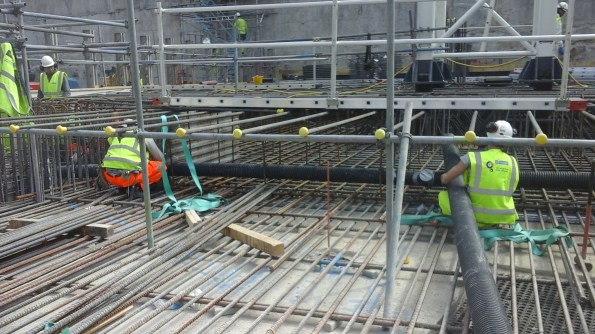
Further work on top and bottom mat. Drainage being installed on the foreground, crane base can be seen in the background.
The crane base was particularly tricky to install. Four concrete plinths had to be cast into the bottom mat and the base lifted into position on top of them. There is a 0mm tolerance between the four legs. Therefore this required a lengthy exercise of adding/removing steel shims from underneath the legs and tightening the leveling screws. This is much easier said than done and it took a few hours before there was a 0mm difference between all four legs.
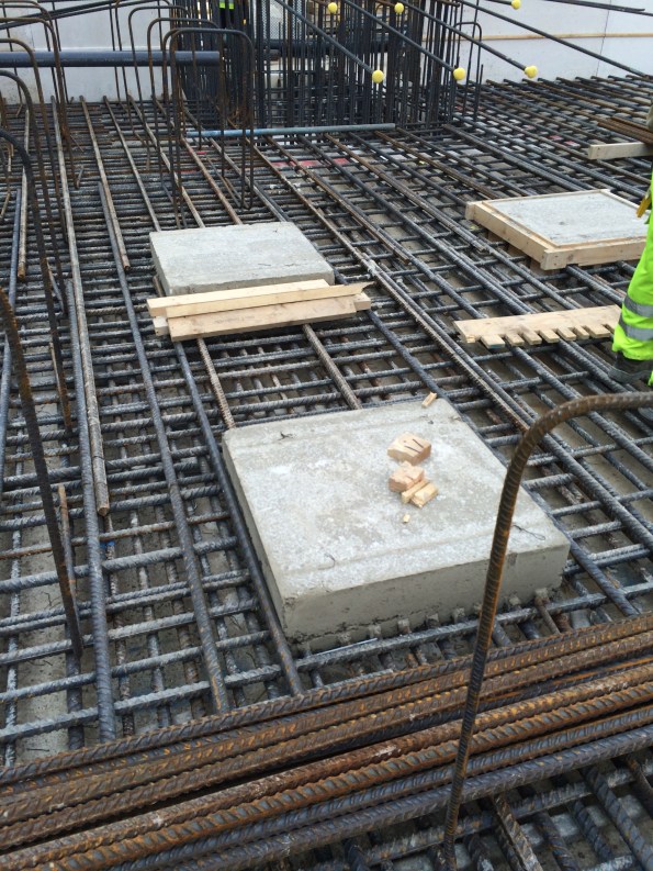
Plinths ready for a crane.
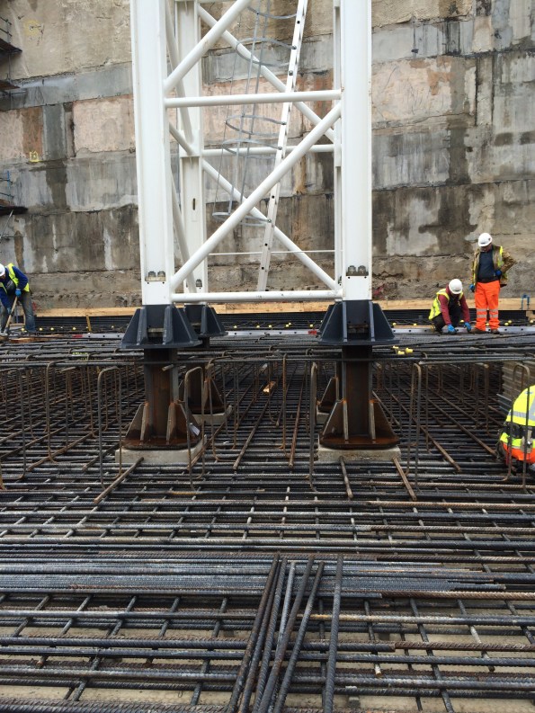
crane base in position.
After 6 days of of steel fixing, carpentry, welding and lots of other things the area was ready for concrete. 320m³ was poured in one very hectic day, it took around 12 hours to get it finished and this is not the biggest pour on this project by a long shot. At peak periods we will be pouring around 3 slabs a week.
The area ready for some concrete
About 10hrs into the pour.

the pour would need to be power-floated. Note the large puddles forming due to the torrential rain that came down all day. The gaps between the crane base and the concrete will be grouted at a later date.
A busy few weeks on site and only set to get busier. The main issues encountered so far have been:
- Stores – Expanded operate by using a ‘just in time’delivery philosophy. The materials they need will turn up at the right time in the right place, therefore removing the need for large stock piles of equipment on site. In theory this is a good way to go about it, however, in practice there are many times when the right stores do not turn up or are sent to the wrong place thus creating a threat to the project timeline.
- Logistics – the site is very restricted and has a complex logistics system that goes with it. The gatesmen will turn away a vehicle if it is not on their list so all deliveries have to be booked in a week in advance. Again, this does not work well in practice as there are always last minute deliveries and changes to the schedules. I have had to sweet talk them on more then one occasion to get them to let a last minute delivery in.
- Overzealous construction manager – not really that much of an issue, more a minor bugbear. The is a very specific schedule with pours taking place simultaneously and lots of moving parts. One of those moving parts is the construction manager. He has been a coiled spring waiting to start work and now that we have it is hard to reign him in. Everything must be done NOW, regardless of whether there is the stores or manpower with which to do so. He has been nicknamed the Tasmanian Devil as he sweeps through the area and causes havoc and confusion but somehow manages to get the job done.
On a separate note, today I brought another cat. I am one step closer to becoming a crazy cat person.
The calm before the storm…
On the 29th February I started work for Expanded Civil Engineering on the redevelopment of the Shell Centre. Expanded are a business group of Laing O’Rourke so all of the employees in the site office are Laing O’Rourke employees but are wearing the Expanded badge.
The project is a redevelopment of an existing site which was completed in 1962. The 1962 complex consisted of a high rise tower with a connecting 12 storey reinforced concrete low rise “horse shoe” shaped wing building. The existing structure is a concrete framed building above a podium with two levels of basement below. The site itself is adjacent to the major transport hub of London Waterloo. It is bounded by York Road to the east, Chicheley Street to the south, Jubilee Gardens to the west and the railway viaduct to the north. Running rail tunnels such as Bakerloo and Northern lines run beneath the site.
The redevelopment master plan has a mixture of commercial and residential buildings. The scheme retains the existing Shell Centre tower and site wide basement raft slab and walls with demolitions above and below ground, and with new construction comprising 2 commercial and 6 residential buildings with a two-storey basement in the north and a three-storey basement in the south of the site. It is worth noting that the residential buildings will have no social housing. The government requires up to a third of all new residential buildings to be affordable housing. However the owners have got round this by investing in a local school. It would appear there is far too much money to be made in this central location to waste it on social housing!
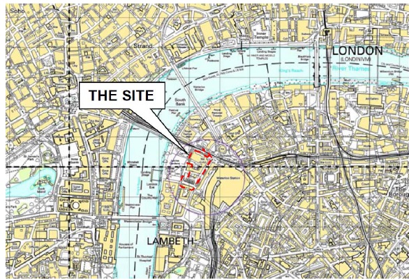
Site location
The proposed development will broadly comprise:
- Demolition of the existing site building, with the exception of the Shell Centre Tower
- Extension of the existing basement in the north east corner of the site and around the London Underground Ltd (LUL) ticket office
- Reconfiguration of the LUL ticket hall
- Construction of a new site-wide two-storey basement structure within the confines of the existing basement
- Construction of eight new mixed commercial / retail and residential buildings
Currently separate contractors, McGee, are completing the demolition of the existing buildings. They will demolish all the buildings down to their structural slab level. The site will therefore have multiple starting levels as shown below.
What the site should look like after the demolition works have been completed
The demolition works will be ongoing for a number of months and leads to a very congested site. However, Expanded (and more importantly the client) are keen to get working the moment there is enough space so construction will start in the southern end and follow the demolition works sequentially through the site.
 An example of how congested the site can be; the Expanded piling rig is in the background
There is also a growing concern with the construction plan changing last minute. McGee have proceeded with the demolition quicker than expected and the client therefore wants to accelerate the raft slab construction process. This would involve changing the whole sequence of slab pours and presents additional logistical challenges. The project engineer has so far not changed any plans as he is sure McGee will slow down soon.
An interesting factor has also occurred with a dispute between Expanded and McGee. It has been discovered that the guide wall for a secant pile wall has not been put in the right place by McGee (this has many in the Expanded office scratching their head as no one is sure as to why McGee, the demolition contractor, was tasked with casting a guide wall for Expanded). There is an ongoing dispute as to who is going to pay for it as the site was handed over, although no as-built survey was complete prior to hand over which is why no one has picked this up until just before the pile rig started piling. The dispute is ongoing…
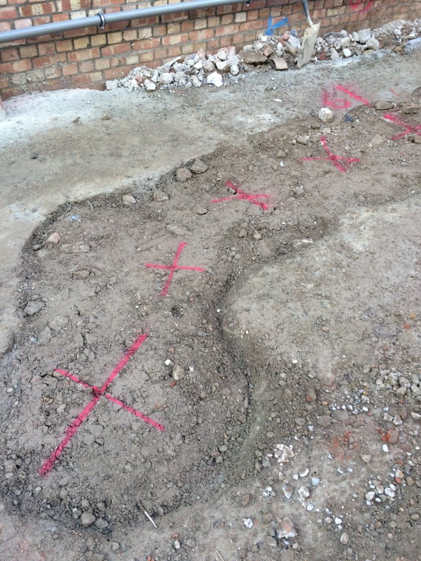
Red crosses show where the center of the piles should be compared to the guide wall
Currently we are in ‘the calm before the storm’; we will not be starting work on the basement raft slab until later this month and there is only minor ground works ongoing for the time being. In the mean time there is a lot of planning and work going on as most of the method statements for the works are yet to be written. This is quite frustrating for me as I find myself (much like phase 1!) writing method statements for processes I have only ever seen on paper. As a result I have to ask for guidance every half an hour! However I will be getting plenty of time on site in about 2 weeks for the foreseeable future.
In other news if anyone on the patch in Kingston fancies a game of squash, Jonny and I play at 1930 on a Wednesday night.
