Archive
P for Plenty
This post is probably about a two months out of date, but I wanted to blog about it because I’m genuinely interested to see if anyone else has seen a similar experience on attachment.
I have seen the ‘Go Big or Go Home’ philosophy applied numerous times in my professional career, both within and outside the military. Arguably, generous safety factors in military PAMs are just one contributing factor to the P for Plenty rule.
During my final few months of site attachment, I experienced the same phenomenon in the design of one particular intake louvre, at Mascot train station. This sparked my interest in the fundamental design of the louvre and the engineering principles that had been applied to reach the size specified in the design.
Safety
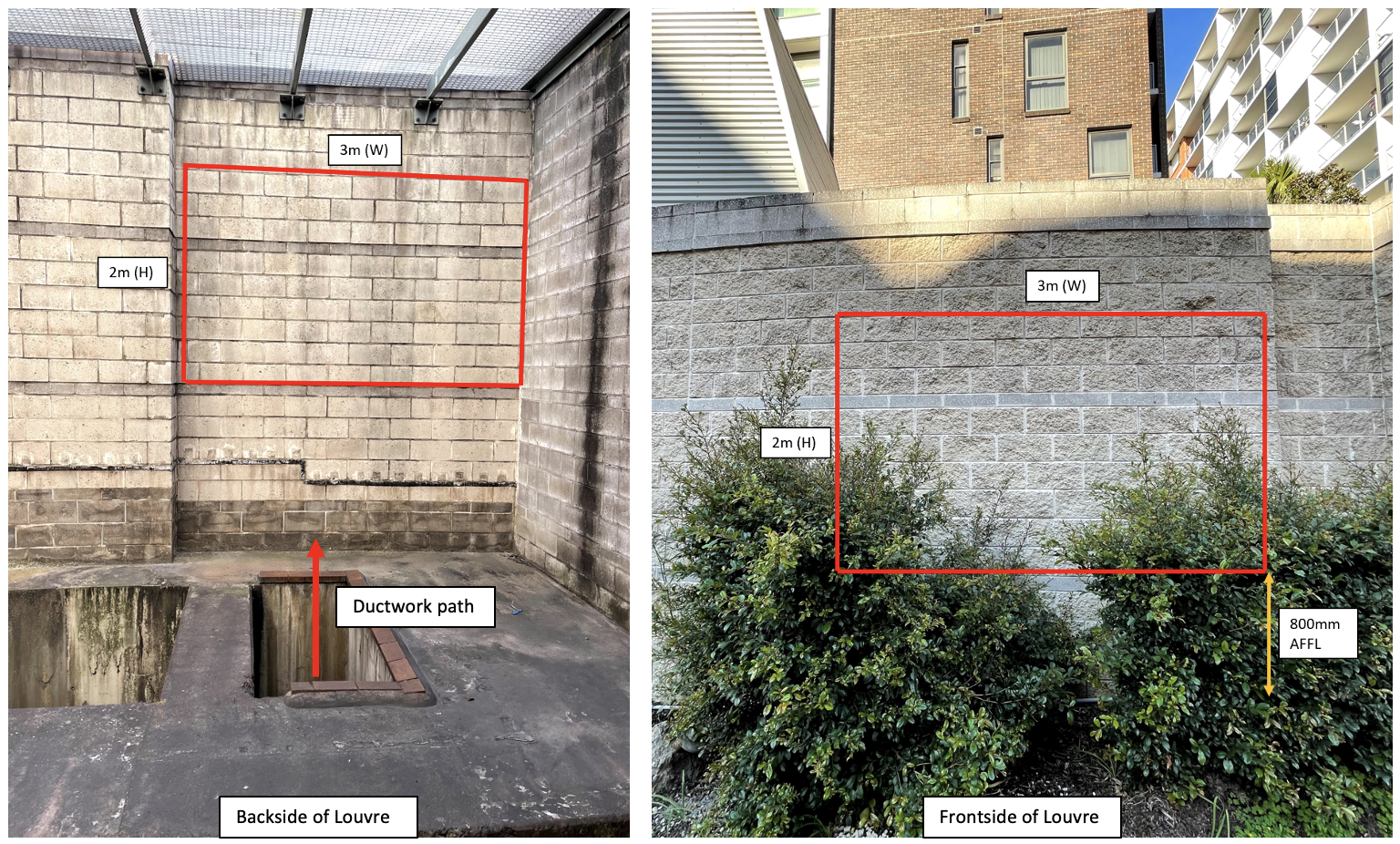
The main reason I took a strong interest in the design of louvre was related to constructability and safety concerns. The design positioned the louvre in a blockwork wall in the train tunnel exhaust structure of Mascot train station. Ductwork fixed to the back of the louvre would then convey fresh air through the exhaust room below and into the cable tunnel adjacent through the station diaphragm wall. Fig 1. below shows the exhaust room in more detail. I’m sure you can appreciate the access required (scaffold towers on the yellow and green areas) to install not only the ductwork at ceiling level, but also the louvre about 10m above the floor level.
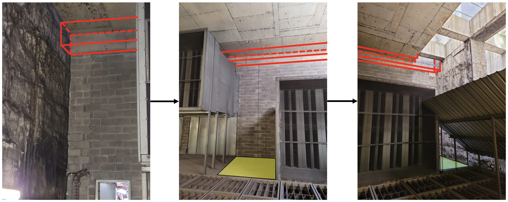
Risks fall into two timeframes when constructing the louvre:
- The scaffolders constructing working platforms in the tunnel exhaust plenum for the mechanical and louvre subcontractor. The motorised floor dampers (automatically controlled) in Fig 1 lead straight down onto live rail tracks.
- The subcontractor constructing the louvre in the blockwork wall. The gaps between the concrete beams (shown in Fig 2) drop down >10m to the exhaust room shown in Fig 1.
Any reduction in the louvre area (original design shown in figure below) would not only reduce the risk exposure time for the workforce, but also assist the civil team in constructing the lintel above the louvre. My immediate question to those with civil/structural experience would be in the current markup below, the lintel would not have any blocks to rest on! Any solutions appreciated?
Design
I approached the designers and asked to see the calculations that produced a louvre area of 6m2 when the ductwork CSA is only 1.5m2. Basic fluid mechanics states that Q=AV and so I appreciate the louvre area (A) needs to be larger to reduce the face velocity (V) to achieve the same volumetric flow rate (Q) This lower face velocity at the louvre assists with water ingress, pressure drop, and public safety. However, a louvre 4x the size of the duct seems large!
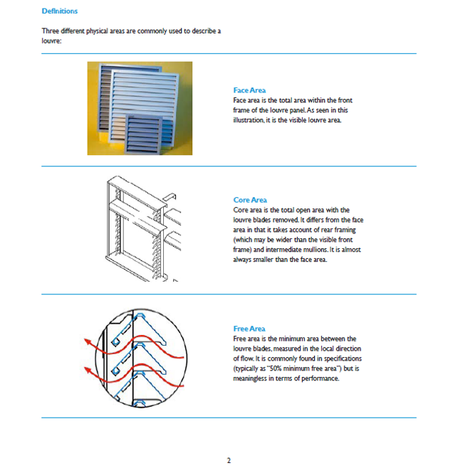
On further investigation, it appeared there was misuse of the louvre free area in calculation in addition to a generous safety factor and a design air face velocity of 1m/s. The free area is usually provided by the manufacturer and represents the minimum area between the louvre blades expressed as a % of the total louvre area. Numerous sources explain that the free area is meaningless in terms of performance and should only be used as guidance. More detail on the different louvre areas is described below.
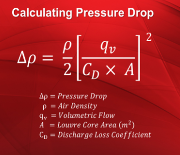
The two errors mentioned above led to a significant over sizing of the louvre. Running the numbers through a rearrangement of Equation 1 produced a louvre area of 4.5m2. After numerous discussions, the designers agreed to reduce the area of the louvre to 5m2, whilst still maintaining a suitable safety factor. This area reduction leads to a face velocity increase, however, the designers recommended two-stage louvre still maintained a 100% water ingress effectiveness at speeds up to 2.5m/s. In summary, the pressure drop and water ingress at the reduced louvre area was still suitable.
I’m intrigued to hear if anyone else has experienced over design, either through miscalculation or large safety factors on Phase 2 and 3? If so, what were the implications in terms of constructability, cost etc?
Time vs Quality – 5 mins Read
Throughout construction projects we are continually reminded of the time, cost, quality conundrum. Other than relatively small military construction tasks, rarely have I experienced this compromise so evidently as in the example below. Conceptually, it makes complete sense that you cannot achieve all 3 at the same time; designers, engineers, construction managers must appropriately select the driving force and stick to that philosophy throughout all stages of project management.
During a recent weekend rail possession on the T8 Airport Line in Sydney I found it extremely obvious to identify the critical driving factor – TIME! During a rail possession, the train line completely shuts down and contractors across all industries are then able to safely access the track, whilst the public are ushered onto replacement buses at a cost of approx AUD $10 million for the weekend. Among a large number of tasks to be completed by various contractors, I was working as a site engineer for small core holing and cable pulling task in Green Square Station.
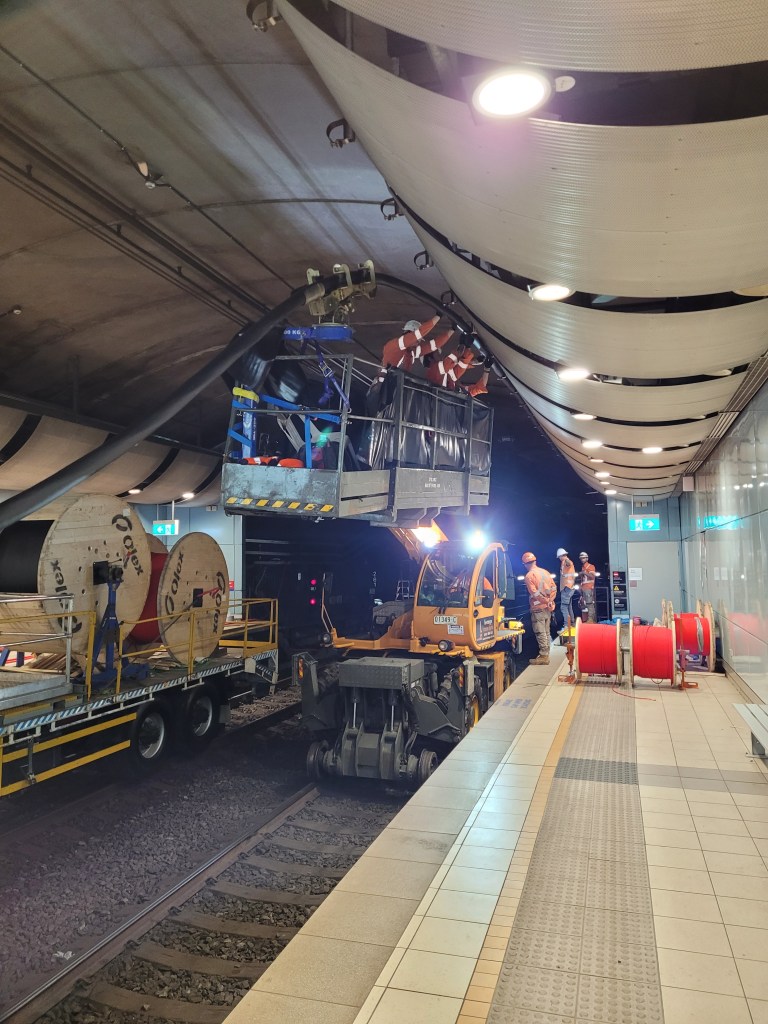
It was made clear to all staff and sub-contractors involved in the task, that the track and all stations needed to be handed back to Transport for New South Wales (TfNSW) at 02:00 on the Monday morning, ready for the Monday morning commuters. I would imagine the cost of not achieving this deadline was too large to comprehend and would cause a large headache for senior management!
Without compromising workplace health and safety, the clear goal was to complete the task by the deadline, at the expense of quality. On a number of occasions this was obvious to see….
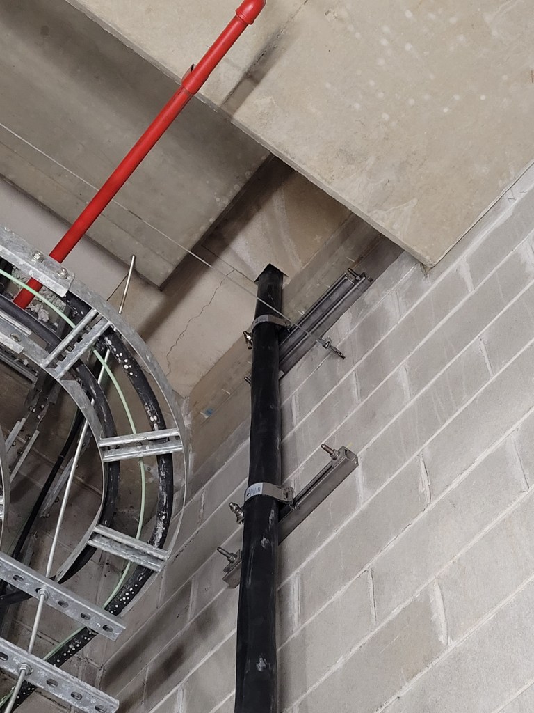
The brackets were pre-positioned before the cable pull and therefore the 11kV cable could not be clipped into a few brackets along it’s length, in time – a clear example of a drop in quality/workmanship to achieve the deadline. Don’t panic, the brackets could be moved at a later date during normal station operation, as all the brackets were back-of-house.
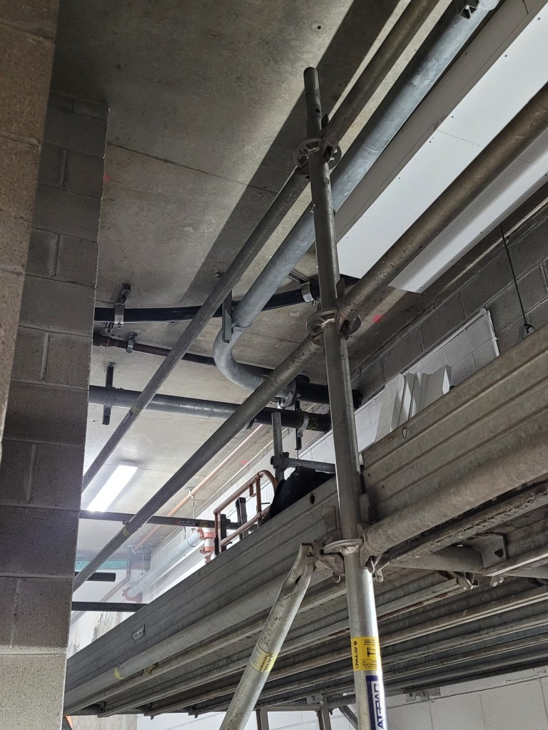
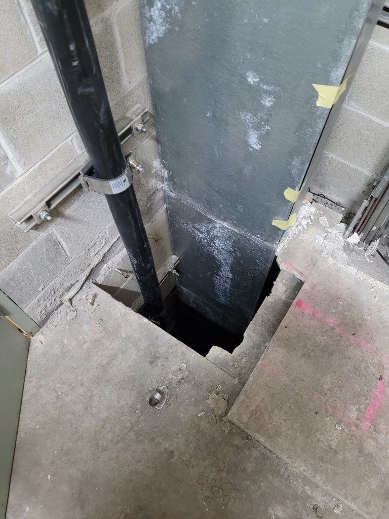
The 11kV cable weighs approx 15 kg/m and is relatively stiff which means it is a difficult cable to work with, especially when trying to bend the cable through various rooms and between multiple floors of the station. As shown in the images above, the result is that the cable pulling contractor scuff/mark the cable sheath as they work, in order to position it in accordance with the design. If required, cable jackets can be installed at a later date to repair any non conforming lengths of the cable. Just another example of a drop in quality to meet the deadline!
