Archive
I did that!
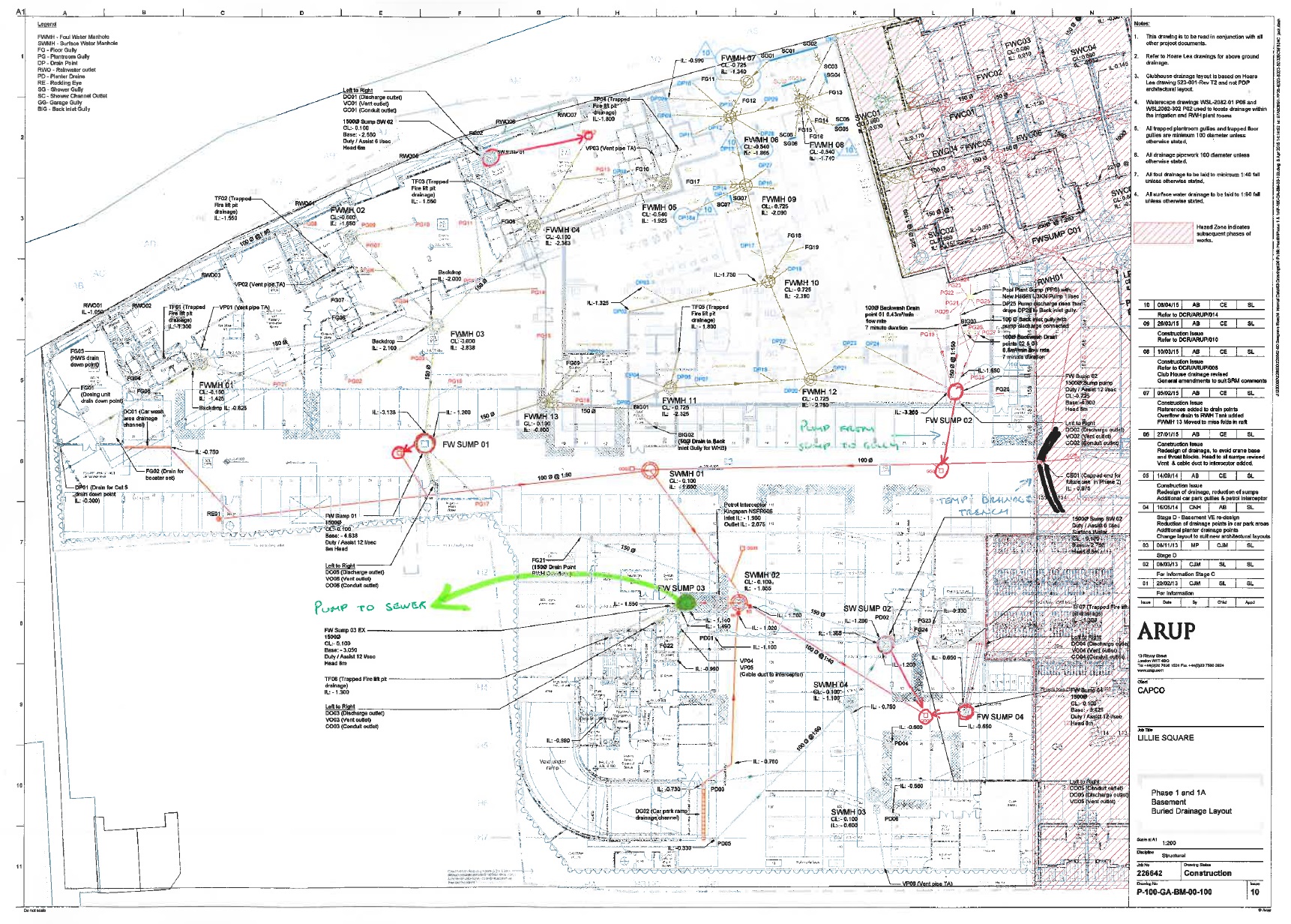
A074754 – 229 – 300 – Drainage Layout
…Unless it doesn’t work in which case someone else did it!
Today I received a pdf of the drainage design I did back from the drafty in Nottingham who drew it for me (see link above).
The site is an old National Grid gas storage site. A large part of it was sold off to Barrett homes who then built houses on it. In doing so they destroyed the drainage outlet and so now the site floods. A lot. So much so that the water is spilling over a small retaining wall at the north of the site and into a timber yard. The timber yard then floods and they claim against National Grid for the damage to their stock. National Grid have been saying to them for ages (the houses were build nearly 10 years ago) that they would do something about it and are only getting around to it now because they want to demolish the northern gas storage tank and the ground it too wet and soft to get the plant across.
To the west of the site and atop a retaining wall is another development. The drainage behind the retaining wall discharges onto the National Grid site and is causing the majority of the flooding. A manhole was once constructed there but never connected to anything. We’ve devised a ground drain to deal with the surface water while also lowering the ground water. This feeds into a new underground drainage system which then discharges into the river the far side of the road in the east.
The drainage design was pretty straight forward. I designed a similar temporary drainage solution during Phase 2 when the basement flooded (there is a blog about that one too). For this one all the leg work had been done for me, a drainage specialist in another office had run simulations and done other clever computer things and advised on a 150mm dia pipe running at a minimum fall of 150mm.
So all I had to do was draw some straight lines on a site diagram and specify the manhole types, invert levels and a few other bits and pieces that i’s learnt when doing it on site. Doing it on site previously actually gave me a huge advantage, I knew to specify a rocker pipe connection, a geotextile membrane and rocker pipe connections. All that stuff which is easily overlooked but important to making it work and not looking like a knob.
National Grid want to sell this bit of land as soon as the gas storage site is gone (probably to Barrett again) and so don’t want any on-going maintenance issues. Therefore the design must comply with the Anglian water adoptable sewers regs. So with a bit of reading I made sure the manholes, falls, diameters and all the other bits met the spec.
Now comes the hard part… In order to discharge into the river I need two things:
- Consent from the Environment agency to discharge into the river – this is actually easier than you’d think. We tested the water so we know it’s clean enough, so all we do is show them how we’ll be working safely next to the river and how we won’t constrict the flow. They then give us consent.
- Section 50 consent to dig up the road from the highways agency. This is more difficult. I’ve submitted our design Colchester tomorrow to meet with some bloke to take about crossing the road. Apparently they can only talk to me on site, they wouldn’t even tell me what depth they wanted it under the road in order to miss other services until I’ve met the bloke. Not sure what all the cloak and dagger stuff is about but it’s a day out of the office I suppose! The really kicker is that before they’ll give you consent you have to give them a cheque for however much they think it’ll cost to reinstate the road in case you dig a massive hole then leave it (or go bust).They also charge you for maintenance of whatever service you’re instating despite the fact that they also ask you to prove it will be adopted by the relevant undertaker.
I’m also told the bloke in question is mega boring, I’ll let you know how it goes…
Making Neil proud – again
No, I don’t mean I have just bought a shocking pink brad-esque jumper, I am in fact currently wading my way through NA to BS EN 1991-2:2003 in an attempt to calculate the load on a concrete slab that crosses a high pressure gas main to protect it from quarry vehicles.
It’s like calculation bridge loading, only on crack, and redbull, when you’re already as hyper as that bloke who taught us about drawings…
It you’re dealing with “abnormal” vehicle loading, eg. vehicles that aren’t allowed to drive on a road, you have to consider Load Case 3 as described in the EC. Due to the size of the vehicles I am dealing with the NA says I must use SV100 vehicle loading (see below).
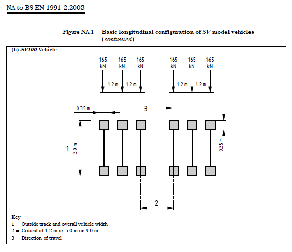
My question is, will this always be the most onerous case, in which case do I bother with LC1 or 2 or can I just do LC3 and call it a fish?
Answers on a postcard please…
Welcome to Phase 3
So after a nice period of leave (Iceland is a great holiday destination!) I am now in a design office.
I’ve been given two projects to get me started: designing a crossing point for quarry vehicles to get over a high pressure gas pipeline, and designing a drainage solution to a flooded National Grid site. Additionally I’m also getting pulled into a job designing a new facility for the Somalian SF next to Mogadishu airport, not too dissimilar to one I did for our SF in Lash just before it shut. So plenty to get stuck into.
Both of these jobs were sold to me as “nice simple ones to get started with”. Which it turns out is not true for either. The drainage job requires applying for a Section 50 licence to dig up a road and a discharge consent from the environment agency. The design itself is pretty straight forward but the hoops you need to just through are not.
The pipeline crossings job is more of a design headache as what I was told was gravel is in fact clay. Despite three different surveys being conducted, at no point did anyone do an SPT, or lab testing and so no Geo properties, ground water data or test results are available. So the first step is to get a “proper” site investigation done.
Additionally the company I am attached to (WYG – a fairly holistic medium sixed engineering consultancy) do the obvious structural, civil, mechanical and electrical design work, but they also do planning, transport, force protection, international development and aid work to name a few. So the plan seems to be for me to do about four months in the Civils/Structural design dept. (overuse of the work dept. – there are three of us in the London office) then a month in any three other depts. of my choice. I’m thinking International development, Project Management and Adjudication, but I’d be happy to get suggestions!
Note for Phase 1s
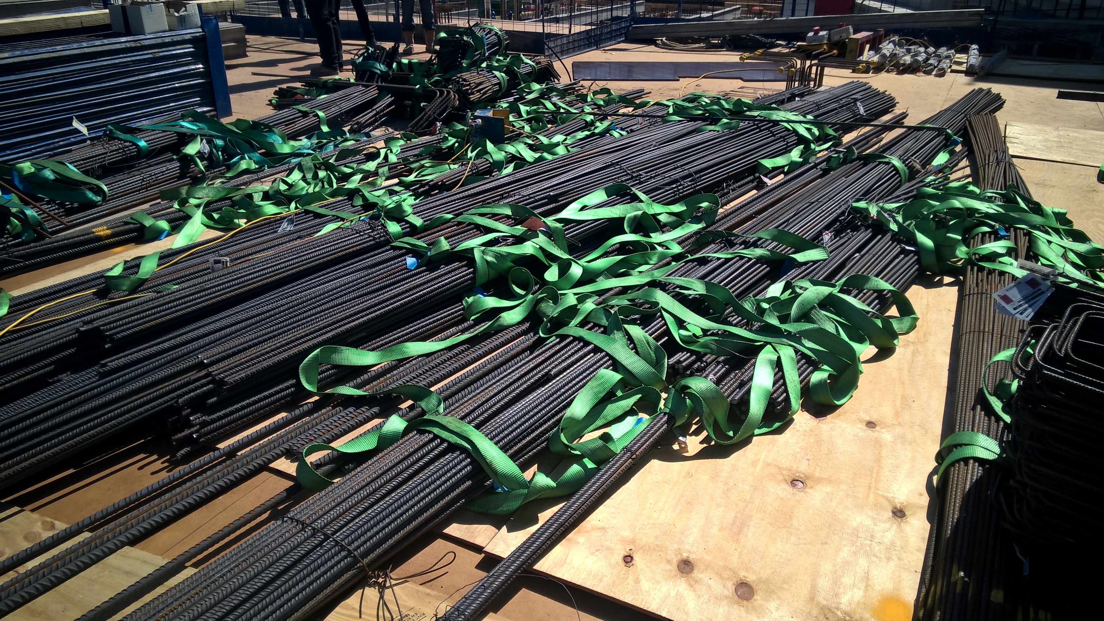
As you’ll know from visiting my site yesterday I have just one week left on site. Damo and Olly a little more, Dan and Daz a little more again. So if you want examples of things we’ve seen to put what you’re learning into real life context, photos of stuff we’re doing, or even just to ask about how we find our attachment locations, now is the time to ask. I am very happy to provide photos and answers and I’m sure the other lads are too. But get in fast as time is short!
Here is a picture of the steel as it gets delivered as a starter (requested by Richard):
How it should be done
To follow on from Daz’s excellent piece on tendering (if you haven’t read that, read it first), I thought I’d throw in my recent experience of procurement…
The architect, PDP, have design responsibility for the waterproofing, including the additional waterproofing measures required for the Grade 3 basement areas. PDP should provide a waterproofing intent that is then given to the geotechnical designers to analyse. Arup, the geotechnical designer, should furnish PDP with values that are used to define the performance requirement of the waterproofing measures. These figures should be applied by the architect to a catalogue of products and define a product. The supplier of that product are then responsible for the detailing of that product, the supply and installation.
None of that happened.
Instead PDP drew a waterproofing intent and went direct to the supplier approved by the client, Grace, to design the cavity drainage system. Grace (not Newton, sorry Henry) said they couldn’t do it. They could specify the product and do the detailing but they couldn’t do the pumps. Hoare Lea, the M+E designer, should have then been approached to do the pump design. Instead PDP went to a different supplier, one not approved by the client, Newton, and asked them to design it all. Which they did. At this point it is worth noting that PDP did not pay Newton for this design.
Sir Robert McAlpine (SRM) are now stuck with a design that is not approved by the client. The sub-contract for the supply and installation of the waterproofing does not include a cost for design. So that cost (and there must be one) must be included within the rates in the installation subcontract since no one does anything for free. In order to maintain the programme, the waterproofing has now been installed, so we’re far too far down the road to go back and do it properly so what can we do?
It looks like we’re going to have to either suck it up and accept that we’re effectively paying for the design twice (once to PDP and once to Newton), or we have to break down the sub-contractor’s quote and remove the element of design and contra-charge that to the architect.
This dilemma is currently sat with the package QS. Who has been saying for 3 weeks that he will do something about it, but hasn’t. This morning he handed in his notice so I somehow doubt this still sit’s in the Urgent and Important box on his list of things to do!
More to follow me thinks…
Health and Safety – go nuts!
In the last few weeks we’ve had a few incidents where stuff has fallen from height. The list of “stuff” includes a helmet, a 7 foot scaffold tube (which it a bloke’s arm), a screw jack, a sheet of plywood, reinforcement spacers, a length of rope, a section of edge protection barrier and a bolt. The length of rope was actually thrown off the side of the 6th floor intentionally!
It could be worse, on McAlpine sites across London so far this year even more stuff has fallen including: a scaffold board, a drill bit, a washer, a mobile phone, a metal plate, a brick, a lifting strop, 225mm concrete core, scaffold spanner, sheet of insulation, a pallet truck (how?!) … the list goes on. 95 objects in total. And that doesn’t include the bloke who fell off a scaffold!
In an attempt to curb this we got everyone together and gave them a little presentation about how bad it is when stuff falls from height. The presentation will be given to them again in their own language too, which will be a significant undertaking considering the number of languages spoken on this site.
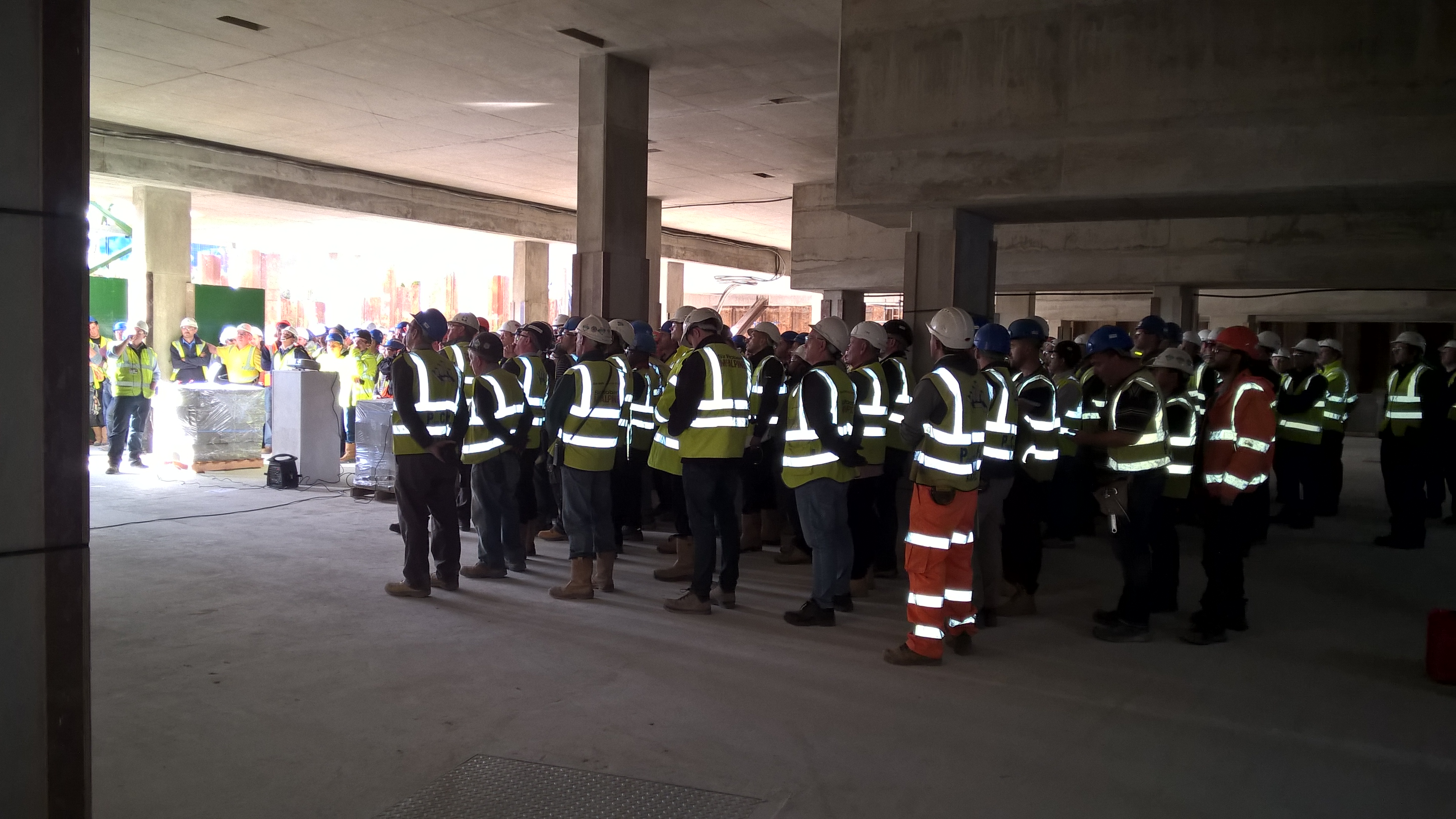
When walking away from the presentation I hear one scaffolder turn to another and say: “The thing is though mate, their not accounting for stupidity!” But he is wrong. These issues are not caused by stupidity. Well not all of them anyway. Some of it is an attitude problem. I’m sure we’ve all been to places where the value applied to life is less than it is here. Some of the people from that place have come here and now work in the construction industry and have brought that attitude with them. They’ve done it that way wherever they’ve come from and that’s what they’re used to. This is not to point a finger at migrants. Some of the old and bold from the construction industry are just as bad. Others do dangerous things because they are too lazy to do the right thing. I saw a bloke climb over a barrier because he couldn’t be bothered to walk around it. It’s not about nationality, or intellect, it’s about discipline! I’ve said this before and I’m sure I’ll say it again: at least in the Army all the idiots do as their told!
One problem that we have is that there is so much construction work in London that there is a serious shortage of competent skilled labour. We have forced our blockwork contractor to only use their own full time lads, not agency, in an attempt to ensure that the quality is maintained. Other sub-contractors have not made the same commitment and so staff turn-over is high as workers move around to whichever site is paying the most that week. This has a serious impact of things such as quality, but also safety as it takes time to indoctrinate the new workforce into the McAlpine way to doing it.
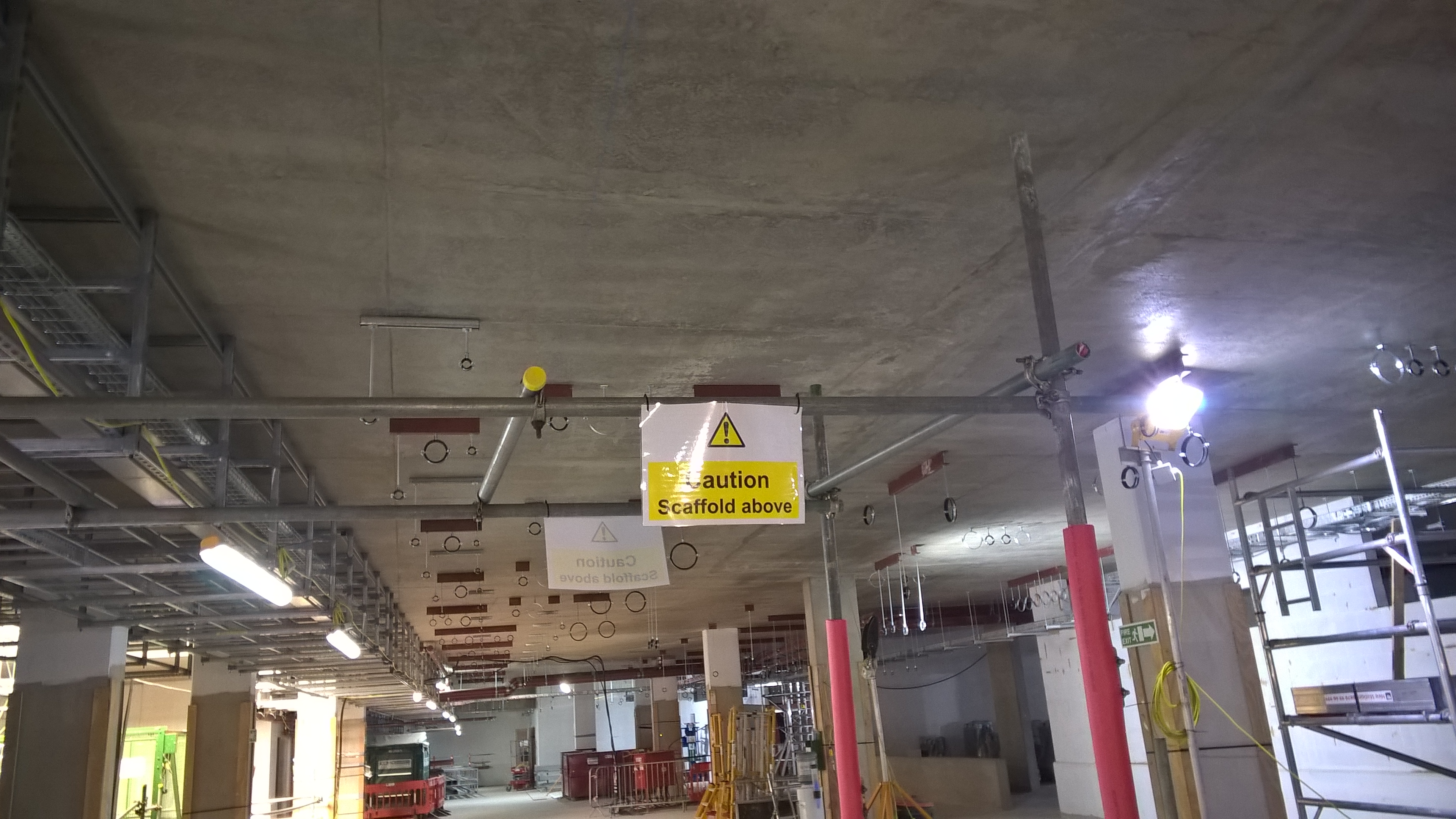
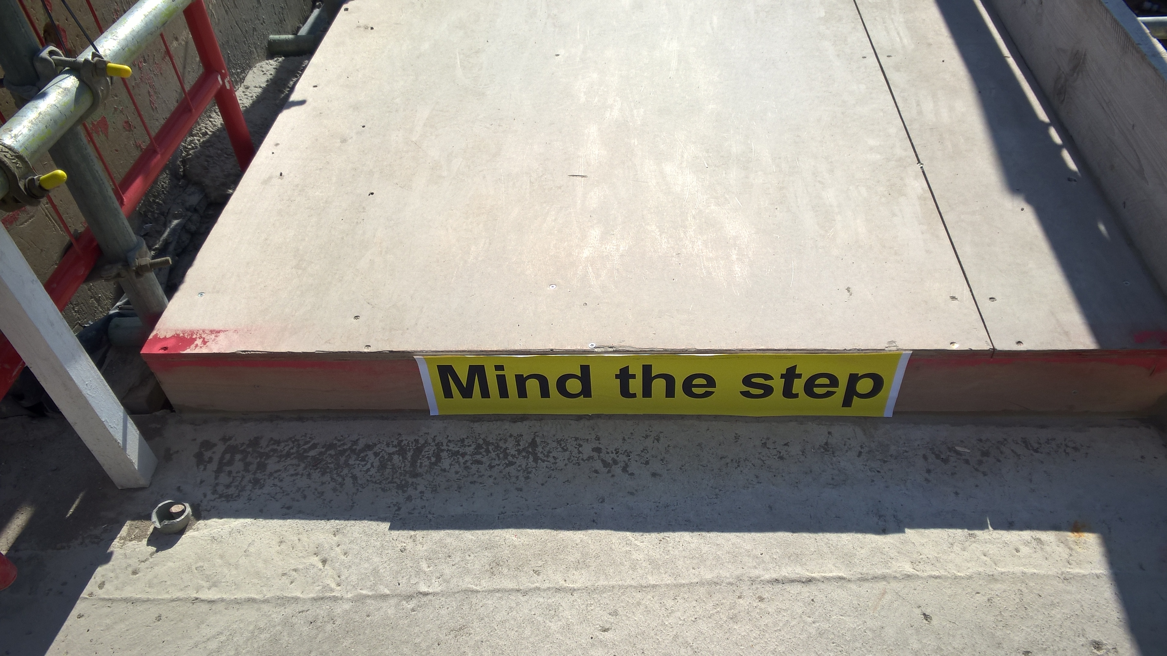
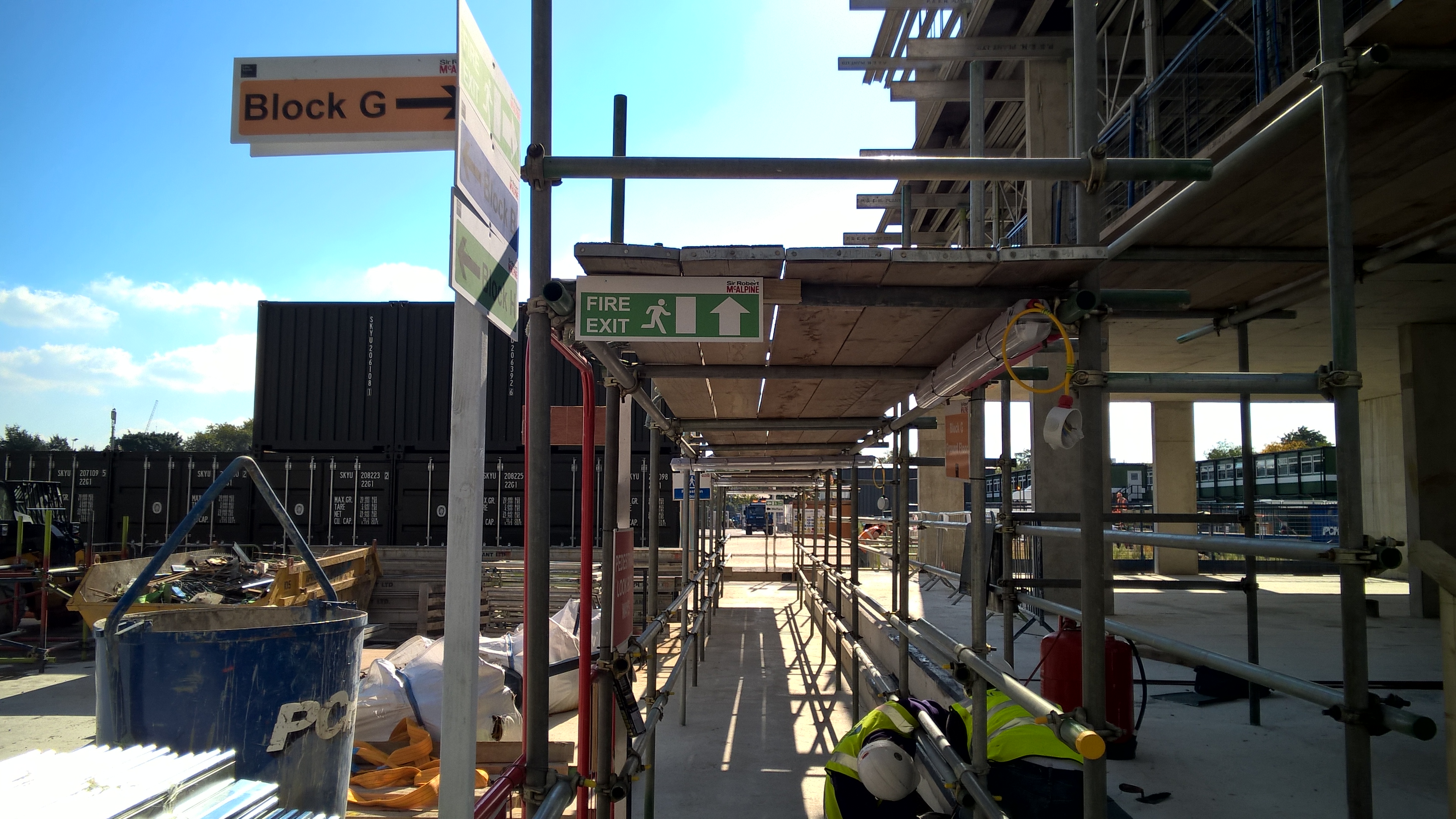
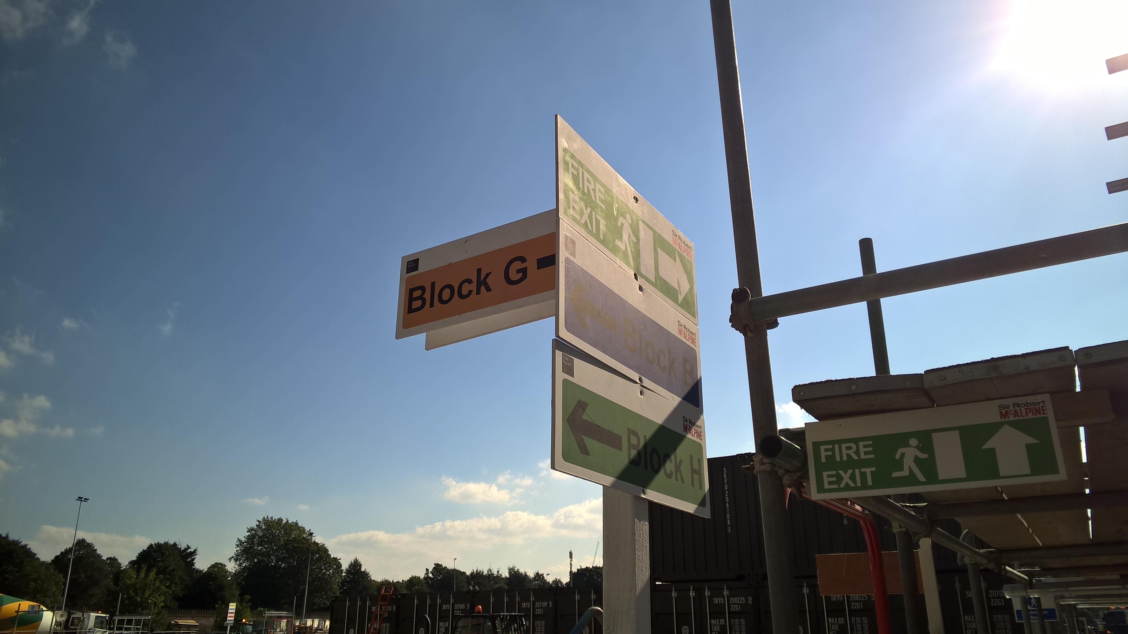
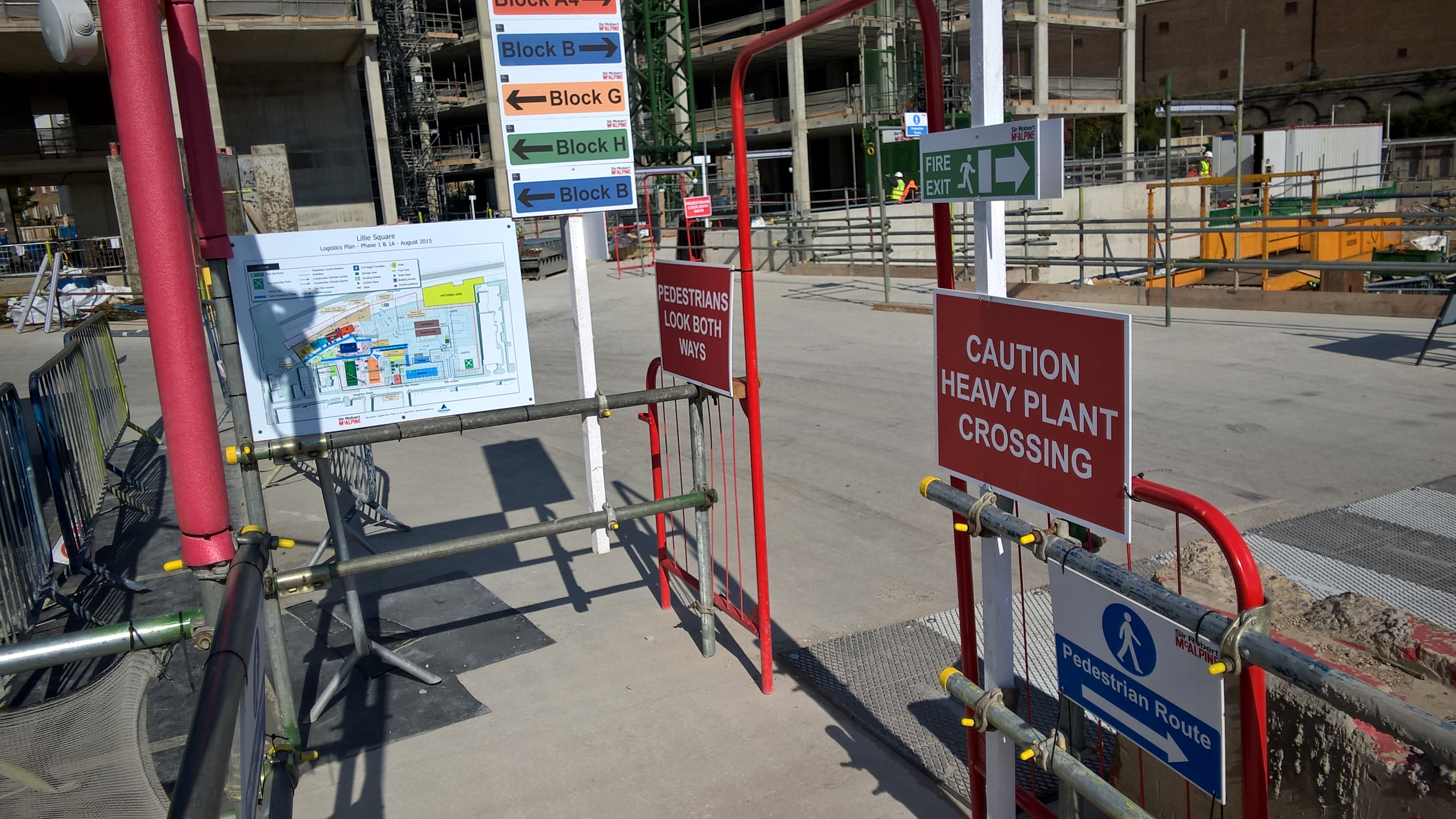
In others news: Our site now looks like a small child has got a sign making kit for his birthday and has just gone nuts!

Winding down
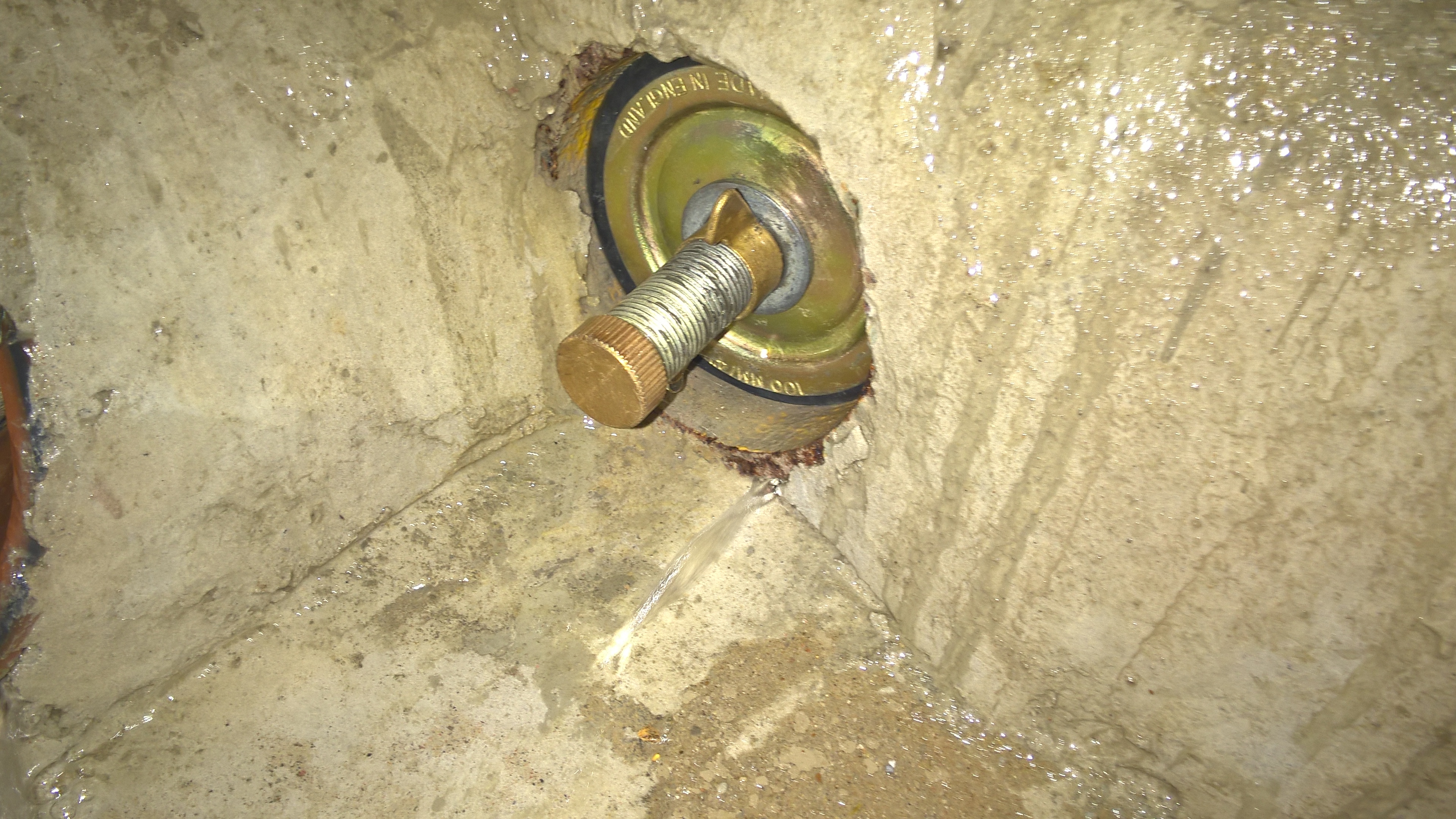
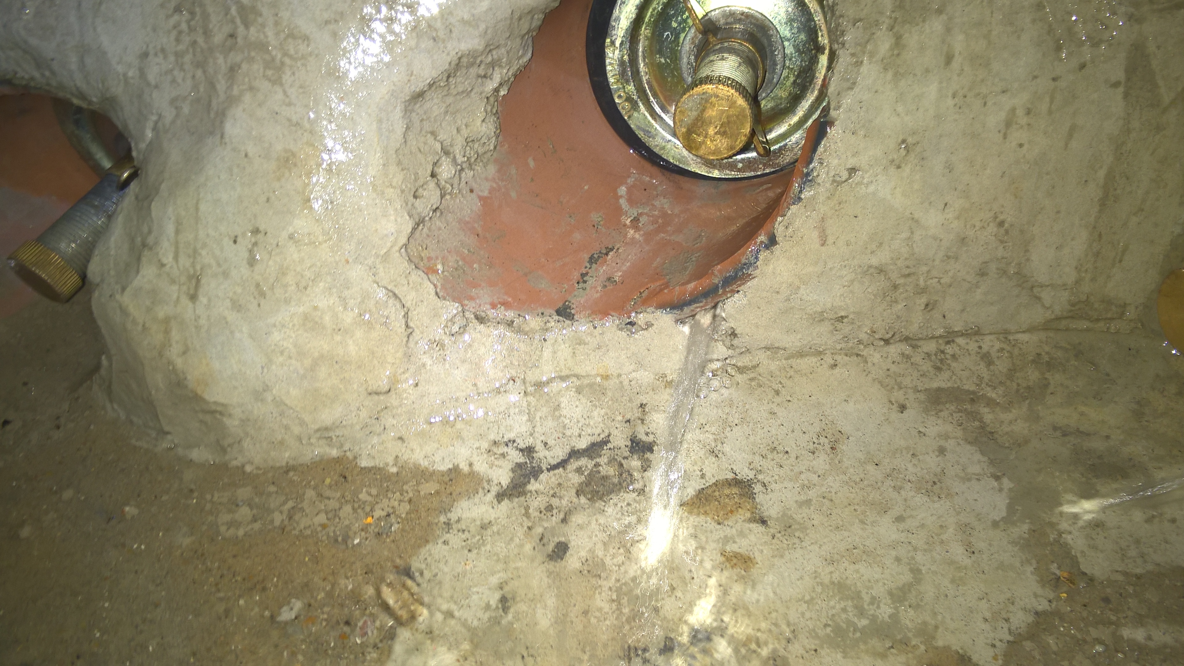
With a month to go left on site I’m conducting testing of drainage, finishing off the blockwork and still arguing over builderswork.
For the phase 1s: Manhole testing is something you will likely come across and dependant on the designer will either be completed in accordance with BS EN 1610 or (as in our case) a more stringent standard defined in the designer’s specification. In this case that is imposed by the designer due to the local authority’s own more stringent standards.
Effectively we fill the manhole with water, leave it for an hour to settle (for water to be absorbed into the concrete and air bubbles to escape), top it up to the original level then start the timer. After 30 minutes we measure the drop. If it’s less than 25mm it passes, more and it fails. Failure results in issuing an NCR (Non-Conformance Report) and tell in the sub-contractor to fix it. Four of ours have failed, mostly due to leaks where the pipes are fed through the pre-cast concrete rings that form the side of the manhole. The sub-contractor is planning on re-sealing the inside using a cement based sealant that is applied to the inside by a hand trowel.
As the blockwork nears completion the M&E (that’s “mechanical and electrical” in the civvy world not “mines and explosives”) contractor has decided this is great time to alter his builderswork drawings that show where they need holes to pass their services through.
The issue with moving the builderswork is not just that the hole needs to move, but the whole fabric of the wall. Where we have a double skin wall that includes all the insulation and waterproofing, and in some cases a windpost.
All the blockwork I look after is in the basement. So why does it need windposts I hear you say?! It’s because in the temporary state the building isn’t sealed and therefore wind can get in and apply a horizontal load to the face of the blockwork. In the double skin locations the windposts and located in the internal skins (so they are hidden by finishes) with a movement joint located in the same place on the outer skin.
For those of you who are overseas: You might well be in sunny Australia or gun mad America, but I went to the Rugby World Cup opening ceremony and England vs Fiji, so in my books – I win!


For those phase 1s who are reading this while on exercise Steel: Stop it! Watch Scotland vs Japan instead!
Small tweeks…
I’d like to echo Damian’s point when he said that it’s important to question the design. It’s not just that the design might be wrong, although it often is, but also that when it is right, it could still be better. I’ll give two examples…
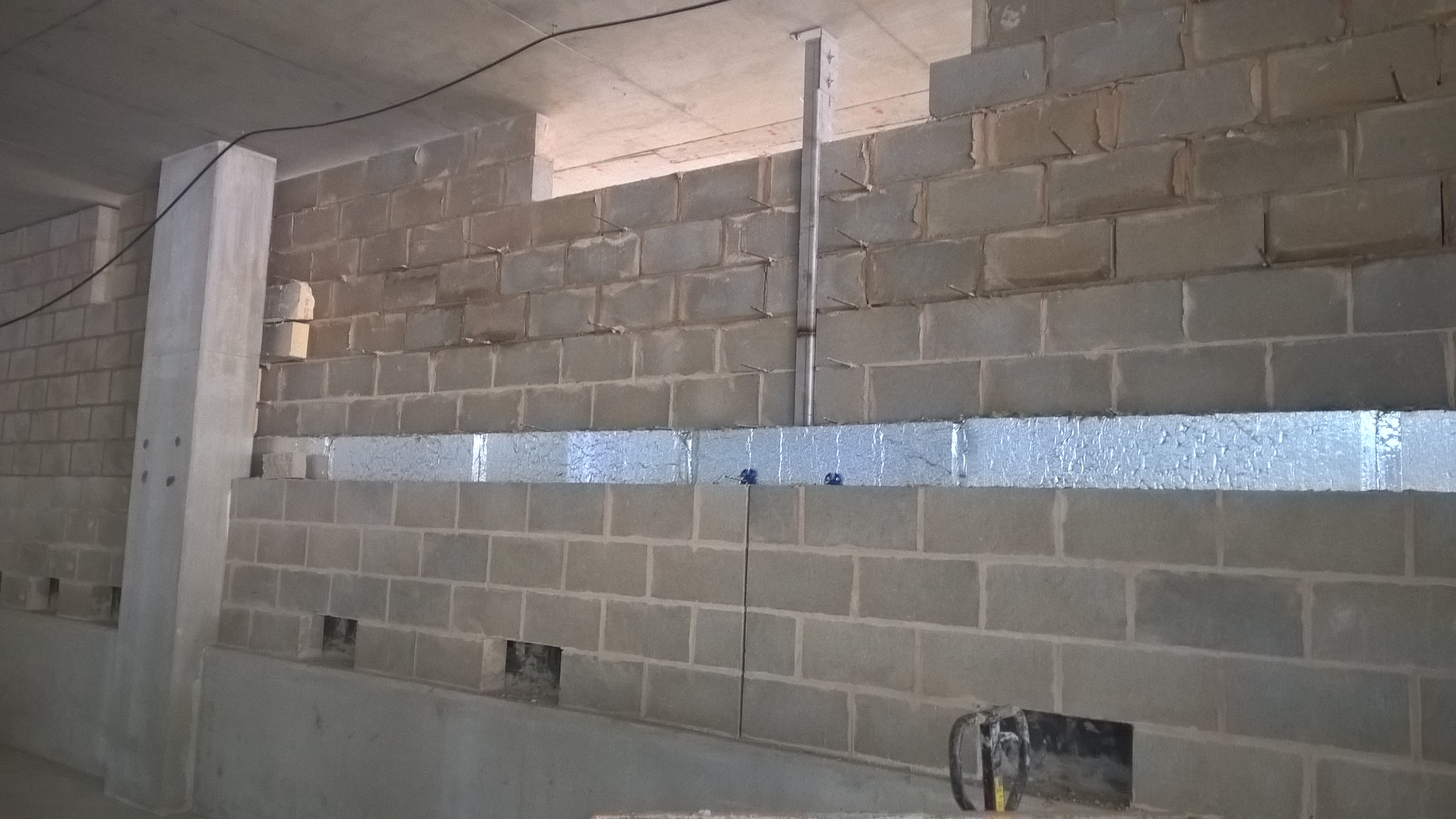
The next evolution of the blockwork saga takes us into the construction of a double skin wall that separates the car park area (a class 2 basement) with the clubhouse area (a class 3 basement). The difference in the classes comes down to a range of measures intended to make the space more inhabitable, such as ventilation, acoustic insulation and (the focus of this rant/blog) waterproofing.
Waterproofing is hugely important to the client because it you don’t get it right first time it cost loads of money to put right. Since SRM would ultimately foot the bill, there has consistently been a lot of pressure to get it right.
The clubhouse area has an additional waterproofing measure in the way of a cavity drainage system. The system interfaces with the block work wall as shown below:
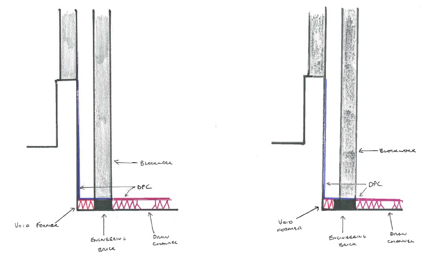
It’s worth noting that this does not align with the architects drawing, or the waterproofing designer’s drawing. But it does reflect reality and therefore I’m building it that way.
Now onto the point about questioning the design…
The bottom of the inner skin is sat onto engineering brick. The bricks are 205mm long and the blocks are 140mm wide. Therefore the bricks were to be cut down then laid side by side (as opposed to end to end) to give a 140mm strip to lay the blocks on. At the base of the cavity there is a void former that the dpc runs over the top of. So why are we cutting the bricks down? Cutting the bricks would cost more and take longer, and you also have to pay for more void former. I suggested laying full bricks to the architect and he was happy for us to do so, as was the waterproofing designer. So why did the additional design call for the bricks to be cut? Because the architect thought the drawing looked neater. I wish I was joking.
So to hark back to Damo’s point, I’ve just saved money by saving time without affecting quality.
The other example is that the inner skin will be dry lined, the only bit of block work that will. Yet the design still calls for paint grade block work. Why? It isn’t painted! I think I remember Pete having a similar thing with a ridiculus concrete finish on a bridge pier that would only ever be seen by a dingo…
In the beginning we had a lot of quality issues with the block work so we’ve got piles of blocks all around the place that we’ve taken down. So I’ve had it agreed that I can use them for the inner skin since it won’t be seen. So I’ve saved material and therefore money without affecting time or quality, and for good measure I’ve wrapped it in sustainability by reducing waste.
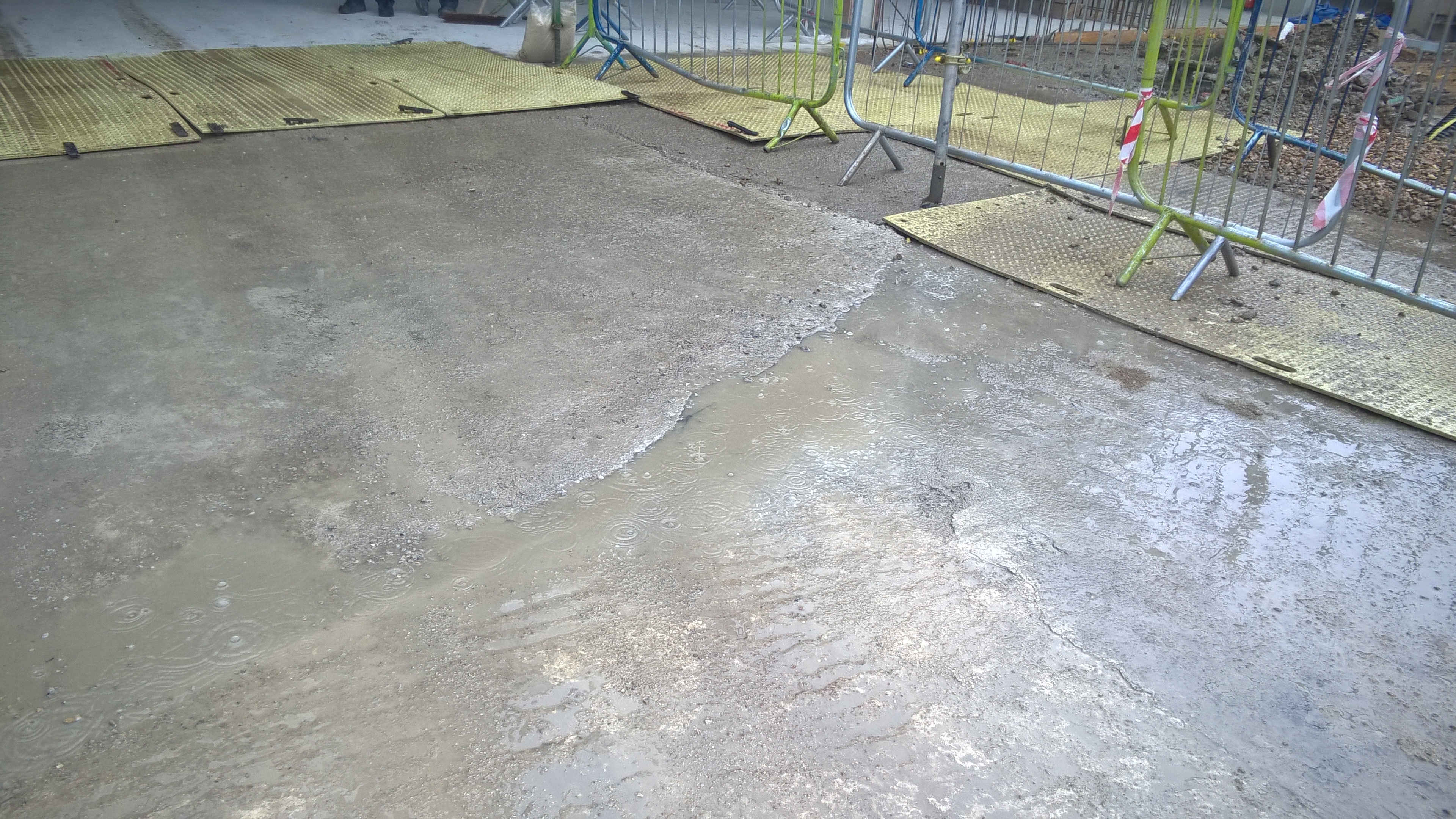
When it rains…
About three weeks ago on a Friday it rained a lot and our site flooded. I’m not exaggerating when I say that most of the basement was under two inches of water. The tower crane bases all flooded and so the power was cut off to avoid electrocuting anyone just before the water reached the junction box.
About a week before we’d seen this coming and so devised a plan to use submersible pumps to cross pump water from the sumps into nearby gullies to get all the water to one place and pump it off site from there. All it needed was five 2″ pumps and one 3.5″ pump.
Despite me personally briefing this plan to the logistics sub-contractor and giving him a copy of the drawing he only had on site four 2″ pumps. It didn’t help that in my original plan I’d not considered two fairly important points:
- Podium slab penetrations. Incredibly I’d actually thought about this and still messed it up. I got out a drawing of the podium (ground floor) slab and ensured all the podium level service penetrations had been waterproofed. I even considered all the light wells and ensured that where up-stands in the basement were incomplete they were sandbagged to keep the water on the correct side. But I’d done it from a drawing. A drawing that didn’t show the massive holes in the slab that the tower crane pokes through! And stupidly I didn’t get off my ass, wander out onto site and have a look there. Thus the issue with the tower cranes!
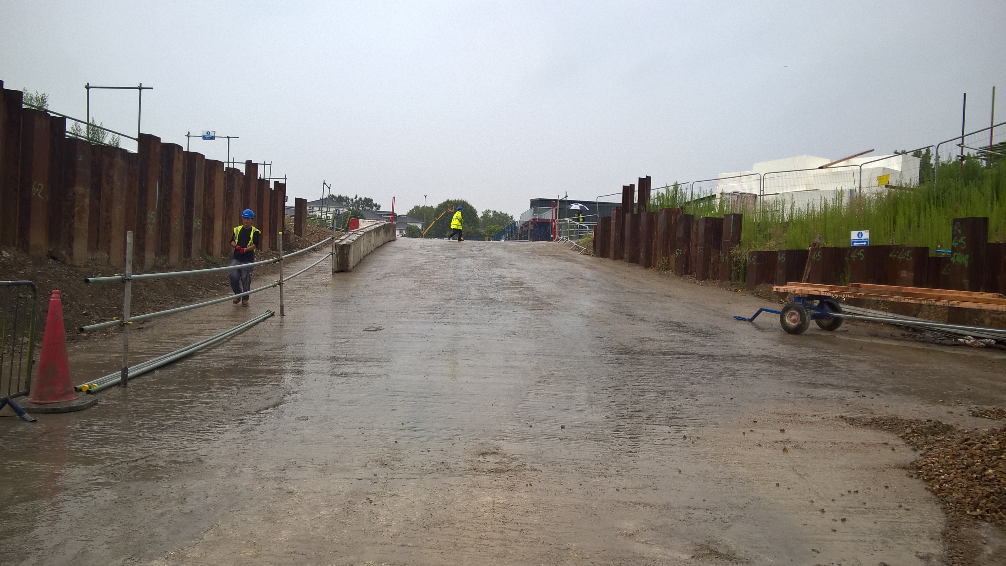
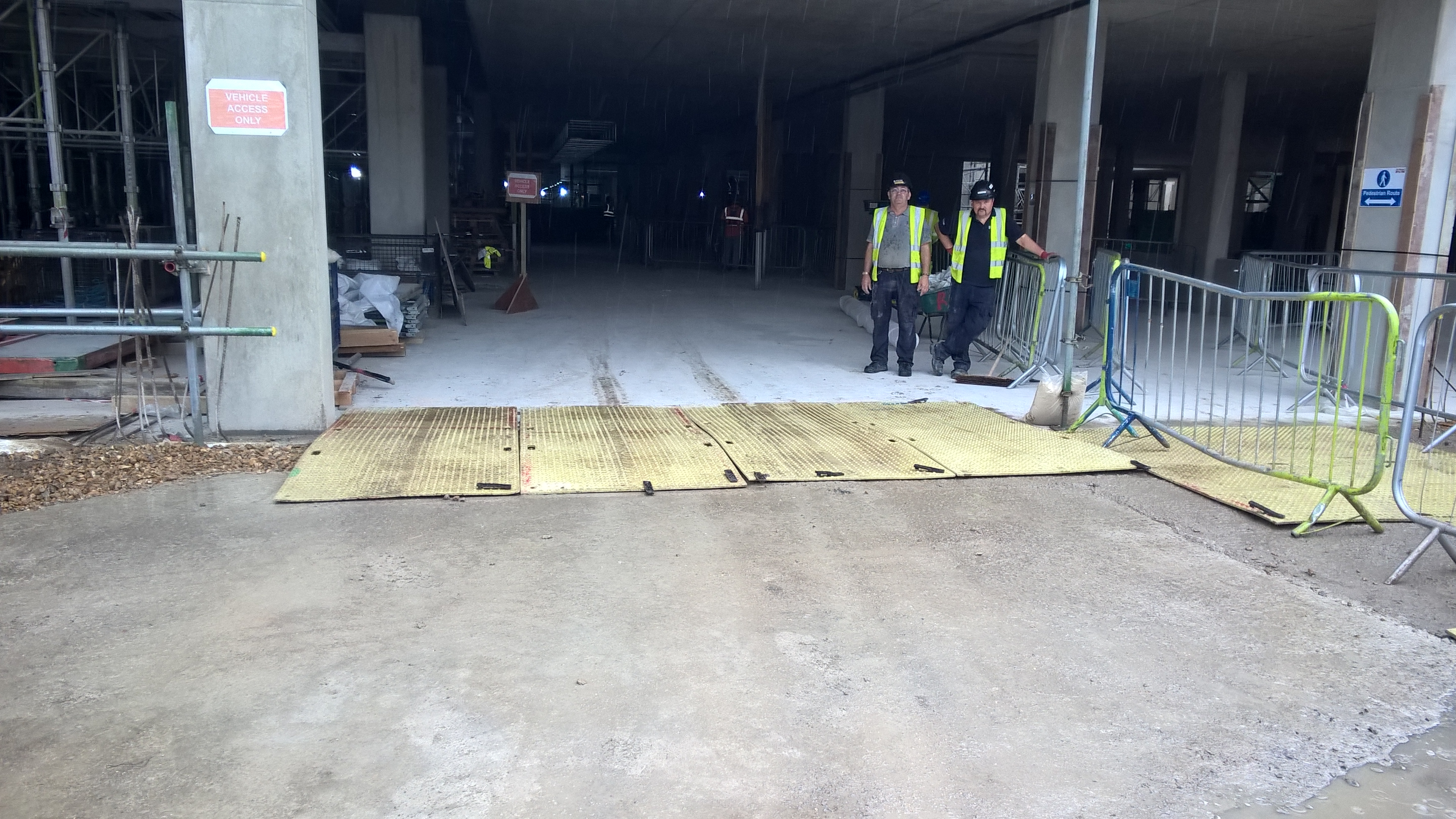
- The ramp. Logistically, and unusually for London, our site is a gift! We’re currently developing about 20% of the old Earls Court exhibition centre car park. Leaving the other 80% for logistical space and offices and the like. We’ve then got a large ramp that leads from the log area to the basement level. What I’d failed to consider is that every drop of rain that landed on that car park made it’s way down the ramp. It was like Niagara Falls (see Brad’s blog for images)! We were simply unprepared for that amount of water flowing onto the slab in that location.
The Monday after “The Wettest day” the construction manager sent out an email detailing what addition measures were to be taken and by who. My job was to ensure the podium drainage penetrations were connected to the basement drainage system with the topside waterproofing removed and that the tower crane penetrations had sandbag bunds around them. I completed my jobs that week. Our services manager was tasked to put a trench across the bottom if the ramp to divert the water somewhere other than straight into the basement. He didn’t bother. I had noticed this by kept my nose out of fear of upsetting anyone. I get enough grief from my project manager as it is – he is very angry and for some reason hates me!
Fast forward to yesterday and on my way to work I read the news on my phone. I saw the headline “month of rain expected in 48 hours”. “Wow, that us not good news!” (Or words to that effect) I said aloud, much to the surprise of the old lady next to me on the tube.
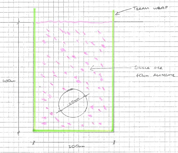
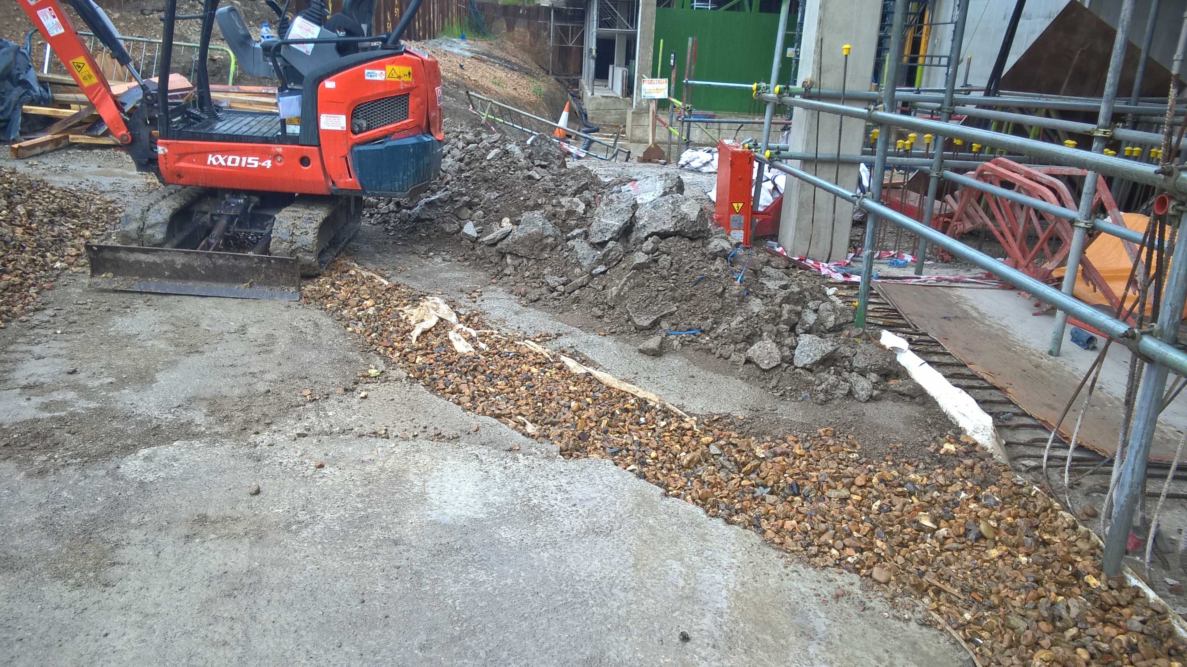
When I got to work I stopped worrying about offending anyone and just set about making it happen. I got a trench cut across the bottom of the ramp. I ordered some teram and 20/40 (aggregate sized between 20 and 40 mm – apparently getting single sized aggregate is pretty difficult these days!) to be delivered the same day. I got a plastic duct left over from installing the tower crane cables and had some holes drilled in the sides. I put the teram in the trench, stuck in the duct, back filled with the shingle and linked the end of the duct into the surface water drainage system that links phase 1 (our bit) to phase 2 (the bit the other side of where the ramp is).
So come the day of the biblical downpour and it hasn’t come. Sure it rained a bit about lunch time but nothing requiring us to put two of every trade onto a large boat (bar the QS’s who gave me loads of abuse for spending more money doing this than it would’ve cost to actually build an arc). But the system is working, the basement is dry and definitely has much more capacity than is currently being used. So I’m taking solace in the fact that it worked. It may not be pretty, it may not be high tech engineering, it may not have required a Microsoft Project printout on A1 paper, but it worked.
Lessons:
- Don’t do anything just off a drawing, get off your ass and have a look – my bad.
- You’ll still probably miss something anyway, so just deal with it the best you can when it happens.
- French drains work.
- Never trust the Met Office.
Making Neil proud
Today I have spent the vast majority of the day designing a bit of scaffolding. The scaffold will be used to attach a “Considerate Contractors” banner so that it can be viewed from the neighbouring railway station platform. It would be particularly embarrassing if millions of pounds worth of disruption to the railway was caused because a “Considerate Contractors” banner blew off it’s support and landed on the tracks. So no pressure then!
I started by considering the forces involved. Essentially the scaffold is required to hold the banner in place against wind loading, at which point I groaned at the thought and opened EC1 and the NA. After considering the elevation, distance in land, urban environment and all those other factors I hoped I’d never need again I then stumbled onto the clause regarding signs. Clause 7.4.3 gives you a coefficient to use when designing signs and the like. When applied alongside the seasonal factor for the length of time it will be in place it gave me a total wind load of 0.853 kN/m2. I checked it with Sam (our resident CEng) who said it seemed about right but that he’d never designed anything to EuroCode in his life.
My next step was to ensure that we could connect it to the scaffold. So I fell back on a skill I honed in Exercise Rhubarb Creek: I googled it. A 3M (TM) “Standard” Cable Tie has a breaking strain of 220N. I did a quick bit of maths and found that one tie would hold down a banner 190 metres long. Then I noticed it was in N not kN. So I had another go. 190mm, that’s more like it. The banner has holes every 450mm, so I needed to go bigger. A “Light Heavy Duty” Cable Tie has a breaking tension of 530 N. Each pair will support 460mm, so a tie top and bottom through each hole will hold it back.
Next came the scaffold itself. I decided on a horizontal bar top and bottom of the banner attached to 4 vertical bars at 2 metre centres. I tried desperately to work out the friction from a screw jack, but to no avail. So instead I just specified that each jack should be bolted to the slab/soffit and specified a bolt using the manufacturer’s data.
And there we have it. I’ve designed some scaffolding! They’re going to build it next week, I really hope it doesn’t blow away!

