Archive
Unforeseen consequences
This blog post summarises the unintended consequence of an energy optimisation measure and explains the chosen method to solve the issue.
Pool water recirculation pumps make up about 50% of the pools electrical energy demand, interrogating a pools recirculation rate can reveal unecessarily high turnover rates set during commissioning. Through the use of inverters (or the use of electronically commutated variable speed motors) it is possible reduce the frequency and speed of the pump allowing reductions in the power drawn thus enabling energy savings.
However, as was the case with the pool in question, a reduction in the recirculation rate affected the pool makeupwater control strategy i.e the pool water level dropped below its setpoint. Due to spatial restrictions this pools balancing tank is set lower than the height of the pool and a separate makeupwater tank could not be installed. Usually a makeupwater tank is separate to the balancing tank and is set at the level of the pool water. This balancing tank has been used for two purposes, the first to allow for ‘spill’ whereby swimmers enter the pool and increase the height of the swimming pool water and the second to allow for makeupwater injection.
The flow diagram below explains sequentially the consequences of reducing the pool recirculation rate to realise energy savings.
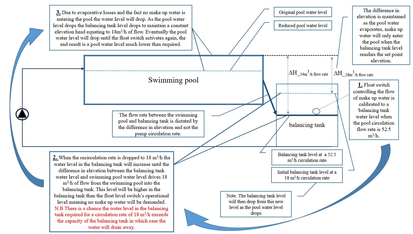
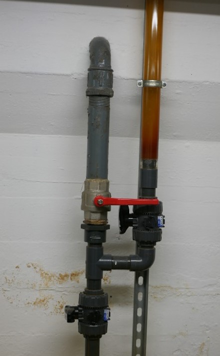
The chosen solution has been to seal the balancing tank and install an automatic air vent thus creating a closed loop system. There is an existing ‘siphon’ pipe (seen below) connected to the pool which shows the true level of the pool water, therefore a new float level switch is to be installed in this siphon pipe that will control the injection of makeupwater into the balancing tank via the solenoid valve based on the actual pool water level.
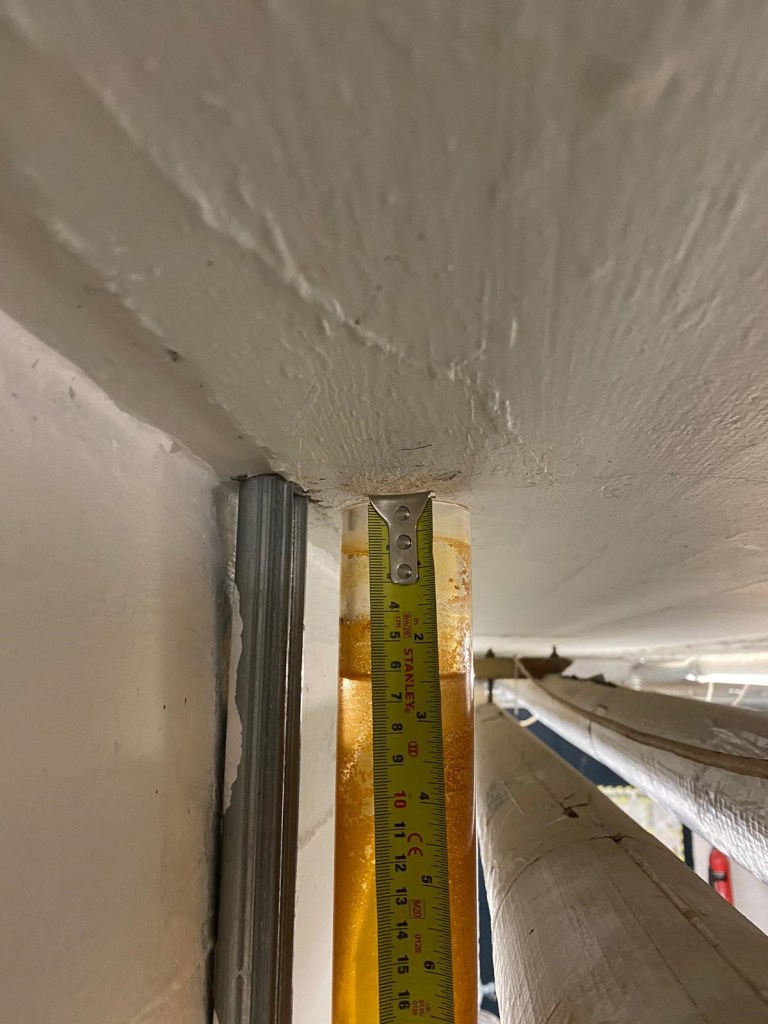
As far as allowing for ‘spill’ from swimmers goes (the function of the balancing tank), it was calculated that even if 12 120kg swimmers (Maximum pool occupancy is 4) entered the pool the water level would only raise by 14mm, this is well below the limits of both the siphon pipe and the pools perimeter construction.
Conservation with Constraints
You have a heritage building with an inoperable Low Temperature Hot Water heating System due to reservicing works, how do you control the internal conditions such that you can be confident the building fabric is preserved, especially throughout the winter period?
Logically you would start by defining what ‘acceptable’ internal conditions are and then formulate a design. The key parameter for preserving the building fabric in a heritage building is ‘relative humidity’ which is predominantly a function of the absolute humidity and temperature. Relative humidity levels greater than 65% cause issues such as mould growth, insect attack and the expansion of hygroscopic materials (a material that readily absorbs moisture) due to the absorption of moisture. Alternatively relative humidity levels lower than 40% cause contractions in hygroscopic materials and ‘flaking or cracking’. It is a lot more complex than this especially when it comes to the conditions required for specific materials in museum archives (not required in this situation due to the widespread removal of valuable objects). Also worth noting is that RH and temperature fluctuations (not more than 10% RH and 4°C change in 24 hours) are undesirable.
For context, nearly all buildings cater to human thermal comfort requirements and typical setpoints of 21°C are specified all year round to ensure comfortable working conditions, the added benefit of this setpoint is the creation of a ‘humidity buffer’ i.e warmer air is able to hold more moisture before saturation and will therefore experience lower relative humidity levels than colder air for the same absolute moisture content. This means that throughout winter your 21°C setpoint will help prevent excessive RH. However, it is not always necessary to provide heat for human thermal comfort, the energy efficient method of ‘Conservation Heating’ (Using heating to control RH) can be used where human thermal comfort is not required and works on the principal that a 6°C temperature differential with external conditions will maintain acceptable RH levels. Essentially conservation heating is used in buildings that don’t require the energy intensive 21°C setpoint for human thermal comfort in order to save energy but still maintain acceptable RH levels.
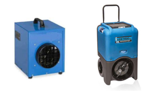
In more recent times, due to the increased emphasis on sustainability the use of dehumidifiers (relatively low energy demand) to control RH has been explored and succesfully employed in numerous buildings across Europe. Typically a dehumidifier requires low infiltration rates to be at its most effective.
The strategy for the building in question (The contractor is adamant about only using 110V electrical appliances to manage the fire risk) is to use a combination of heating and dehumidification units to control the internal parameters. The constraints in the title of the blog refer to the fact that the units can only be operated during the hours 0800-1700 during working days and that the need for asbestos enclosures require the temporary removal of the units from certain areas.
This solution is going to be in-situ for circa 6 months which equates to roughly 1000 hours of operational time. The way the units are used will have significant consequences for the energy consumption and cost of the design. For example, if you had 60 heating units drawing full power during the six month operational time slots you’re looking at a circa £25,000 electricity bill (based on 14.3 pence per kWh).
Ultimately both the units are controlling the RH of the room, the dehumidifier does this directly by reducing the absolute mositure content to achieve a RH setpoint whereas the heating unit achieves this indirectly by heating the room up to a pre-determined setpoint to reduce the RH. The dehumidifier has much better control as it will reduce the RH to the exact level you want whereas the heating setpoint (dictated by the user) will be constant throughout the day and is likely to be ill specified to realise the exact RH you want e.g you could find a situation where a 15°C setpoint reduces the room RH to lower than 40%.
It has been found that the entire building has high infiltration levels, the moment the units are switched off the absolute moisture content of the room equalises with external conditions (If dehumidifiers have been active) and RH increases and the heated room air quickly dissipates (if heating units have been active). Ultimately there is a complete lack of control outside of the operational window. The fan convection units are effective at heating the room air up and not the thermal mass of the building.
Initially a 10°C lower temperature limit for the building was set. Upon reviewing this limit it has been found that up to 400 national trust properties regularly flout this limit with temperatures as low as 6°C in order to maintain acceptable RH levels (Using conservation heating). Due to residual heat gains the building is only expected to drop as low as 8-9°C, coupled with the lack of human thermal comfort requirements and the reduced energy intensity of dehumidifiers the argument can be made that the convection heating units are unecessary.
It would be interesting to have trialled a range of different heating units such as oil filled radiators, radiative heating units and storage heaters to see how effective they could have been at heating the thermal mass of the building and maintaining out of hours control. It is my belief that fan convection units are poorly suited to the task of controlling RH levels in a heritage building and that the dehumidifiers should be the principal means of RH control as they achieve the same effect and with reduced energy consumption.
Effectively controlling the parameters 24/7 in light of the constraints specified in this blog is like entering a boxing match with both hands tied behind your back. Based on the data that is accumulating I envisage a compromise can be made between the constraints and the preservative requirements of the fabric.
Art of the Possible
I blogged a while back about the potential for dispensing with the need for generators by instead utilising the existing grid connected electrical infrastructure to power a winter environmental control solution for the ‘East Wing’ (Convective heaters and dehumidification units). The spare capacity in the infrastructure is due to the reduced footfall and activities on site a la COVID, with some quick analysis of the Building Management System data it was found that there would be sufficient capacity to provide most of the temporary heating electrical demand.
The cost of generators on hire and the fuel as well as the noise and the associated carbon footprint are undesirable given the cheaper and cleaner (carbon footprint per kWh, getting better and better) supply of elecricity from the grid.
Essentially the ‘East Wing’ has two zone distribution boards at the North and South end, both of these boards have 400 A three phase incoming supplies, therefore each distribution board can theoretically draw 276 kVa based on 400 A per phase loading with a phase to line voltage of 230 V. There are 6 floors to provide environmental control to with each floor having different loading requirements due to ‘high risk’ areas in terms of conservation etc.
We toyed with the idea of setting up a system whereby generators would be joined in parallel with the existing electrical infrastructure, the idea being you would maximise the grid capacity from the distribution boards and use generators to ‘top up’ any additional power requirements in the event of surplus demand. We were informed by contractors that to parallel generators up with the grid requires DNO (District Network Operator such as UKPN) permission, takes a long time and costs a fair amount of money (there is also no guarantee that the DNO will provide permission).
Therefore it was decided to match specific ‘high-use’ floors to the distribution boards which turned out to be the groundfloor, principal floor and second floor and the remaining floors would be supplied by dedicated generators. It has already been noted that the kVa demand of each floor has been based on no diversity i.e worst case scenario that all convective heaters and dehumidification units are turned on simultaneously. It has been confirmed that there are spare ways on the Medium Distribution Units to the three floors just mentioned which gives us flexibility if it becomes apparent that the diversity assumption is ‘overkill’ and we can extend the provision of grid power safely across more of the floors.
Also worth mentioning the ‘East Wing’ has been split into North and South zones for geographical convenience in terms of cabling and voltage drops from the zone distribution boards.
Potentially a blog post soon looking at the temperature and humidity levels in the building and the optimisation of the solution, just waiting on access to the environmental monitoring database (temperature and humidity sensors positioned across the floors).
Translating Technical Documents
I was wondering if anyone had any advice on how to translate large technical documents to a high standard whilst maintaining the original formatting and pictures etc. Google translate is the only free software I can find and the standard and quality of translation isn’t good enough.
You’ll Need a Circa 700 kVA, £784,000 Temporary Heating Solution to Deal with Winter Conditions!
Replacing the East Wing Low Temperature Hot Water (LTHW) or ‘heating’ system in a Listed Building context isn’t straightforward, the key element examined in this blog post is the provision of temporary heating. During the winter period it is critical that the building fabric temperature is adequately controlled to reduce the risk of condensation and the destructive consequences.
You could build an entirely new LTHW distribution system to provide heat whilst you replace the old system… this has been discounted already due to cost and complexity. The chosen solution is to power electric heaters and dehumidifiers, bearing in mind there are approximately 200 rooms across 6 floors (basement, ground, mezzanine and so on up to the attic) to provide heat to.
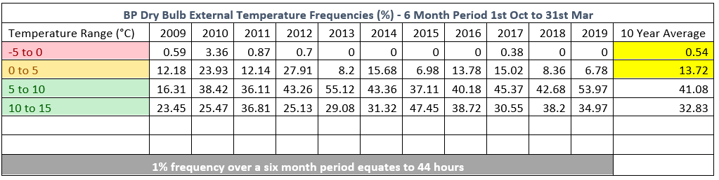
The conservator on site has explained that the building fabric/internal temperature must be maintained at >= 5°C to manage the risk of condensation and building fabric damage. Due to fire safety measures doors need to be shut at night, doors cannot be altered to allow cable runs underneath them, therefore the current solution revolves around the hope that the rooms (old, large rooms with large single glazing windows) retain sufficient temperatures throughout the night when the heaters have to be withdrawn from the rooms to the corridors and operated through closed doors… The contractor in charge of the electric heating system articulated that ‘the London ambient temperature doesn’t often drop below 5°C in the winter and the building usually retains its heat quite well’. I am pessimistic about the ability of the rooms to retain the heat, we are still waiting for detailed heat loss calculations from the principle designer.
The table I collated below disputes the ‘doesn’t often drop below 5°C’ assertion, over a 10 year average from onsite external temperature data it can be shown that for approximately 14.26% of a six month period the external temperature will drop below 5°C. The passive fabric heating effects of a LTHW system cannot be relied upon to maintain the buildings usual thermal mass, the rooms could haemorrhage heat due to infiltration and the current solution cannot remedy this at night time. Rather than trusting in belated heat loss calculations I believe it will be necessary to carefully monitor the rooms heat retention capabilities via existing temperature monitors and we should be prepared to upscale/adjust the heating solution (or relax certain constraints if possible) where necessary.
Moving onto the power supply… the contractor has supplied a quote for plant hire (heaters, dehumidifers, generators) and power infrastructure (cables, installation, maintenance, operation, refueling etc.) based on a perceived 700 kVA load, no diversity has been designed for as it has been assumed that worst case scenario is all heaters are required at the same time.
At normal operating capacity the building in question draws approximately 550 kVa at peak loading (Lunch time). 12 months ago when the building was at full occupancy (Pre-COVID) and the primary transformer and CHP hadn’t been upgraded it was decided that the power supply for the temporary heating should be self-sufficient and was based on a generator solution with a cost of £188,700 from Oct 20 – Apr 21.
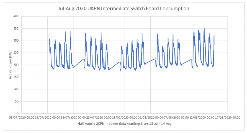
We now find ourselves with a 250 kVA CHP unit and a transformer rated at 866 kVA that could comfortably be loaded for extended periods of time to 120% of its rated capacity (1.039 MVA). The building is now only experiencing 400 kVA (Assuming a p.f of 0.7 and based on the monthly weekday average loading profile between 0900 and 1500 during maximum usage) loading at peak times as per the meter data analysed below from the Building Management System.
With an infrastructure spare capacity of 600 – 850 kVA I believe there is sufficient scope to incorporate it as the temporary heating baseload with generators for peak loads and as the secondary means of power supply in the event that the building loads increase with a return to normal occupancy levels.
Again this is something that is now being looked at in more detail in an attempt to reduce generator usage and the associated carbon emissions and cost of hire and operation, this means more design work for the contractor in terms of safely loading and integrating with the pre-existing electrical distribution system.
As of today it has been decided that the use of a stealth generator or a battery pack solution for night time operation (Where the battery solution would have cost in excess of £200,00) are not necessary and that the existing infrastructure will be utilised… a step in the right direction.
Is the Target Flawed? (≈ 5 minute read)
As 1 of 12 benefits forming the business case for the current project I’m working on it was identified that the installation of more efficient primary plant (CHP and boilers) along with more sophisticated and energy efficient control systems, pipework insulation, wireless thermostatic radiator valves (TRV) etc. would reduce the carbon emissions of the building.
Based on the improvements mentioned above and gas and electric meter readings of the building it was estimated from the antiquated 2017 SAP carbon intensities (0.218 kgCO2/kWh for gas and 0.399 kgCO2/kWh for electricity) that a saving of 554 tonnes of carbon per annum would be achieved, this figure is enshrined in the business case and needs to be met.
Flaws…
The project identified that the building was insufficiently heated and has upgraded both the capacity of the primary plant and the pipe sizes to accomodate faster mass flow rates and therefore an adequate delivery of heat as per the only equation I remember from phase 1, Q=mdot*Cp*DeltaT… joking of course.
More heat at a better efficiency = net carbon emission increase or decrease?
The metering strategy within the building is crude with little sub-metering, coupled with the fact that the occupancy patterns and building use are highly variable increases the difficulty with assessing in any detail the realisation of the target. It was also found that the lack of insulation on the pipework was actually relied upon in some areas (Like underfloor heating) to heat the bulding fabric. Therefore by introducing pipework insulation you’re reducing the heat losses in one place (the pipe) which increases the heat demand in other places (the emitters/radiators) to compensate for the removal of the indirect heating effect. Maybe there is a net reduction in consumption from the pipework insulation, no detail exists yet.
When the target was set there was no methodology for how to track and measure its achievement, no appreciation for the diffculties involved in being able to state, with a high degree of surety, this target has been met. It is assumed that the blanket energy meter readings will be looked at when the project is finished and the hope is that they’ve reduced by 554 tonnes of carbon…
Mission creep has led to enhancements and improvements that compromise the carbon target. Design ommissions such as the removal of wireless TRVs and large scale PV arrays just increase the burden for whatever solution (Likely a closed loop heat pump) is decided upon to address the delta in the carbon target.
Was the target SMART. Specific? Yes, Measurable? Yes but with sophisticated sub-metering and an accurate baseline with extensive data to start from. Achievable? Mission creep with a lack of cohesion across the programme may have resulted in net carbon emission increase, the data isn’t there yet.
White lies? Lets say your overall carbon emissions increased from 100 tonnes to 200 tonnes, but the plant you are now using is 93% efficient whereas before it was 75%. The argument could be made that as a direct result of having higher efficiency plant, the saving you have realised over the original plant is 18 tonnes of carbon, irrespective of the net carbon emission increase. The original wording in the business case was ‘reduce emissions by 554 carbon tonnes’ not ‘achieve a net carbon emission reduction of 554 tonnes’.
Whilst I see the importance for Bottom Line up Front business cases, in this situation the lack of detail with no technical justification completely discredit the benefit and the pressing environmental need for reduced ‘NET’ carbon emissions.
Food for thought.
Writing an Effective Scope of Services – NEC3 Professional Services Contract
I’m currently in the process of preparing an Invitation to Tender for six sustainability consultants. My first task is to create a suitable scope of services within the framework of the NEC 3 PSC, which I’ve completed in draft form, I’m waiting out for feedback from the procurement and contracts manager. In the meantime I was wondering if anyone had any advice or experience they could share regarding writing an effective scope of services?
Would Photovoltaics Cut the Mustard
The sustainability goal for the project I’m currently working on is a 554,000 kgCO2 (554 carbon tonne) emission reduction per annum, and it is to be achieved by project completion. Due to two late design ommissions of wireless thermostatic radiator valves and large scale photovoltaic arrays it is projected that this carbon target won’t be realised. To offset these ommissions it is suggested that a heat pump be utilised to provide low grade heat to a suitable application: which the design consultant has identified as the on-site swimming pool hot water demand via two existing plate heat exchangers. To amplify the carbon savings of the heat pump it has been suggested that photovoltaics can be used to provide the electrical demand of the heat pump, there are no explicit calculations to support this assertion.
Design consultant calculations:
Between 38 – 58 kW water heating demand based on modelling software.
That is all the design information that the consultant presents, below are some of the questions that I’ve worked my way through to arrive at an overall conclusion.
Small Selection of Heat Pump Specific Questions:
Can the consultant software be relied upon?
Can I validate their hot water demand calculation with an energy balance equation?
What local viable heat sources are there?
What are the seasonal temperature profiles for each source?
What are the theoretical seasonal co-efficient of performance (SCOP) associated with each heat source?
Why use SCOP? Does the heating demand of the pool vary with the season?
What is the real SCOP likely to be based on empirical evidence?
Is the hot water demand of the pool constant? 24/7? all year round?
How do I obtain an electrical energy load profile for the heat pump?
Won’t the electrical demand of the heat pump vary with source temperature profile?
What should I consider to determine worst case operating conditions (Highest electrical demand for the heat pump) i.e highest flow temperature required, coldest heat source temperature, lowest plate heat exchanger efficiency…?
Small Selection of Photovoltaic Specific Questions
What determines the viability of a photovoltaic solution: cost, land required, installation practicalities, servicing requirement?
Is battery storage necessary and if so how will it be designed to modulate the electrical supply and demand between the PV array and heat pump?
How can I best estimate the annual PV energy yield of different sized systems?
How can I validate the PV energy yield software/calculations?
Can I utilise a two-axis tracking system? Would the extra cost be offset by the increased annual energy production?
In a nutshell: Due to space environmental set point temperatures, the swimming pool hot water demand can be approximated as constant all year round with the energy balance equation resulting in a loss of 31.2 kW (Mostly through evaporation and mains temperature renovated feed water). The best heat source is the lake due to the highest SCOP, the COP for the lake can drop as low as 2.6 in winter conditions with a corresponding heat pump electrical requirement of 12 kW. Based on the SCOP (for the highest flow temperature of 65°C, SCOP = 3) the annual electrical energy demand is ≈ 96,000 kWh, with an average electrical requirement of 10.4kW. For a monocrystalline flat panel PV array in London, with a 180° azimuth, 33° tilt to the horizontal, module efficiency of 19% and no shading losses an area of ≈ 500m2 is required to provide the average annual electricity requirements of 96,000 kWh. That area requirement exceeds the space offered by the swimming pool roof, and adding into contention the significant shading losses (Due to nearby buildings) and sub-optimal orientation angles from the slope of the roof, it would be necessary to either increase the size of the system or relocate it (introducing the potential for significant voltage drops and increased cable size and cost)
The added complexity of utilising battery storage to modulate and supply the varying electrical input from the PV array to the heat pump would be the next steps to assessing the viability of the coupled system.
In short, the consultants assertion is likely to be impractical.
COVID-19 Expedient Medical Facility Options Analysis
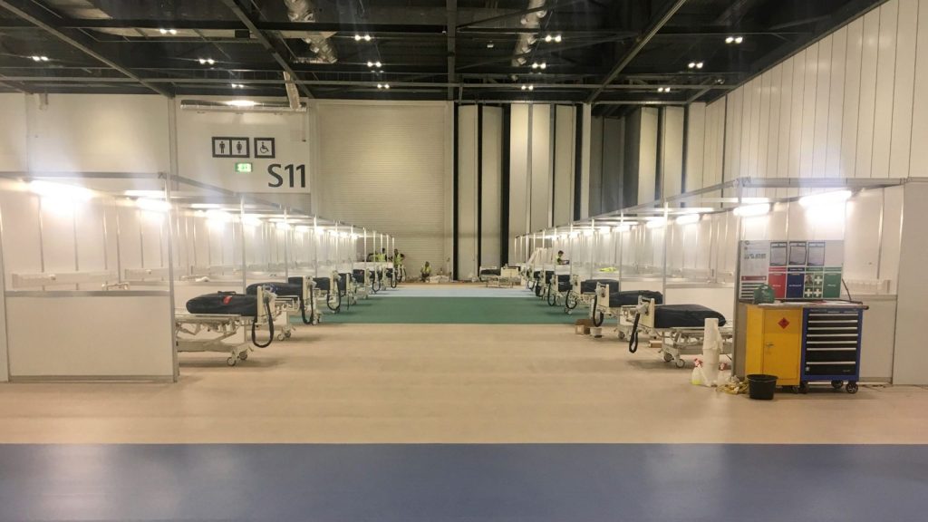
Balancing the requirements of producing an expedient medical facility that provides sufficient overflow capacity whilst achieving the medical and engineering standards for treating COVID-19 positive patients is not an easy task. Compromise is necessary and is evident in the construction of the impressive Nightingale Hospitals that we are all familiar with, see below for a recent blog post by Jamie B.
Over the past couple of weeks I’ve conducted research into the epidemiological nature of COVID-19 and the corresponding medical and engineering requirements in order to conduct analysis and appraise alternative solutions for providing expedient medical facilities. The findings shed some light on the rationale behind the NHS Nightingale Hospitals and the potential for implementing different medical facility options.

The provision of engineering infrastructure should be dependant on the medical requirements for effectively treating COVID-19 patients whilst preventing the further transmission of the virus to health care workers.
However, there is a clear divide in medical guidance for managing COVID-19, this stems from the international community of virologists uncertainty over the causative pathogen SARS-CoV-2 and its exact mode of transmission, is it airborne? Initial research is inconclusive and the jury is still out.
This uncertainty has led to two distinct epedemiological schools of thought for managing COVID-19 patients, the cautious approach and the less cautious approach. The European Centre for Disease Prevention and Control and CDC (US counterpart) strongly endorse the provision of single patient negative pressure isolation rooms with en-suite facilities for confirmed COVID-19 cases requiring admission, where this isn’t possible cohorting of patients is recommended. Whilst the UK Government and WHO state that negative pressure isolation rooms are only required for Aerosol Generating Procedures such as intubation and cardiopulminary rescucitation due to the increased risk of airborne transmission.
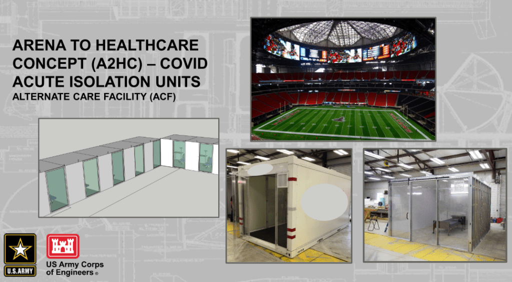
Therefore there is variance in the way governments have chosen to approach the provision of COVID-19 surge capacity medical facilities, see the figures above.
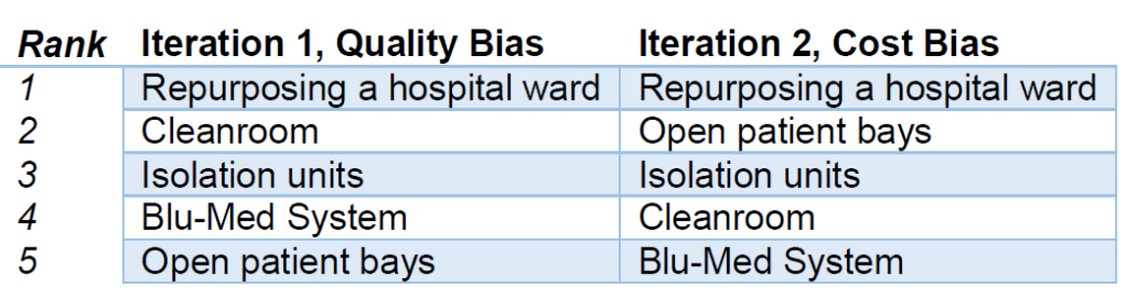
My analysis of the different options has been based on the selection criteria a-f below. I conducted two iterations of a multi-criteria decision analysis (MCDA, a technique used for complex decision making) which allowed adjustment of weighting values, the first with a quality bias and the second with a cost bias (See MCDA findings below). The six distinct options chosen for evaluation were: Repurposing hospital wards, in-Situ construction of isolation units (Design similar to the USACE concept drawing), pre-fabricated cleanrooms, blu-med tented systems and the Nightingale open-patient bay design. See the one drive link below for the full study.
a. Infection Prevention and Control (IPC) Precautions. There is significant variance in the recommended IPC precautions due to the exact mode of transmission being unknown. Systems will be judged on how well they satisfy the most stringent precautions.
b. Ventilation. The system must provide ventilation in accordance with medical guidelines, designed correctly it can contain and mitigate the spread of pathogens amongst other important capabilities.
c. Power. Healthcare electrical installations must provide maximum reliability and integrity of supplies. The ideal facility will have a minimal probability of equipment failure due to loss of power.
d. Construction Time. The medical facility must have realistic construction timelines to meet surge capacity demands.
e. Cost. A key driver in all construction projects, the solution must provide benefits that are justified by the cost.
f. Surge Capacity. The solution must be capable of providing suitable patient capacity to meet surge capacity demands and have a resilient supply chain to ensure operation in the long term.
The findings recommend that in the first instance, general hospital wards should be repurposed to airborne isolation wards. The inherent advantages of locating a COVID-19 treatment facility within a hospital are obvious and there are minor cost-effective changes that can be made to increase transmission control such as adjusting existing HVAC ventilation rates for a negative pressure differential, installation of portable HEPA filtration units to improve ACH within general rooms and minor construction works such as creating ante-rooms and installing germicidal UV-C lamps at entrance points to the ward.
Once existing hospital space has been exhausted there are multiple options. Market research has determined cost per patient of installing a cleanroom ranges from £13,567 – 20,255 per patient with a construction time of 4 person days per patient, whereas it is estimated open patient bays can be constructed at £625 per patient at only 1.5 person days per patient. The IPC precautions and contaminant control offered by a cleanroom are superior (the ones looked at in this study conform to ISO 14644-1 Class 7 and are easily capable of 10 ACH) to the open-patient bay design and UK based companies are offering specialised COVID-19 cleanroom solutions in bulk. As alluded to in Jamie’s blog post it would be extremely difficult to provide adequate ventilation requirements in the ExCel Centre without significant modifications, personalised local ventilation would be needed for effective contaminant control.
Bespoke isolation units that can be constructed in-situ from easily available materials should not be discounted, there are proven designs described in the study that are capable of quick and cost effective construction that utilise portable HEPA units capable of 99.7% contaminant control (referred to as isolaton units in the study). These are scalable and construction materials can be swapped where applicable.
Clearly there are an inordinate amount of factors at play and the nature of the viral transmission is still unknown making decision making more complex, this blog post has only scratched the surface of the engineering challenges of each option. See the onedrive link above for more detail.
This study was completed in isolation with no involvement in the Nightingale hospital construction or COVID-19 planning teams, it is an outsiders perspective. However I hope that it provides awareness of the medical and corresponding engineering issues surrounding the best way to provide COVID-19 expedient medical facilities.
