Archive
You sunk my barge……
I thought you may like the pictures. As many of you know, at the Northern Line Extension we use barges on the Thames in order to remove our muck, fed by a conveyor system from our site.
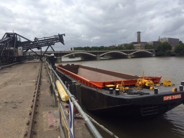
Fig 1. Empty Barge
The capacity is between 1200 and 1600t depending on which barge is being used, measured by the draught of the barge. The draught is measured prior to loading, using draught marks, and monitored during loading so that the weight in the barge is known; as a back up the weight of muck is measured as it goes over the conveyor belt.
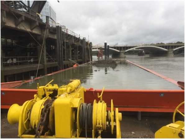
Fig 2 Sunk Barge
So what actually happened? The Lighterman who is responsible for loading the barges was carefully watching as the barge was being loaded, the draught was ok. Despite the ever increasing reading from the conveyor belt read out, the draught was still ok. Once the conveyor belt reading was in excess of 1900t the conveyor belt was stopped, but the draught was still ok……. Turns out the barge was just sat on the river bed so despite what the photos look like, technically the barge did not sink, it just failed to float once the tide came in.
Always Interrogate Loads Part Two!
After Brads post last week I thought I’d jump on the bandwagon and descried a similar load related situation we unraveled last week.
The D-Wall for the Station Box at Battersea was installed last year and contains a number of plunge columns. When installed one of these plunge columns was put in 40mm horizontally mis-aligned, and at an angle amounting to circa 100mm out at depth, then to cap it off the concrete for that D-Wall section was thought to have been poured low.
This results in a design for temporary bracing, to be installed to reduce the effective length during the temporary construction stages.
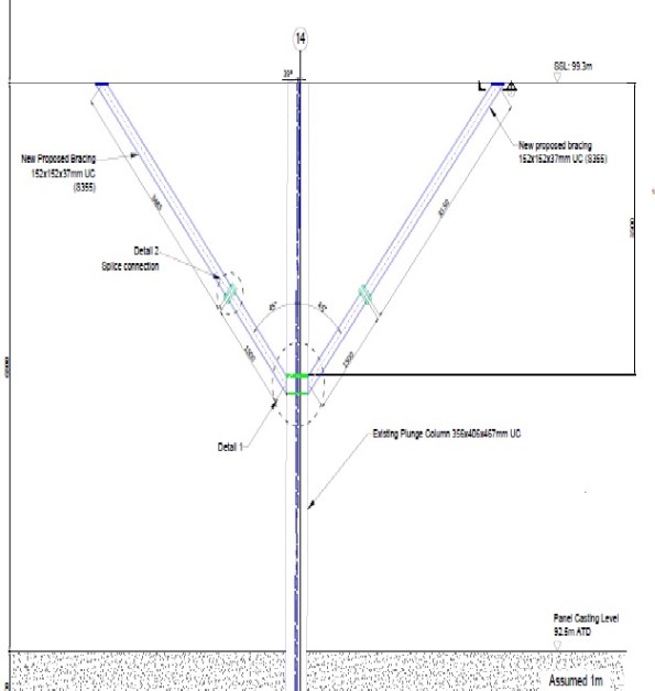
Everyone on site knew this bracing needed to be installed but no one had really questioned why and if there was another method to brace the column. I initially put forward two suggestions:
- Brace the column from the permanent works below, thereby reducing the requirement to lift the UC bracing sections and drill and fix into a soffit at height.
- Why couldn’t we just cast the RC encasement now?
Although I quickly disproved my own ideas it led me to look at the calculations, and the design behind the bracing. It turned out that the column failed in the buckling check by 118%. However the load case on the column included a temporary road/platform which no longer was going to be constructed. This temporary road added 1300kN to the axial load of the column therefore once this axial load was deducted, the column passed the buckling check and the bracing was no longer required. This was subsequently agreed by our TW cell and the Designers.
From a H&S point of view this eliminated the need to conduct a difficult lift inside an excavation, drill and fix into a soffit at height and the construction of temporary works. In addition it saved time off the programme. All this work was going to be conducted because no one had thought to question what we were doing and interrogate the designed for load case for the column.
How quick is base heave?
Battersea Station Box is a top down method of construction; we are currently excavating in London clay and blinding in order to fix steel prior to pouring concrete for the propping structure. The first blinding was poured about 4 weeks ago and what at first we thought were surveying inaccuracies appears to be the concrete blinding heaving. We have excavated about 10m of soil so the total stress will have reduced by about 200kPa.
I believe there are two forms of heave, elastic rebound and swelling. The maximum rise in the blinding is currently about 10mm, and we are now trying to track the rise as it appears to moving about 2-3 mm a week. I am surprised that this is happening over such a short time frame and as we are casting primary beams prior to digging down again we risk the soffits being out of tolerance.
Currently all I can surmise is over such a short time frame it is elastic rebound rather than swelling. Swelling is due to changing effective stress due to unloading and the change in pore water pressure which I would have thought would take place over a longer period.
The GDR only quantifies heave in relation to pile design and the pressure it will apply to the base slab in the long term (drained), it mentions short term relaxation but does not quantify it.
Has anyone come across a similar situation before?
How much reinforcement is too much reinforcement?
I draw your attention to the photos below as an illustration of the problem. It shows the quantity of steel being installed both longitudinal and transverse.

Photo 1 – B40 Longitudinal Bar (The steel coming towards the photo is the bottom longitudinal steel at the end of a beam)

Photo 2 – Transverse Reinforcement

These beams are at the B01 level in the Battersea Station Box, in places 3.8m deep, acting as transfer beams for the over site development. They have been designed for point loads of up to 10MN, transferring the load to plunge columns.
If I now break this into two:
Longitudinal steel – The quantity of longitudinal steel in places is greater than the 0.04Ac. I thought this 4% figure existed to prevent brittle failure and allowed tension cracks to appear in the concrete prior to the beam failing. Therefore, if this is the case then what are the implications of a design such as this?
Transverse steel – Looking in the guidance for the minimum spacing of transverse steel, the distance should be 20mm (10mm aggregate) to form a bond between bars. Clearly this does not, therefore I see three problems potentially arising. Firstly a proper bond will not be able to form between traverse bars; does anyone know what implication this will cause? Does it mean a reduction in shear resistance? Secondly it does not allow for vibrating pokers to be lowered into the concrete at this location during casting and thirdly it acts as a sieve during pouring, causing separation in the concrete. All of which are mentioned in the codes when designing transverse steel.
Looking into the detailing a bit further I discovered in the IStrutE detailing guide, the table below shows the difference between size and diameter of bars. Apparently one should not confuse size with diameter, after all a size 40mm bar is 46mm in diameter. Therefore when this transverse steel was detailed, if the size was assumed to be the diameter, all those millimetres add up to the situation in the photos above.

Slope Stability – Safe or not safe?

Figure 1 – 45 degree slope with 80T crane surcharge
Whilst wondering around site during my first couple of weeks I couldn’t help but notice the slope in the picture situated in River Terrace Gravels. Having now read the GDR I know the design phi dash of the River Terrace Gravels to be 33o. Therefore a design angle of Beta at approx 60o. When I queried a couple of the site/section engineers the response was that they always cut a slope at 45o and then step it if it is a larger slope. The layer below the River Terrace Gravel is London Clay and I would agree that for the short term in clay this would be sufficient, relying on the undrained shear strength. However is the design of 45o in the River Terrace Gravels acceptable?
Firstly a slope cut at 45o would still suggest a safety factor of 1.3, assuming that the pumping of ground water has reduced the ground water regime profile of the water level to below any slip surface. There is a sump reducing the water level to approximately 3m below the toe of the slope, so I will make this assumption.
I modelled this case in Geo5 (Figure 2), producing a result of instability. Geo 5 was showing failure in DC2 but not DC1. This is because DC2 is more conservative where a gamma factor of 1.25 is applied to the tan phi dash, reducing phi dash to 27o. As this is a temporary load case and we know phi dash will not be as low as 27o is this suitable for a temporary works solution?
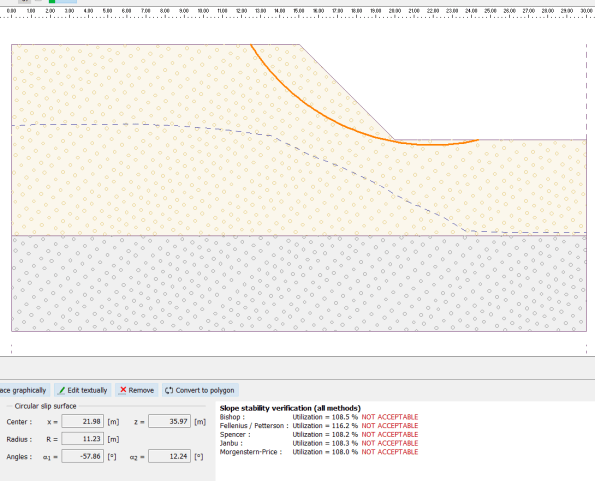
Figure 2 – Slope modelled on Geo 5
Moving on – As you will see in my photos there is a crane (80T) operation at the top of the slope, therefore once you take this load and factor by 1.3 (NA to 1990. NA.A1.2(C)) and re-model in Geo5 you can see it fails with a larger rotational slip. The crane is in fact sitting on a 400mm deep concrete blinding but I cannot model this without Geo 5 ignoring STR failure in the concrete pad. If I ignore the pad then obviously the situation is worse but the principal the same.
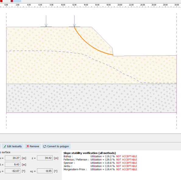
Figure 3 – Slope modelled with surcharge
The gamma factors in the Eurocodes are there as guidance and therefore I would argue temporary works is the ideal time to reduce them if considered safe to do so by the engineer (allowing for other factors). Is this an example of just such time when the ground seems to be behaving as expected or is this too great a risk. However currently there is no temporary works design for this slope and the surcharge inflected by the crane; so I would suggest it is too much of a risk!
