Archive
Oh how I long for Eurocodes!!!
I never thought I’d say this, but I really do long for Eurocodes. Whilst the plethora of EC books for design exercises in Phase 1 may have seemed confusing, whilst being in the USACE office I now realise just how thorough and user friendly they all were. I can almost picture (longingly) the flow charts we used for steel design.
Instead, I am presently hamstrung by a Steel Construction and Design Manual (SCDM) that is 3 inches thick and literally made of cigarette paper. Not only is there no easy flow to the manual and its contents, but it sits in isolation with no sponsored design examples. Instead there are a plethora of Design Guides that are not up to date, therefore do not reference the SCDM accurately. In some case, such as one of my projects (a supporting structure design for overhead cranes), US structural engineers use a Canadian design guide that is more thorough…and to add injury to insult, it uses metric units rather than imperial! Added to that is the choice of which design philosophy to use, and the one you have decided to use may not be the one that the Design Guide explains and/or uses in its design examples. That said, though my design calculations seem to take an inordinate amount of time for me to consistently detangle my knickers, it has forced me to go back to first principles!
Two design philosophies exist in the USA: Allowable Strength Design (ASD) and Load and Resistance Factor Design (LRFD). Both are strength based philosophies, though ASD was historically stress based. My first question was: What on earth is the difference and which one do I use?
1. When considering the steel yield vs displacement graph, the combined force levels (i.e. load, moment shear) for ASD design are kept below Fy, by taking the nominal strength Fu and dividing it by a factor of safety (aka permissible stress design). For LRFD, the combined force levels are kept below a ‘computed’ member load capacity which is a product of Fu multiplied by a resistance factor (aka limit state design ~ Eurocodes!).
2. ASD treats live and dead loads equally, thus uses one FOS for both live and dead loads – this accounts for uncertainty in load and capacity. Consequently it is simpler to use and more conservative. LRFD however recognises the inconsistencies of dead and live loads thus allocates a higher FOS for live loads than dead loads as dead loads are believed to be more accurately calculated…. LRFD also recognises inconsistencies in material properties and construction tolerances.
So, though LRFD is proven to be a more ‘efficient’ approach in that it harnesses more of the strength capacity of a member, legally we can use either method for steel frame design. ASD has historically been significantly quicker than LRFD for preliminary design although recent editions of SCDM have become more thorough for ASD. I honestly believe that having uses ASD, it appears quicker than LRFD (not that I have done the latter yet) but it is still far slower than EC….largely due to the complexity of the Design ManuaI (and because imperial units are driving me insane!) And that is the reason that every engineer has told me why old-school US structural engineers are steering well clear of adopting LRFD (not the units piece).
The same goes for timber and masonry design; concrete is the only one where LRFD is mandated (by the ACI). But to add even more confusion, USACE has mandated LRFD for certain design work such as hydraulic steel structures. Then, I have also found, that product catalogues will vary in what methodology they have used for their allowable loads – this makes things incredibly tedious. All in all a disjointed approach across all the institutions!
Progressive Collapse, and other observations….
Last week I was lucky enough to be sidled onto a 2-day course on Progressive Collapse Mitigation run for USACE structural engineers, organised by American Society of Civil Engineers and delivered by a Californian structural engineer – Jesse Karns. The US defence has spent extensive amounts of money in R&D on this topic, and has encompassed its findings and design approaches for all federal buildings in 2009’s UFC 4-023-03 (Jesse was a major contributor in all these areas). Whilst the UFC is not code, it is a guideline requirement for all US federal construction greater than or equal to three ‘occupied’ storeys.
The US approach had admittedly been shaped by British Standards, so much so that the 2005 version of the UFC was almost a verbatim copy of the BS. However, since then, the US government has invested a lot more money into R&D in this area…admittedly due to force protection risk assessments, combined with increased R&D into seismic issues. I was tickled by a comment in the essay distributed by our very own Atkins secondee: “The UK is currently seen as the centre of engineering excellence around the globe”…really?. Well, after this course and a limited time in the US, I beg to differ. The quote needs some justification, for example – the UK certainly cannot profess to be a centre of excellence on levee design and flood mitigation when Holland sits under sea level with its livelihood relying on flood defences, and the US has over 100,000 miles of levees. Nor can it profess to be on a world stage with regards to seismic design when there is limited risk to design for. Off the back of this, I though I’d briefly blog on the US’s present approach to progressive collapse – where they clearly believe they are the centre of excellence, or is this just engineering arrogance…a bit like why it took 1995’s Oklahoma City bombing and the 2001 World Trade Centre Collapse for the US to really rethink the how rigorous its codes were, despite UK’s lessons from the Fallon Point disaster back in 1968. I digress…
The 2009 version is viewed as a pioneering document that leaves BS and Eurocodes wallowing in design assumptions that are based on weak and outdated research (albeit much of the design methodology has the same basis). I though I’d note the following comments that were in the handout alongside the odd wry smile in my direction …’the mechanics of the methodology are much better defined than British Standards’, ‘the past UFC was based on British Standards and were not too bad for RC (some flaws nonetheless), and really bad for steel’.
So, here’s the lowdown, with some initial figures showing the R&D testing set-up for column removal:
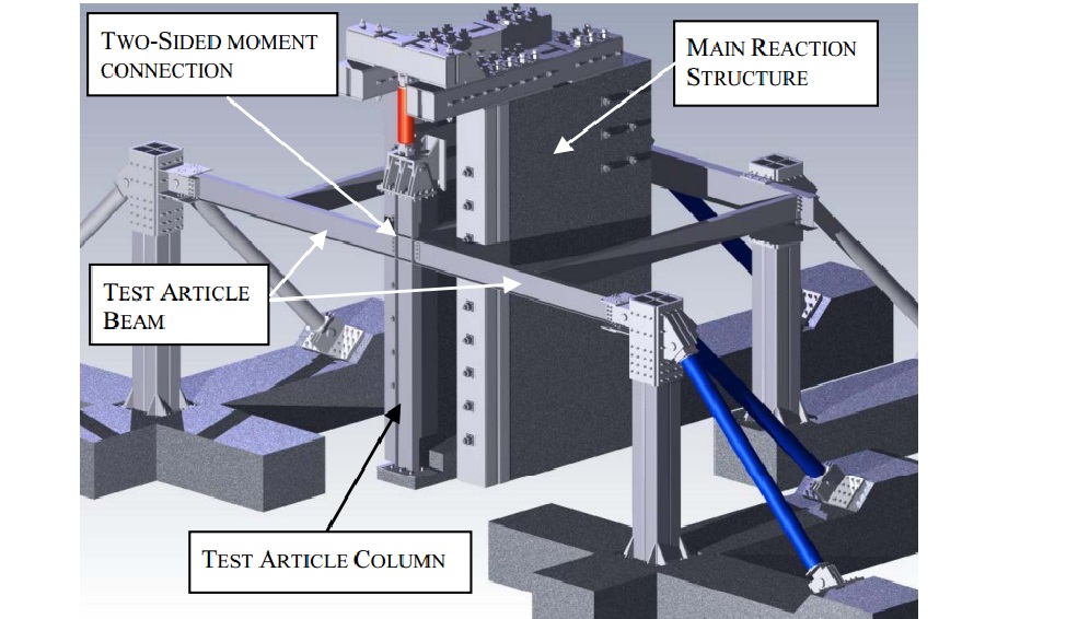
Test model setup for column removal as a result of blast action
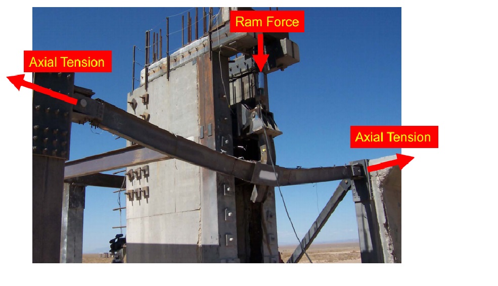
Actual testing post blast (note splayed column)
Design Requirement. As said, the UFC applies to buildings with three of more ‘occupied’ storeys. The design requirements are dictated by an occupancy classification, from 1 to 4 which is relative to consequent impact on loss of life. ‘1’ being structures such as storage or agricultural facilities, and ‘4’ being hospitals, emergency shelters, aircraft control towers. Three design requirements exist:
- Enhanced Local Resistance (ELR). In outline, this is where the shear and flexural capacity of perimeter walls and columns are bolstered for additional protection. It is done to increase the capacity of corner and penultimate columns to resist potential increased lateral forces from tie forces (see below), decrease the possibility that two columns will be removed in an initiating event, and forces a ductile flexural response by limiting shear failure.
- Tie Forces. This British philosophy prescribes tensile forces that hold primary members together. Ties are provided at across each floor level: horizontally (internal and peripheral) and vertically (at columns and load-bearing walls). The theory is based on catenary actions, where internal tie forces are related to beam vertical beam displacement, load and original span length.

- Alternate Load Path. Software design that allows for a localised failure but requires that alternate load paths be available to distribute loads to other undamaged parts of the structure.
The occupancy classification dictates which ones to use e.g. Class 1 – no specific design requirement, Class 4 – Tie Forces, ELR for all ground floor columns or walls, Alternate Load path for specified column and load bearing wall removal
A notable eyebrow twitch came in the results of connection testing. Structural engineers on the west coast of the USA will always design beam-column connections, with detailed drawings. Everywhere east of the Rockies, we just stipulate moments, forces and directions and let the fabricator ‘crack-on’. Why the difference? Well, primarily because of the West Coast’s prevalence of seismic events and the knowledge of how buildings collapse…it has been found in structural studies post 1994’s Northridge earthquake that connection failures have consistently been the cause for progressive collapse. The below graph from tests between 2004-07 identifies the displacement of a central connection directly above a column that has been removed.
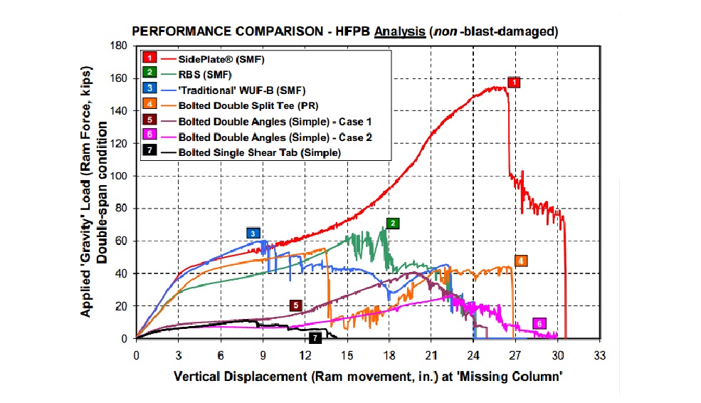
Conscious that we want to harness a beam’s flexural and plastic capacity when considering progressive collapse resistance, allowing it to go into the plastic realm between Fy and Fu (and not beyond), the specific design of connections by an engineer should be essential when considering progressive collapse……
USACE Design Phase – Initial experience
Though staying within the same overall organisation (USACE), my office has now moved 80 miles south. Instead of an hour car ride, it is now a 45-minute train trip direct to the front door of the 10-storey downtown office block, experiencing all the ”sights and sounds” of Baltimore en-route!!
I was initially placed in ”Civil Works” – involved with levee design, stream and coast rejuvenation, waterways, Hurricane Sandy relief ops etc. Some really interesting stuff, but projects were very long-term and I would see little opportunity for tangible design. There were several reasons for that being my initial placement, largely I think as a hangover from Matt Fry’s good works he did whilst he was there, but project opportunities have now changed. So with a few chats and explanation of my DOs I managed to take a swift turn to the right and move to the Military Design Branch.
The Design Branch is 70-strong, with several sections: architecture, structural, geotech, site development, elec and mech engineers with many sub-specialities within each section. The number of projects that the Branch oversees (design, specification write-up and/or review) is immense. At the height of the US Army Base Realignment and Closure programme from 2005, the Branch was only designing 3% of its projects…but the total amount of projects being managed was over US$2billion! Now, on average, the Branch designs about 13% of its projects – the remainder are contracted out and then reviewed by the Branch. $50 Million is about the present capacity for an in-house design.
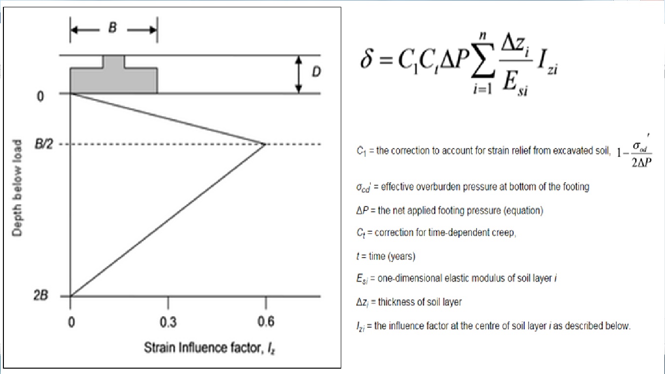
Now targeting my weaknesses – E&M, and Soils…I have already waded into a pump/lift station design, as well as preliminary shallow foundation footing sizing for a US Government testing facility in order to feed into the structural section for further detailed design in due course. The design experience gained in Phase 1 is starting to come to the fore – it took a little while to shake off the cobwebs, but it soon came flooding back (alongside much JM-note referral!). Being able to hold your own with certain specialists, gains credibility and responsibility quickly (that’s what I naively think so far!). To date, the shallow foundation design has been most challenging, particularly due to unit conversion (structural loading in ‘kips’ to name but one!…so I quickly turn everything back into the bosom of ‘kN/m2’), and then running through text books and new ACI codes. ULS design reverts to Terzagi for bearing capacity checks, taking q(ult) and dividing it by a FOS of 3 to get ‘net’ ultimate bearing capacity. For SLS checks, I have been directed to use the Schmertman Method – for those interested, it calculates settlement from layer stiffness data, bearing resistance as well as a time factor for creep (although the latter has had little influence). The method proposes a simplified triangular strain distribution and calculates settlement accordingly; once mastered with an excel spreadsheet, it has been quite a user friendly method to quickly manoeuvre parameters within.
Having attended several design meetings on other projects two things have already become quite apparent:
BIM. Or, the lack of it! There are essentially three different design systems worked on by a design team – Civil 3D by site development (outside the 5-ft line), Revit by mechanical engrs and MicroStation by electrical engineers. Though great for their various disciplines, USACE is admittedly way behind private industry when it comes to BIM. A huge amount of time is wasted with different disciplines coming together to overlay their programmes in order to deconflict and then redesign accordingly. Federal systems move slowly in every way – recruitment, IT uptake, project funding etc etc (I will be going on design charette next month for an armoury project, designated for congressional funding in 2022!!!).
Generalist vs Specialist. In-house design dramatically stretches the Branch – designs are chosen for this exact reason…to maintain design credibility. The Branch would quickly become generalists if all they did was design reviews. Conversely, as a ‘military’ generalist I have been able to save a lot of time for the 100% ‘civilian’ design Branch answering questions on Force Protection and general physical security that have heavily influenced military site design. They could do with a FPE ‘specialist’!
In short, I foresee this being a great experience with some interesting opportunities to hopefully continue getting stuck into and to keep topping up the DO’s!
US weather!!!
Whilst Pete and co. bask in Aussie sunshine, thought I’d post this picture taken in Buffalo (5hrs north of me) showing the impending snow storm advancing across Lake Erie!!!! It was 24degC last weekend, and dropped to -8degC last night…concreting cold weather plans coming to the fore!

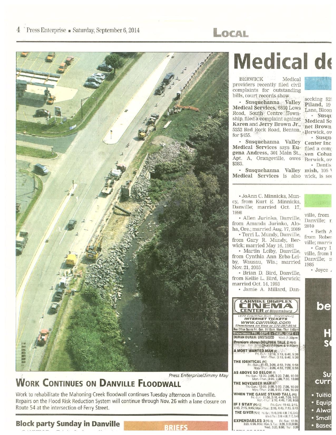
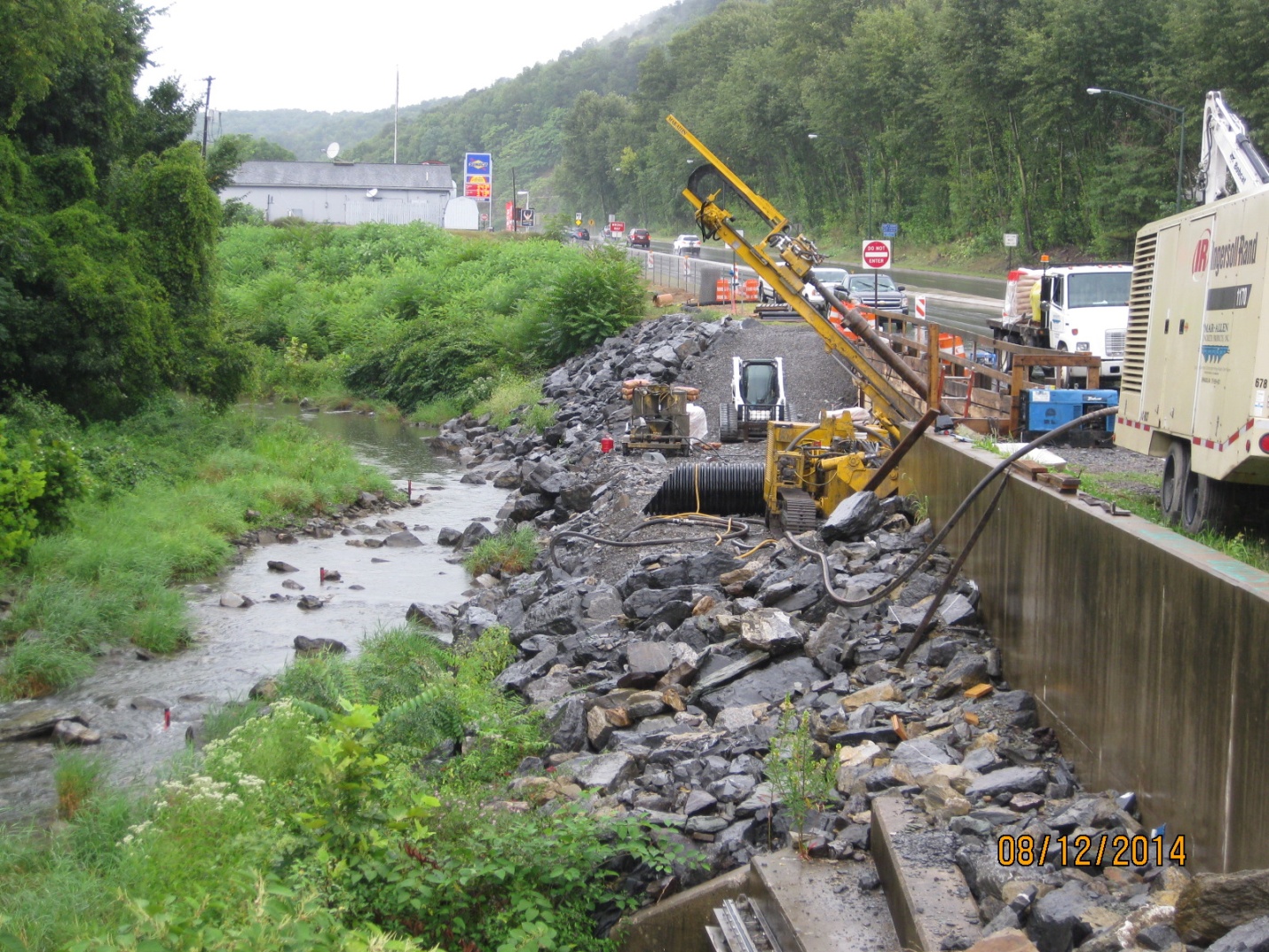
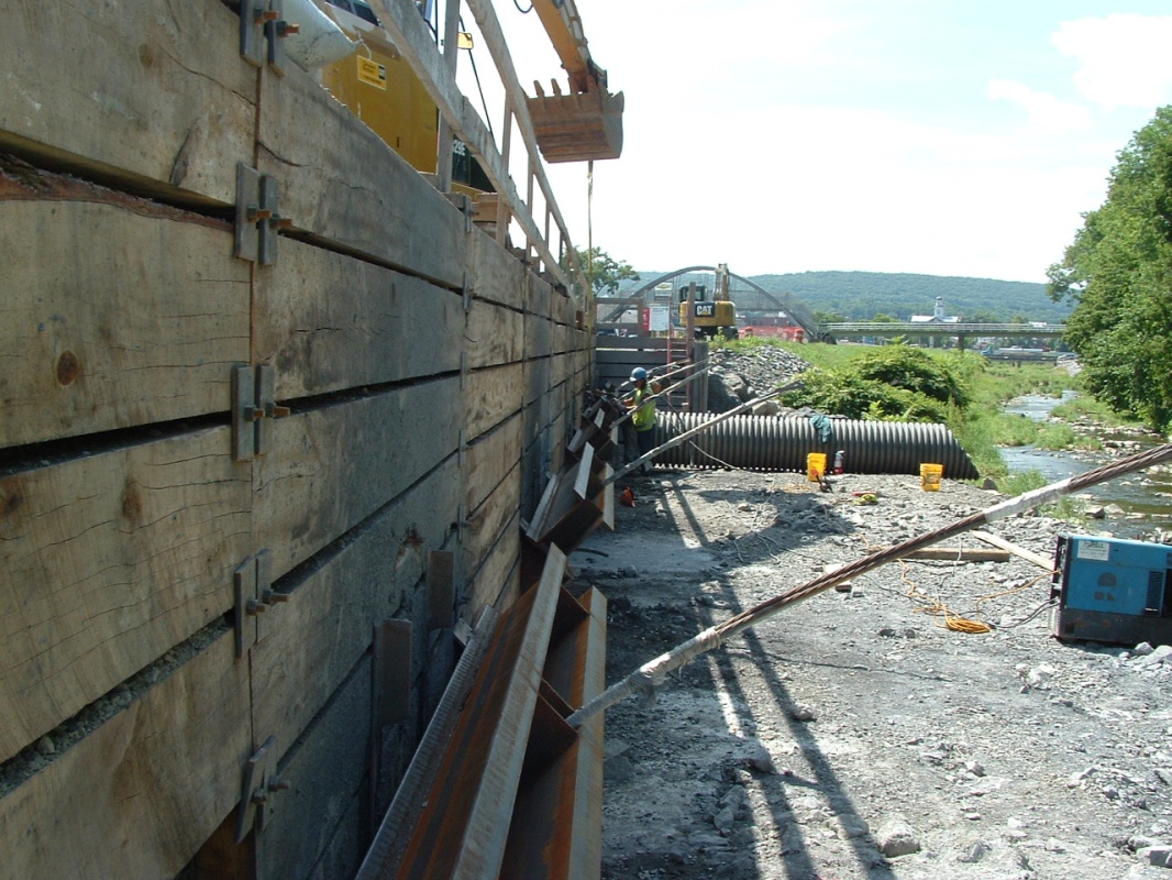
Danville can sleep safely!
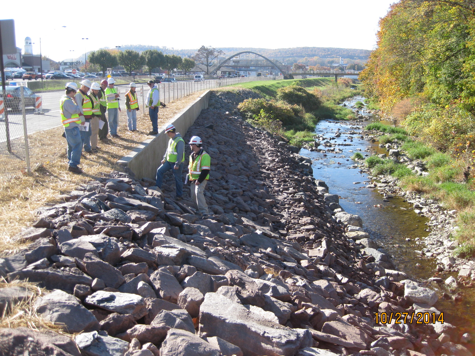
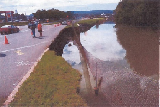
The ‘wall’ is now complete…inspected, handed over, warranties issued and snag list complete. The only outstanding issues I still have to deal with are working through the red-line drawings, chasing up failed submittals and rebutting some anticipated REAs. A good sense of accomplishment, particularly having finished a month ahead of schedule so smiles all round. Looking at it now, one could never imagine how much toil went into a relatively simple and small structure…but one that is key to saving life, and sustaining a major transport route through Pennsylvania. I compare this (on a far smaller scale) to a similar feeling probably felt by engineers involved in the Dawlish SW train track repair – a mammoth task which at the end looked pretty undramatic, but was neverthless paramount to both safety and sustaining transportation routes, tourism, economy etc etc.
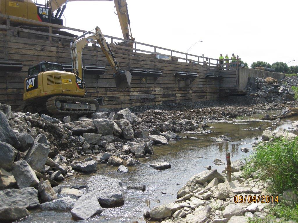
Excavation and shoring system – 2 months prior to completion
Inspection and hand-over
I have now switched the majority of my focus to the on-base warehouse project; I’ve been really impressed by the management, work ethos and professionalism of the contractor on this site – one of the advantages of the USACE posting is being able to observe and contrast management styles across different projects, but also to gain knowledge from a large pool of contractors. My focus comes at a time of large internal slab-on-grade pours incorporating underfloor heating systems; the base has suffered in previous projects from concrete curling issues so I’ve spent a lot of time digging through codes, specs, technical reports, and working closely with the QC manager to ensure that the mix design, conditions, and handling eliminates this problem…so far so good on floor flatness tests. Temps are due to drop down to 0degC next week; consequently we have been working through a cold weather plan to ensure everything continues on track – some of the research behind TMR1 has proven its worth!

The highlight of this week was the testing of rescue procedures of a man-down on the roof! Clearly the on-barracks fire brigade were warned off, because the whole wild-west turned up on-site within 2 minutes. Despite my muffled laughter of handle bar moustaches (this wasn’t Mo-vember!)and denim jackets, the serial proved valuable in testing the procedures…or lack of! Following a debrief, I essentially rewrote the entire actions-on procedure for the contractor who, to be fair, didn’t really have a starting block – for once, some practical non-engineering military knowledge brought to the fore.
How long is too long…USACE style
![IMG_3457[1] (1)](https://pewpetblog.com/wp-content/uploads/2014/10/img_34571-1.jpg)
Water, water, everywhere
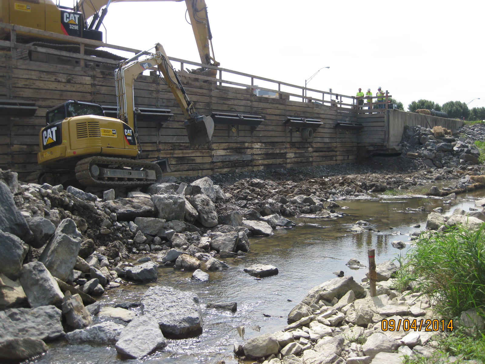
It’s been a hectic couple of weeks, with several issues occurring as we excavate further but I try to remind myself that its all great experience!!
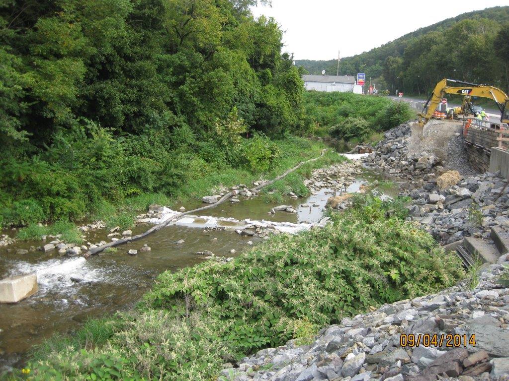
Looking north; river flowing towards the viewer. Dewatering partly in place – dammed upstream and down, with water being pumped around site.
Looking at site from across the river, supposedly mostly dewatered. Note stake in foreground shows limit of excavation for the dug-toe.
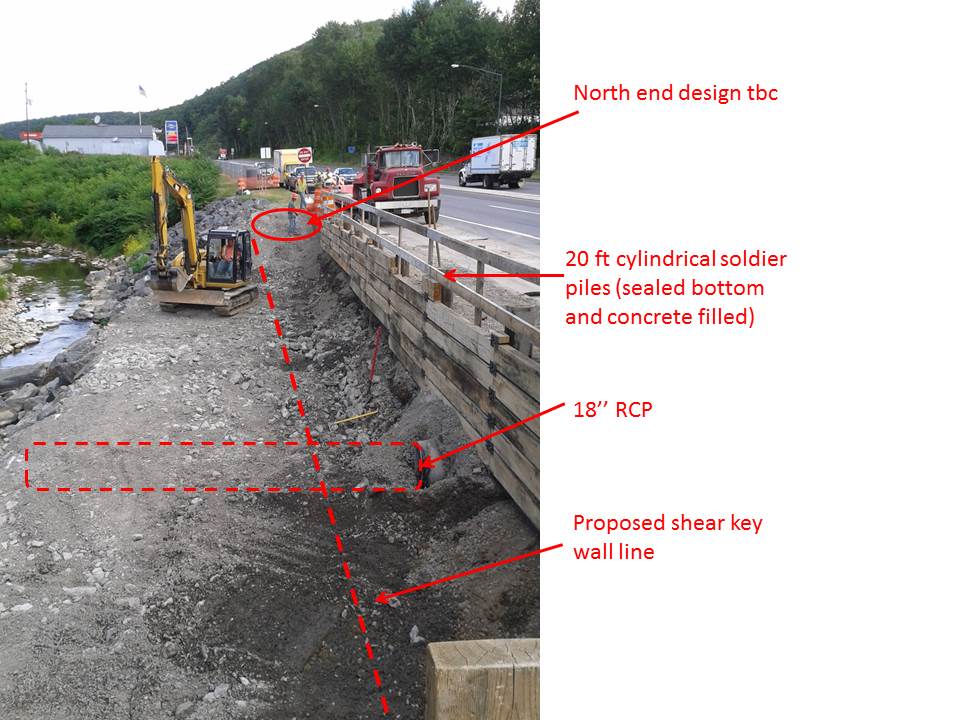
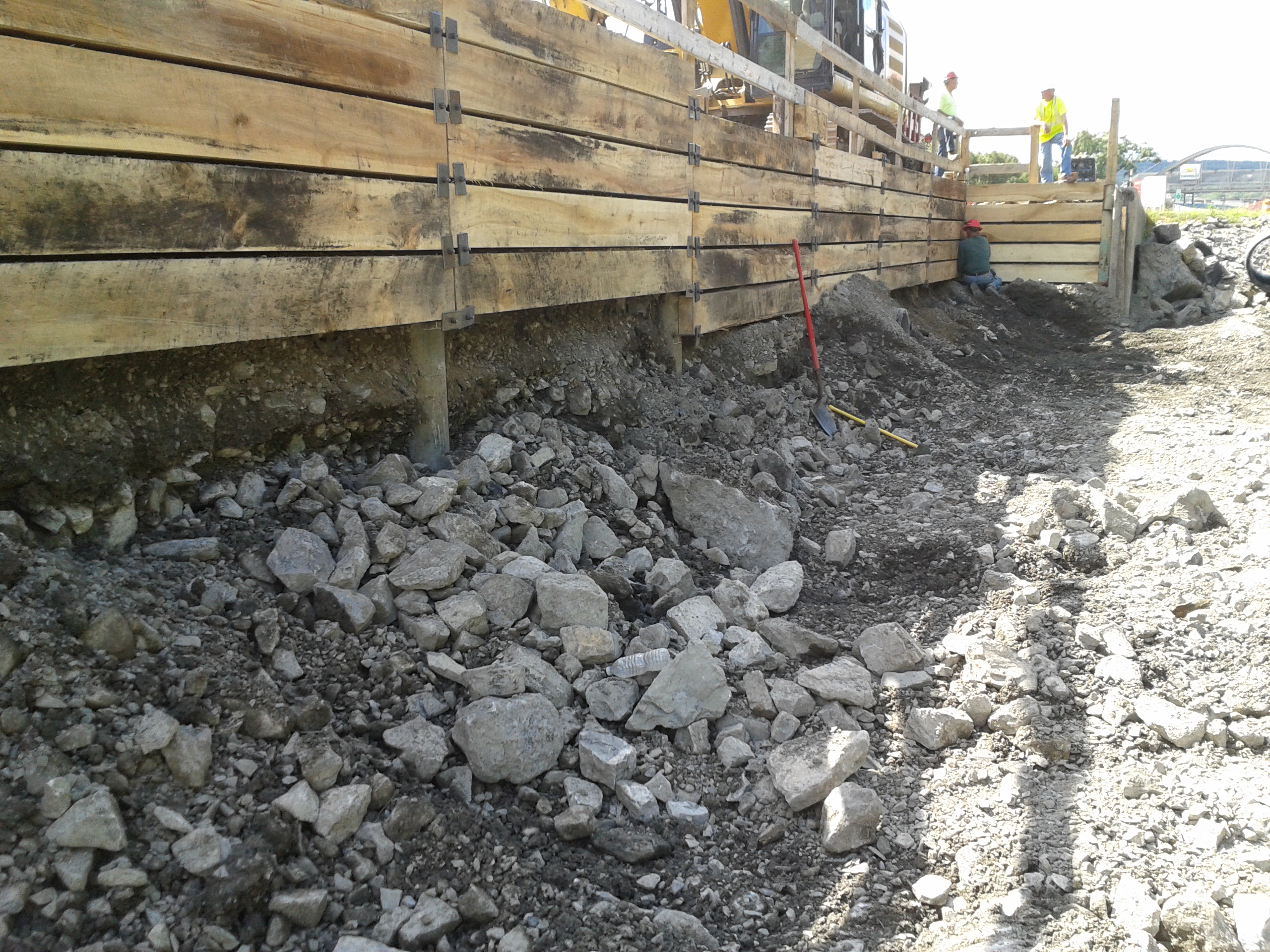
As usual, pretty much everything problematic has been a result of water! Upon reaching the limit of excavation at the base of the shoring (13ft) and reviewing submittals for the structural fill I had some major concerns:
- The excavation was starting to get wet underfoot, plus I could see (in concert with some local knowledge) that the visible river at 1-2ft deep was actually running several feet deeper and was flowing under our site following its original path under the retaining wall and the highway. This tied into the issue that was raised by the tie-back drillers that they were hitting water at 15-20ft. Annoyingly the original borehole logs down to 28ft do not show any indication of water on them – not helpful!
- The dewatering was having minimal effect; there was more pumping to occur within the two dammed walls (pic top left) but it was evident that it would be nigh on impossible to dry the area in order to excavate the ‘dug-toe’, and then lay the proposed structural fill (lean clay) and compact it to 98% of lab dry density. (Readers may see the system as somewhat Heath-Robinson but we are ham-strung by the Env Agency design manual, and the inability to have any plant in the water – it was too late in the day to design a causeway and build a by-channel, plus see notes at para 1)
- As mentioned above, the submittal for the structural fill was a low-plasticity clay – the purpose was to produce an impervious layer across the site. However, if you have a look at Sheet C-303 below you will notice that the clay extends from the base of the toe all the way up to the edge of the shoring; more concerning is that the concrete wall sits on it. How on earth is a wall going to be structurally stable sitting on clay which will continually be dried out and saturated (note the mark of ‘normal water level’ – 5ft above where it is at present)???
- The damaged wall in 3 x 30ft sections had fallen at different angles. I managed to work out what was where by measuring what was poking out, and what was embedded and at what angle. The concern was the amount still embedded below the limit of excavation, and that a huge amount of sediment was entering the river downstream of the site whenever the wall was being broken up (additional evidence that the river is flowing under the site).
- A void was visible on the south side of the site underneath the existing wall – clearly caused by erosion once the wall had fallen. Rebar was also exposed and the water joins were ripped (see pic).
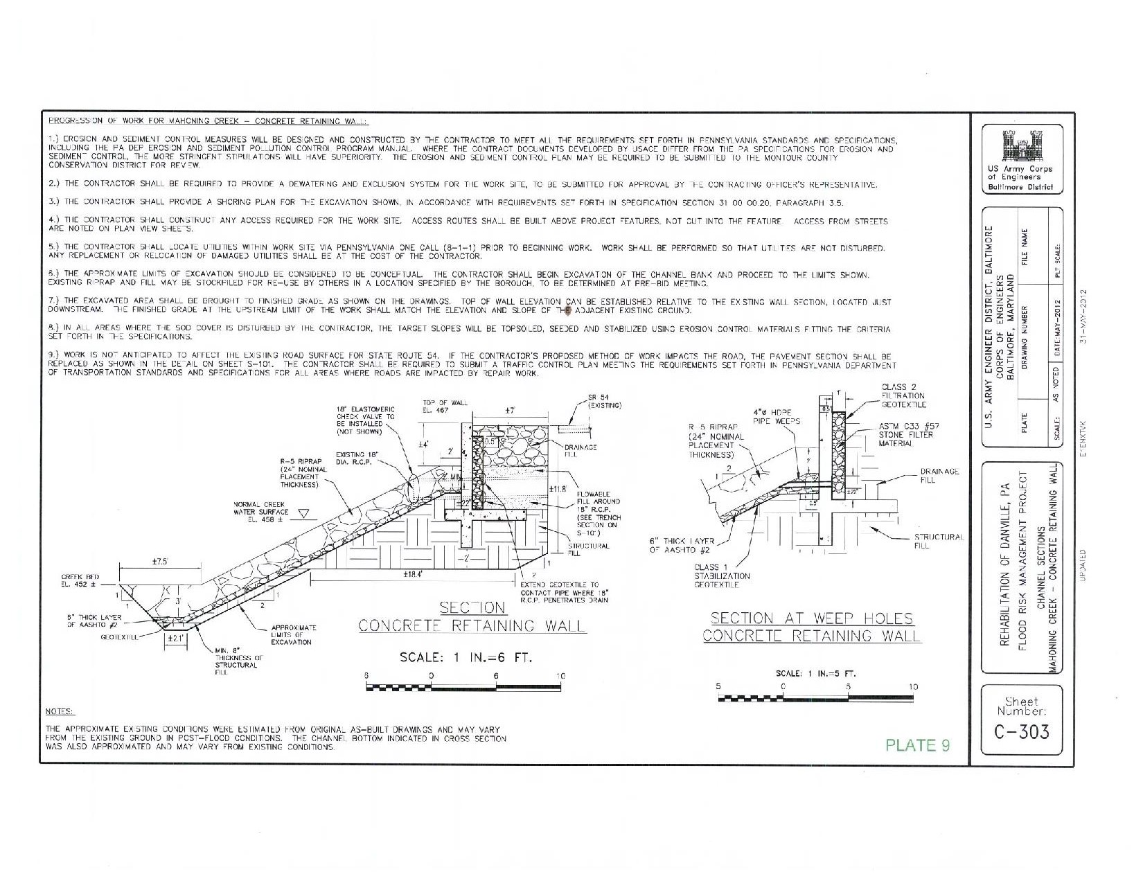
Original design
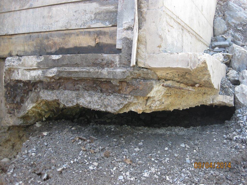
Void underneath existing wall to the south of the site
Additional limitations. Predominantly timelines…
- The Environmental Dept informed the contractor that wild trout egg stocking was to take place on 1 Oct thus the river will be in lockdown for any in-water works from 1 Oct – 23 Dec..that leaves us 3.5 weeks! Annoying that we didn’t know this as a limitation at the start (why not? I beg the question, have we got ourselves to blame?)
- The Env Dept stipulates that the dewatering scheme chosen must have a maximum lifespan of 2 weeks otherwise a new bypass system was to be designed. The contractor, without me knowing, essentially pushed himself into a corner by installing it as soon as we had approved it assuming that the E&S approval would follow shortly behind…it didn’t, it was disapproved and needed significant redesign. This put extra pressure in making any changes; some may say that is their issue/ fault – it is but we all want to get a solution in place, if we sat back, the project would fail, no funding was in place for next year and we’d be left with an open excavation, so we were all pushed into a corner somewhat!
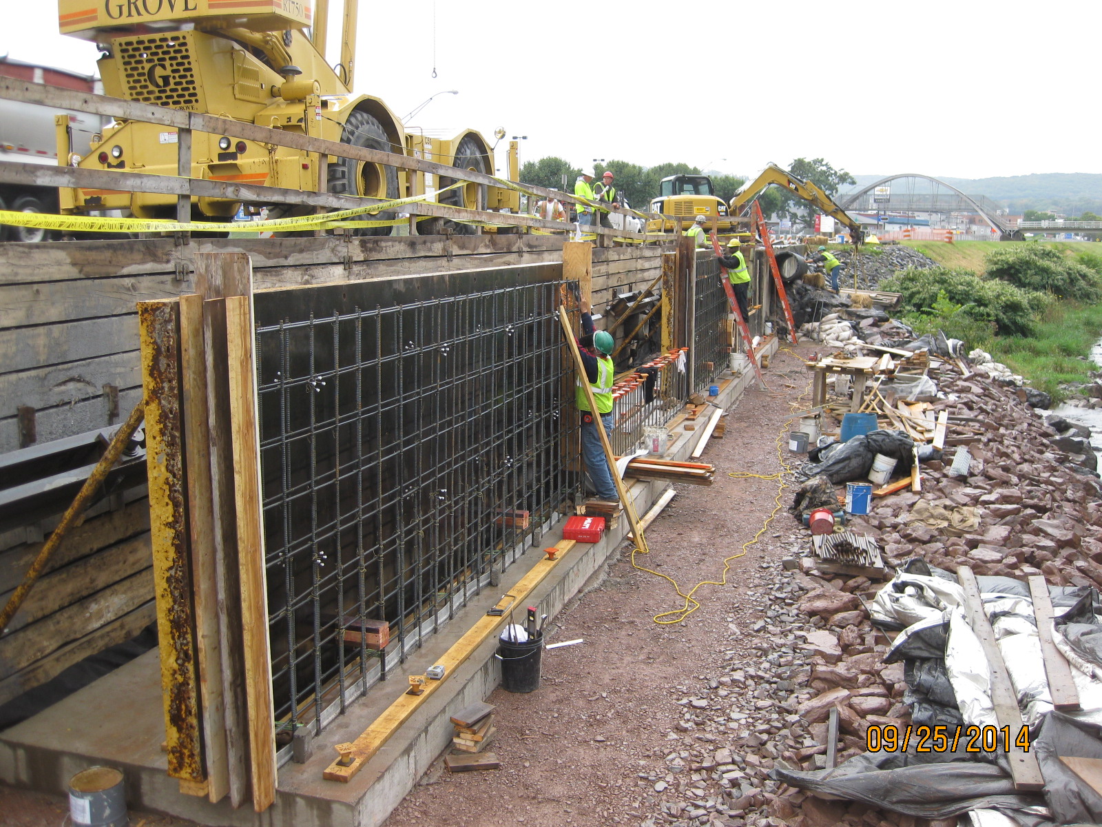
Several conference calls later and many hours of brain-racking through options with the USACE depts of geo-tech, civil works and structures we came up with a multi-faceted solution (see pic below). The embedded original wall would be left in-situ for fear of incurring additional sedimentation, plus enabling staying on track with timelines and the consensus that it may actually help in preventing scour. The dug-toe would be removed and a new design incorporating an ‘anchor stone’ and additional reinforcing rock armour would be used (see pic), while the structural fill specification would be hastily changed from clay to a coarse gravel; this would negate the need for major dewatering and speed up time of construction. We all now have to be on the ball with processing submittals asap to meet the 1 Oct 14 hardstop. This now leaves the painful part of change orders and/or REAs but needs-must.

Slope redesign
I am pleased to say that the H&S and QC has made a dramatic turn following the insertion of the 3rd party assessor by the contractor. It is clear that morale has dived a little amongst those on site following some serious whippings, but I have no doubt they will take it on the chin and move on. It is good news, and the assessor confirmed with me that things were far from where they should be! He’ll be on site until things reach my stipulated levels per USACE specs, and then a bit longer to ensure it is maintained. He even phoned the county sheriff direct raising his concern the morning I arrived on site that some drivers were driving past at 70mph in a work zone and 35mph limit. Cue a cop-car with speed gun on site within an hour and some great viewing of law enforcement US-style in action!
We also had a ‘congressional tasker’ (akin to the Complaints Commissioner writing directly to the CO!) …cue flapping all round. The ‘tasker’ stemmed from a Danville local writing to the Congressman on the back of a fag-packet his concerns that the project was a ‘waste of money’, because we are building the wall the same as was originally placed, and that the original wall collapsed as a result of scour to its rear. He was quite correct, but federal law (PL84) has tied our hands and dictates that disaster relief work on hydraulic related projects are done on an as-built basis. Several conference calls later, the attached letter was produced.

Plus, a bit of media publicity…
Also, this weekend sees the national ‘Star Spangled Banner’ celebration taking place in Baltimore’s inner harbour…100s of tall ships, Blue Angels flying displays etc – all to celebrate the 20oth year to the day from which the USA hangs its history…the first location to withstand bombardment from the Royal Navy, raising the stars and stripes for the first time, and providing the backdrop from which to write the national anthem! We will of course be attending…in a disguise of dodgy stars and stripes sunglasses and a Dunkin’ Doughnuts coffee permanently clasped in our hand; no-one will guess we’re British!? In other news, and not that we’re competing with the other HRH but maintaining the tradition of Phase 3, Emily is pregnant with our 3rd!
Safety is not a dirty word…
Safety has been the mainstay of my last couple of weeks. Whilst hierarchical eye-brows were being raised at the photos I continually produced showing a lack of grip of PPE on site by the SSHO, I did some more digging into the site safety. What was initially a little thread pull, turned into a set of pants falling down around the ankles!

Grouting about tie backs (before eye-pro!)
Following installation of the walings and allowing a week for the grout to cure, we have just completed the pull testing on the anchors at 133% of design load. On a site visit to observe the installation of the soil anchors and grouting, I was again hit by sub-contractors without eye-pro, some without high-vis, and others with no hard-hats. As mentioned in previous blogs you may have realized my frustrations at the inability of the QC manager who is double hatted as the site safety officer (SSHO) – hence my decision to ramp it up a gear as my initial hand-holding and constant on the spot rectification clearly handn’t worked. Safety clearly wasn’t in the psyche of the SSHO nor was the understanding of documentation, briefing or indoctrination. I enquired from the operators as to whether they had safety briefs upon arrival on site – the answer all round was ‘no’. Further questioning turned up no hot works permit for welding (as per USACE regs), no accessible first aid kits or knowledge of their contents, no eye wash, no material specs on hand, no accessible emergency plan with routes to hospital etc etc…it went from bad to worse. Upon my return to the office and back briefing the Area Engineer and H&S coordinator, I immediately drafted a dismissal letter to the contractor’s CEO for removal of the SSHO. Somehow the CEO later managed to calm down our Area Engineer, by the promise of a rectification plan within 72-hours and discipline of the SSHO.
The rectification plan has been pretty thorough with the additional intent of bringing a 3rd party to conduct an independent safety audit. The QC has improved dramatically, with the QC manager for the first time intently conducting 3-phase (prep, initial and final) briefings and inspections correctly and with all involved rather than on the back of a fag packet and solely him and the foreman present. I tend to find that safety goes hand in hand with the QC as I would suggest good safety is a function of sound, comprehensive QC. However, my safety ‘feelers’ remain alert so I have gone through the Accident prevention plan (APP) with a fine tooth comb as it is only the risk assessments and CoC diagrams that have been updated since the first 2 phases of the project that were completed last year. What could very well be a scene from Monty Python, was when the USACE H&S manager decided to check the emergency contact numbers in the APP, as they curiously were not 911?? The telephone answer was: ‘’Hey, this is Misty’s bar’’..once the H&S guy had picked himself up from the floor, he managed to do some further enquiry to realise that till not so long ago the bar was the manned telephone for any out of hours fire emergencies as Danville’s fire service was a volunteer service (who presumable were permanently in the bar??). It wasn’t still the case, cue more knuckle rapping. Needless to say the contractor’s rating will be rock-bottom at the end of the construction project.
So, questions I’ve been asking:
- Why did we approve this SSHO, when his CV shows no safety management experience on it other than a 30-hour online course? (Answer: there isn’t answer; we dropped a ball and let it pass under our nose a long time ago!)
- How did this contractor win this contract when it is becoming apparent that they have minimal experience working with USACE (other than a single roof job), no experience working with levee systems and it is becoming clear they are purely a management layer for gaining works and then subcontracting everything out…I also have my assumptions that the APP was written by an external party, as supposedly the SSHO on my site is the contractor’s corporate director of safety…he doesn’t even follow his own APP rules nevermind USACE’s. (Answer: this project was put out to bid amongst ‘small businesses’ – those with an annual income less than $25.5mill. Tender evaluation for such businesses are done by contracting division in Baltimore head office and the dept deals with over $1bill of projects annually…I therefore get the impression that projects such as mine are fast-tracked and minimal resources are allocated to the technical and managerial evaluation boards – I hope to explore this a bit more when in Baltimore for Phase 3)
Negotiations and change orders have now been put to bed for the north end shoring system, the damaged drainage pipe running through the middle of the site, as well as me sitting down with the sub-contractors designers to discuss new site dewatering systems – the longitudinal extent of the excavation was further out than originally thought, especially with the heightened water levels (see pink flagged pegs in river). Instead of the dike system in front of the excavation, we have planned to dam the water upstream with jersey barriers, sandbags and plastic sheeting, whilst pumping the water around the site in addition to the smaller dewatering system within the excavation area. Other options were to change the size of rock armour being used to allow for a steeper slope thus a tighter toe. A lot of our ideas are hamstrung by Public Law 84 for disaster operations, Pennsylvania’s dept of environment permitting and the timeline for which dewatering is intended to take place.
Looking south through the site; note the stakes in the river showing extent of excavation hence the need for a rethink on the dewatering plan
Excavation down to approx 10ft; wales now attached awaiting tie back performance testing.
In other news, Emily and I were kindly given tickets to a pre-season NFL games by a fellow USACE employee for last Saurday evening – what an experience…USA testosterone in all its grandeur!
Drove my Chevy to the levee, but….
the levee was dry…well not yet actually, because we still haven’t approved the dewatering plan!!
The Danville flood wall remediation is now in full swing, and is taking up all my time (not helped by the 5hr return journey to site), so my attention has switched from the HQ DLA. To be honest, it’s no bad thing as struct/civ involvement is now minimal, and I’m not getting much more from it. Instead of being a small fish in a big pond, I now have the con which is really satisfying.
I have managed to get hold of some photos of the damage caused by the Hurricane in 2011 to the wall – the raise d’etre for my remediation project…
Looking south; the washed away wall sat 1m to the right of the fence

Looking North-East once river level lowered; the area to the left of the wall is what was washed-out (30m of wall).
The list of issues we’ve had is endless; the primary headlines are as follows:
– Unforeseen ground conditions. The biggest issue to date – who would have guessed??
- The temp shoring plan was designed by Larson’s group and hinged on tie-ing into an existing sheet pile on the north end and into the existing concrete wall on the south. Of course, as luck would have it, despite us supplying drawings that showed a sheet pile, there hasn’t been one found to date. As such, the excavation on the north end has had to cease at 5ft until a solution is devised – initial discussions with the designers suggest trying to minimise cost and time by using some of their H-piles they have in their yard and slotting in timber lagging between them. Of course there will be an REA submitted by the prime for lost hours and unforeseen ground conditions (USACE has to approve any new design iot prevent Heath Robinson work…and the approval is allowed to take 30 days!). This will be heated negotiation – from our standpoint, though the drawings were wrong, we did not dictate the shoring design of tieing into the sheet pile so the risk of it being there was borne by the designer. The other issue resulting from the lack of sheetpile is how the actual wall will now end, as we had designed it to tie into the sheet pile. After much debate, we agreed that if a sheet pile was there it wouldn’t do much anyway to cope with an extreme flood event as seen in 2011. In addition, we are fully conscious that this design is extreme overkill and forced onto us by the Dept of Transport – we would have been content to leave the remedial solution of rock armour fill and be done with it. Thus the wall will end abruptly but be surrounded by rock armour.
Looking North, standing on existing wall
Looking south, excavation in 5ft lifts before lagging and welded attachments installed
- The geo-analysis and boreholes indicated the necessity for drilling through ‘rock’ (betw 8-10ft) in order to gain their sample to 22 ft. That therefore pushed the shoring design immediately away from sheet piles to the present circular tubes with welded bolts and plates and timber lagging. To date, I can count on one hand the amount of ‘rocks’ (>30cm) that have been excavated – normally parts of broken up concrete wall used as emergency fill; the remainder is 95% gravels – everyone is therefore asking the question as to what happened with the borehole samples (3 taken; 1 every 10m), especially as the shoring redesign was one fo teh main causes of several months of delay.
- The damaged concrete wall is now starting to be unearthed – we are unsure how much is there but I estimate at least an 18ft length (x 2ft width) at present. This will incur removal costs that have not been agreed upon as yet as it was guess work as to how much we would find…additional homework with answering RFPs.
- The 18inch reinf concrete pipe that runs perpendicular through the site taking runoff from the road to the river was initially decided to be dealt with by propping it up. Upon excavating down to it, it is actually damaged so has been removed and temporarily replaced with a plastic pipe. This has actually expedited site work, but we will have to pay for a new one.
– QC and safety ability of the prime. The prime has used their own guy as the QC rep and the safety offr. That is fine…if he was actually capable. Every time I have been on site there have been issues. To be fair at the moment there is not a great deal to check QC wise, so errors are pretty obvious. Annoying that I have to pick them up which results in disappointed Dad type chats…to a 50+ yr old! Somewhat aggravating as well that every question I ask, his comeback is: ”Let me ask the sub”! (the sub is essentially running the show!). Another classic was my question on D+2 – ‘where’s the E&S control’ (a pre-req for any constr); reply: ‘there isn’t any’! Needless to say that was the wrong answer; upon me going through E&S plan which he submitted to USACE I then asked where the Inlet protection was (i.e. filter bags attached to drain grillages) to which his response was: ‘What’s inlet protection?’…queue more disappointed Dad expressions, turn the page and show him the drawings!! As for safety, his inability and inaction has now become almost humorous – taking photos of welding (with welder and assistant not wearing eye pro!), workers not wearing high vis (in a heavily trafficked zone), standing right next to an area that has caved in behind the shoring and not thinking to do anything about it. Sadly, today I’ve been writing up an assasination on him upon request of the USACE area engineer who will use it as additional arsenal when chatting with the prime’s CEO and scoring their performance on the gov database. These nuggets are but just a few of his errors; he takes great photos though!
– Specs, drawings and standards…who wins? Well, of course standards do, then specs and drawings. The ‘as-built’ drawings (built in the ’70s) show joint spacings at 30ft intervals. As a result, the contractor has planned their formwork, rebar etc for such spacings under the pretense that the wall is to be built ‘as-built’ (total wall distance is 90ft). However, they have now seen that our specs say that joint spacings should be a maximum of 24ft, and the designers drawings show 20ft. Our answer to their obvious clarification RFI was that backed up by ACI and ASTM – a max of 24ft for a gravity walls. Queue – delays, rework, REAs, but again our standpoint is that construction must be done by specs unless superseded by standards – both of which coincide; we cannot be blamed or pay-out for errors resulting from using as-built drawings that were not built to today’s specs.
– Means and methods. As the government’s (client’s) representative we cannot dictate means and methods; this is quite useful at times for keeping one’s hands clean of risk, however I find it exceptionally frustrating when seeing things on site that can be expedited with a bit more planning and forethought, enabling concurrency of work. The QC manager however, though not particularly capable, is quite receptive to my ‘suggestions’ or ‘if I was to do it, then …’. A potentially major problem has however cropped up as a result of not knowing the means and methods when approving plans in piece meal. I have grave concerns that there is no sediment control on the most obvious largest issue – the excavation; thankfully the plant op is pretty handy so debris has been minimal if not nil, but all it will take is one storm and tornado and the pristine protected trout stream will become but a cloud..and the Dept of Environment will be throwing down a rather hefty fine…on the contractor mind, not us. Just because we approved the drawings does not absolve the contractor of responsibility or risk; our rational for approval was that the dewatering diversion dyke would also act as a sedimentation barrier hence we approved it…the diversion dyke is part of the dewatering plan which still hasn’t been approved yet for a variety of fairly minor issues, and has been held up by the QC manager for a week having mislaid its location in the approval chain on the bespoke USACE IT system that we use for communicating drawings, specs, RFI, REAs, submittals, payments etc.
In other news, the family headed out on a long weekend roadtrip through Pennsylvania into New York state, stopping off for one night at Finger Lakes renown for its countless wineries, then up to Niagara Falls – amazing experience, and well worth the miles! 

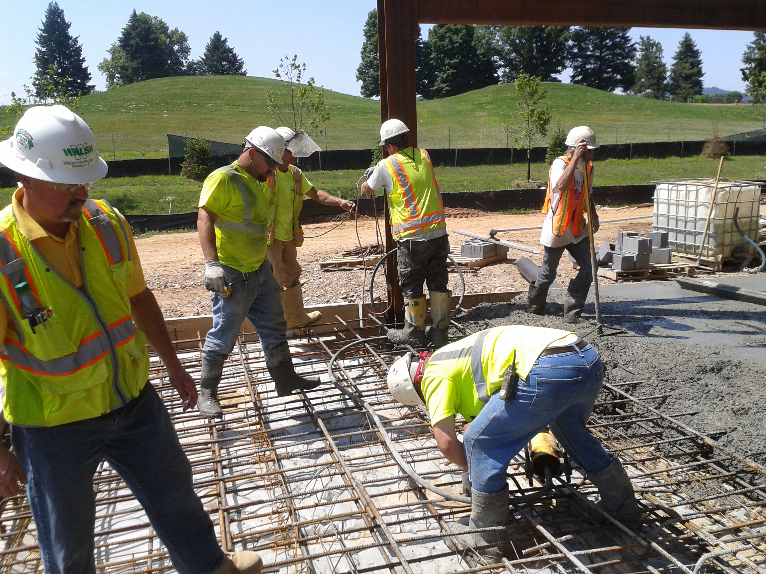
When QC falls down
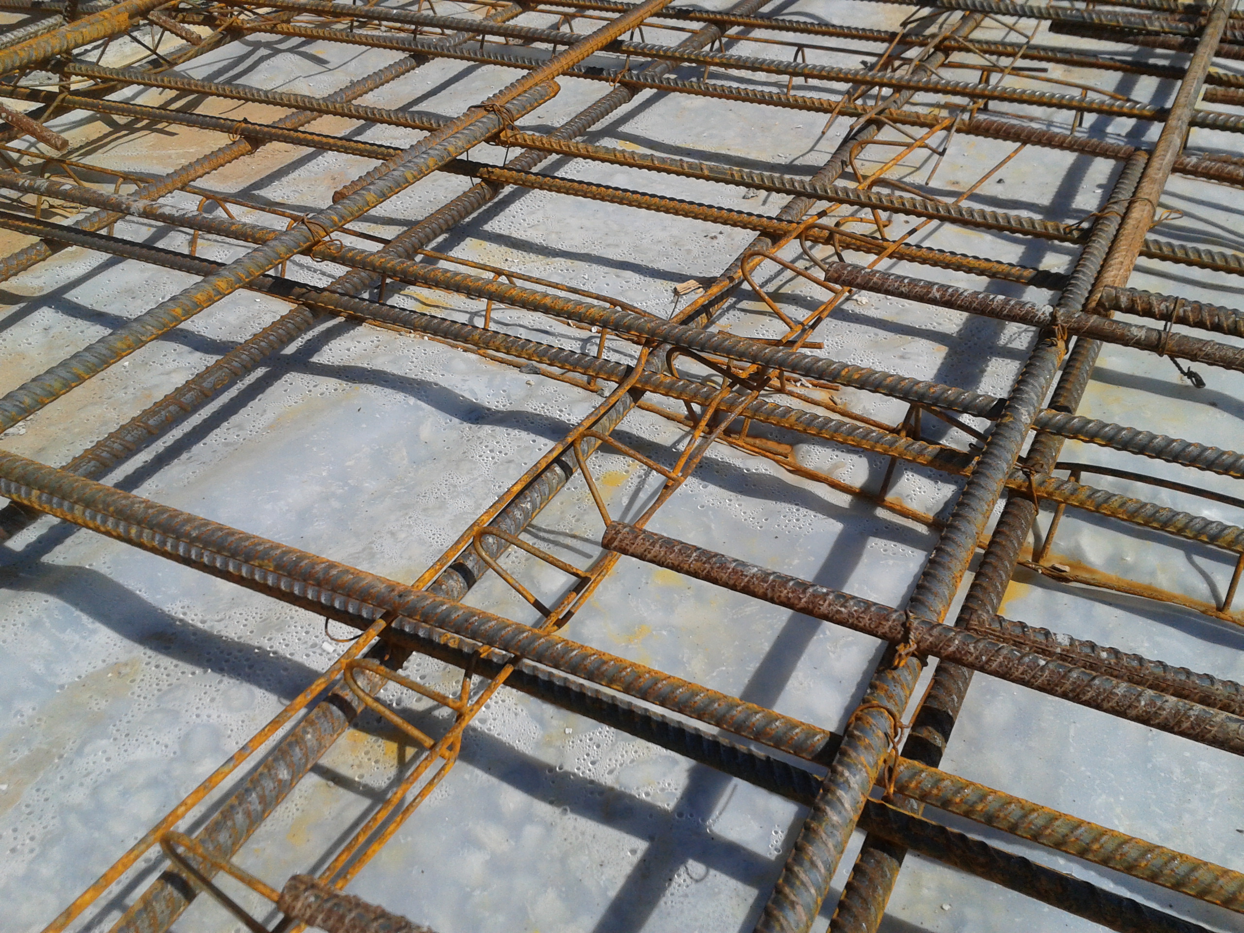
The final pour of the HQ’s Area F for slab on grade happened today…actually it was supposed to be tomorrow! The concrete subcontractors took it upon themselves to pour the slab – in my view so that they could rush off site finally and start another project down south. I’m yet to get to the bottom of what exactly happened, but as I was about to start to look over the rebar I found the concrete pump vehicle parking up next to me and the concrete crew moving to my area from their last slab pour. Having not seen anyone, I presumed all must have been in place with regards to checks and that maybe I had just missed a beat. Nevertheless, I continued to check over the steel as the pour started and started to find problem after problem. What then ensued was one of those awkward situtions where the USACE QA guy with the funny accent had to step in and stop 10 grizzly concretors and cause a back up of several concrete trucks. Clearly the commotion and grumbling resulted in the QC manager and various Walsh engineers rushing out to see what was going on. It then turned into a mess of fresh concrete being dug out, formwork being replaced, and concretors swearing at each other trying to rectify errors I kept raising – Joe, I can sympathise! Problems, to name but a few, were as simple as:
1. Top rebar not being tied down.
2. Top and bottom rebar having clearance from formwork as little as 1cm (should be 2” = 5cm)
3. Laps not being tied together.
4. Rebar seats having been crushed causing a spacing of, at worse, 2cm between top and bottom rebar (slab thickness – 25cm)
Thoughts….
– Only one external QC guy is employed to QC all concrete, cementitious material and rebar across the whole site. He believed the pour was happening tomorrow and intended to check the rebar this morning with me; this meant that when the concrete trucks turned up, he couldn’t check over the steel and was pulled away to do slump checks on the incoming concrete. To add to his confusion he was trying to QC the grout being used for masonry. It is clear to see that QC is starting to slip off the agenda as contractors rush to make up time, and QC is not a deciding factor when scheduling works that overlap – IT SHOULD BE! QC employment and scheduling needs to be thought through cleverly – many a day he has nothing to do, and is there purely because contractually he has to be. This is crazy and I feel his presence is starting to become a box ticking exercise!
– I read an interesting article about ‘QC and continuous education: providing tools for contractors to make ethical decisions’ – BLUF how HR depts need to employ QC workers by personality type, by using tests such as Myers-Briggs in the interview phase, to ensure that QC workers are capable of making ethical decisions. Today was case in point – Walsh’s QC manager told me he had walked the rebar this morning (he was clearly aware that the pour was happening); that was before I then showed him the errors. Hoping he would then rectify the problemsand relieve me by directing the concrete sub-contrators, he limply tried to stop the concretors pouring concrete but then just shrugged his shoulders when they couldn’t hear him…I then had to wade in again. In addition, the external QC checker should have had the balls to raise the issue straight away to the QC manager; if I hadn’t have turned up, the pour would have just carried on!
Never a dull day…
