Archive
Bridge Design Using Microstran
Phase 3 has been useful in drawing on my experiences from Phase 2 to apply to the design of bridges, in particular their foundations, and large diameter piles.
John Holland have employed me as design coordinator which has allowed me to design parts of a 261m access bridge to a rail stock maintenance facility inconjunction with the structural consultant, BG&E. The curved bridge has 8 spans, with 2 x 4.0m lanes and 2 x 0.5m shoulders. The girders are 1525mm deep PSC super T’s supporting a 200mm cast in-situ continuous deck. Each super T is supported by an elastomeric bearing. The piers are supported on one single 2100mm dia driven steel tube, bored to the point of negligible bending moment.
The set out of the bridge was completed in AutoCad by the architect, Arcitectus. I then exported the .dwg file to a .dxf file to import into the structural software, Microstran Advanced V9. I then added nodes, line properties and interactions to build up a 3D structural model of the bridge (Figure 1). 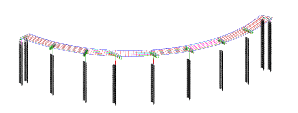
Figure 1 – Idealised Microstran 3D model of structure
The deck-super T connection is rigid, allowing loads to be laterally redistributed between super T’s longitudinally and transversely. The load transfer and redistribution depends on the stiffness of both structural elements and the supporting ground. Longitudinally the structure ‘floats’ on elastomeric bearings, longitudinal loads are shared between piers due to the bearing shear stiffness of the elastomeric bearings. The connection between the super T and headstock is modelled as a line with equivalent stiffness as the elastomeric bearings stiffness. This approach correctly models the interaction between superstructure and substructure of the bridge. The deck is restrained laterally by restraint blocks transferring load into the piers and abutments. HDPE plates are provided between the restraint block and girder to prevent concrete bearing on concrete. Load sharing affects the design of piers, piles, bearings and movement joints.
With guidance from BG&E, I was able to create a deck grillage model with appropriate longitudinal and transverse stiffness’s for the deck slab and girders to determine the design actions due to variable loads in the superstructure and substructure. Load cases were assigned to the bridge as per AS 5100; Permanent; Super imposed permanent; Footpath; Breaking; Centrifugal; Collision; Pedestrian; Shrinkage; and Creep. This model has been used to determine the design actions due to gravity and horizontal loads in the substructure. I then passed these values to the geotechnical engineer, SMEC, for pile design and expected settlement.
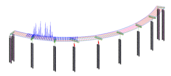
Figure 2 – Load model
Serviceability Limit State
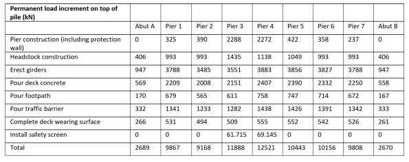
Serviceability deflections are critical for construction. During construction the loads on the piles progressively increase. I have broken down these loads so that the geotechnical engineer can calculate the settlement at each stage of construction. The bearings under the girders are set to levels by the use of a cementitious grout pad below the bearing, these can be adjusted to give the final surface level within serviceability limits.
Table 1 – Permanent load increments on top of each pile during construction stages
Lateral Soil Springs
The structural model needs to be supported, pinned or fixed supports are not realistic, soil springs are used to represent the pile-soil interaction and are applied along the length of the piles. The springs stiffness represents the lateral stiffness of the soil in that location modelling the pile-soil interaction. The behaviour of springs is predictable to understand and can be incorporated into Microstran.
As soil behaviour is nonlinear spring stiffness depends on geometry and load. The relationship between the structural and geotechnical engineer is therefore iterative. Structural engineers require a spring constant, but the modulus of subgrade reaction is highly variable with geometry and load. Geotechnical engineers require deflections under known loads and geometry. This though depends on the foundation stiffness. I have been managing the channels of communication between the structural and geotechnical engineer.
Checks are required as to whether soil passive limits are reached. If so, this is where deflection is greatest at the top of the pile, and the affected springs are removed and replaced with a force equal to the passive limit.

Figure 3 – Inputting spring constants provided by the geotechnical engineer into Microstran
Inadequate Toe Bearing in Permanent Cased Bored Piles
Since June 2016, one of my tasks has been to track progress for the solution to the bearing capacity issue faced on the Rail Bridge cast-in-situ permanent cased bored piles. The testing methodologies to find a solution have given me experience in a full repertoire of sequential testing procedures. Bit of a lengthy blog but gives a good insight into pile testing. I would be interested to see whether you would take the side of the sub-contractor or the client?
Background
The new Rail Bridge through the Airport East site is supported by 6 large diameter permanent cased piles, P1 and P2 are 1200mm dia supporting Abutment A, P5 and P6 are 1200mm dia supporting Abutment B and P3 and P4 are 2500mm dia at the central pier, refer Figure 1 below. All the piles are designed in toe bearing alone and have 500mm rock sockets within Class IV sandstone.
The SLS design axial load for the abutment piles is 7.4 MN. For analyses of high-strain dynamic tests, this value was increased to 9.0 MN to account for potential future negative skin friction on the piles. The ULS design axial load for the abutment piles is 10 MN. With a geotechnical strength reduction factor of 0.52 applied, a design ultimate geotechnical strength of 19.2 MN is required (= 10 MN / 0.52).

Figure 1 – Plan view of Rail Bridge pile layout
Concerns over the fractured sandstone allowing groundwater to seep into the piles required a wet tremie pour to be adopted. Following the completion of steel casing installation (Figure 2) and following excavation, water was pumped into the casing up to the water table level to maintain positive head prior to the concrete pour. The positive head aimed to reduce the in flow of sediment from ground water flow.

Figure 2 – Permanent casing being driven during an airport possession, note the railway line has been slewed to allow for works.
Sonic logging tubes were attached to the reinforcement cages, these were kept 200mm off the base of the reinforcement cage, 300mm from the toe of the pile.
During installation of P3 and P4, the 2500mm dia piles, the 16mm thick permanent casing buckled, resulting in a bespoke reinforcement cage being required.
Prior to the concrete pours the reinforcement cage was removed from the hole to allow the base to be cleaned. The piling rig using a cleaning bucket removed any loose material at the pile base. This also agitated any sediment causing it to go into suspension prior to the pour.
The tremie was lowered below the water line to the base of the pile. As the level of the concrete in the pile increased the tremie pipe was withdrawn in sections ensuring that a minimum immersion of 2-3m of the tremie pipe remained in the concrete at all times.
Pile Testing
Cross-hole sonic logging (CSL) was used to assess the integrity of the piles. A primary advantage of CSL is that it can assess the integrity of piles at depths which may be beyond the capabilities of sonic echo testing. It is probable that a large number of piles will include defects of some sort. The important consideration is that these defects will not materially affect the structural performance of the pile. The CSL assessment detected 15 issues of ‘Poor/Defect’ anomalies at a depth of approximately 35.6m – 36.1m below the top of concrete in P2 and 4 issues of ‘Poor/Defect’ anomalies at a depth of approximately 35.6m – 35.7m within P6. Further tomography assessment of P6 at 35.7m concluded that only 40% of the cross-sectional area of the pile comprised of 40 MPa concrete.
Core drilling of the piles was then recommended. On attempting to drill and core P5 the subcontractor made 4 attempts to reach the bottom of the pile without success using a percussion drill with a 100 mm diameter tungsten carbide head. The helical reinforcement was damaged during these attempts as it was struck by the carbide head. It is assessed the drill head maybe wandering during drilling due to potentially softer section of concrete due to removal and reentry of the tremie tube. P2 was successfully cored, the sample revealed what appears to be a 50mm layer of loose coarse aggregate from the segregation of concrete at the toe between sound concrete and the sandstone rock socket.

Figure 3 – Coring samples from P2. Note the aggregate in Core 3.
The toe of the core was cleaned using air to show the extent of the void. The void was measured at 400 mm at the base of the pile and a photo is shown in Figure 4 from a CCTV recording of the core. The coring holes and toe void were grouted, and subsequent CSL showed some improvement.

Figure 4 – CCTV photo shows the void at the base of P2, slowly filling with ground water.
P1, P2 and P5 were high-strain dynamically tested using a pile driving analyser (PDA) to check the mobilised capacity. The mobilised capacity of P1, P2 & P5 exceeded the required capacity. A guide to structural integrity and performance of the pile is given by considering the energy of the hammer blow delivered to the pile by the 20 tonne drop weight (Figure 5). The piles subsequent responding mobilisation capacity and estimated static deflection at mobilised capacity was much less than the allowed movement of 85 mm. The temporary compression of the piles under dynamic loading ranged from 8.1 mm to 9.9 mm with a 1 mm set.

Figure 5 – High-strain dynamic testing hammer on P1.
The pile resistance is subject to input data, primarily including Young’s Modulus and the Damping Constant. Corrected values of Young’s Modulus are correlated with signal matching from CAPWAP (Case Pile Wave Analysis Program) testing which estimates the total bearing capacity of the pile. The CAPWAP results showed the concrete over the length of the socket is a lower modulus than the upper concrete in the pile.
CAPWAP results showed a reduction in the axial stiffness at the base of the pile (i.e. the material at the base of the pile has a stiffness lower than that of “good” concrete). Also a reduction in the pile cross-section at the base of the pile (i.e. there are zones of contaminated or “poor” concrete at the base of the pile).
The Client – Roads and Maritime Services Conclusion
‘Whilst the dynamic analysis provides a pile capacity at this point in time, the uncertainty of the size of the voids and / or quantum of the integrity issues, coupled with the poor integrity section not being fully contained within the sandstone rock socket or the steel pile casing, results in the Principal being unable to determine the extent of any future pile settlement over the design life of the structure.’
Conclusions & Recommendations
The pile should only be considered defective if it does not meet the SLS or ULS requirements. The client has rejected the piles due to the defects with in them despite them still passing the relevant criteria. They have decide to replace P1, P2, P5 & P6, this time using a dry tremie pour, by achieving a seal between the permanent casing and the rock socket.
The reason for failure of concrete in the toe of the rock socket has not been fully concluded. After gaining a better level of technical knowledge on the subject by reading Tomlinson & Woodward, Pile Design and Construction Practise, 5th Ed, Section 3.4.8 discusses the issues related with groundwater in pile boreholes. It mentions, ‘a strong ground water flow can wash away concrete completely’. In cases of strong inflow, ‘the water must be allowed to rise to its normal rest level and topped up to at least 1.0 m above this level to stabilise the pile base.’ It does directly mention this with cased piles but, honeycombing of concrete could certainly be an issue.

Figure 6 – Example of a defective shaft of a bored pile caused by cement being washed out of unset concrete (Tomlinson & Woodward, 1977)
Despite the piles having permanent casings, ground water flow through fissures in the sandstone could have caused the grout to wash out of the concrete, leaving the aggregate in the base of the piles. Grout leakage could have occurred in the tremie pipe during delivery leaving insufficient grout to bond the aggregate. The tremie pipe may have been too far from the toe of pile on concrete delivery causing separation of concrete on delivery.
A dry tremie pour with a high artesian head in the sandstone through fissures could cause the same issues to occur. John Holland have now mitigated risk by the client providing both a methodology and load values required in the piles, with the sub-contractor paying for reworks.
Photo for Comments Section
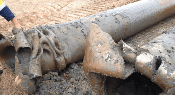
Figure 7 – Plastic deformation of a pile casing driven past refusal
Over-Flighting Causing Potential Failure of a Piling Platform
A cofferdam is required for the construction of an Underpass structure beneath a new Rail Bridge. The current rail line has been slewed 5m to the east of the piling platform to allow for the rail bridge piles and sheets for the cofferdam to be installed. The piling pad is at RL +8.0m, made of 800mm compacted DGB. RL 7.2m to RL -7.5m is dense to medium dense sand. Below RL -7.5m is clay. The GWT fluctuates between RL 1.5 to 3.5m, recharged by rainfall.
Difficult sheet pile driving conditions through coarse grained dense sand have meant pre-augering has been used to loosen the sand prior to driving 18m sheet piles for the Underpass cofferdam. A phenomenon from CFA piling has occurred on the rail bridge piling platform where the predrilling auger has over-rotated and excessive sand has been removed, known as over-flighting. In total, there are 29 augered predilling holes in the platform. the total volume of sand removed is 60m³. Therefore on average 2m³ is removed from each hole. Over-flighting of the auger is increasing the voids ratio within the ground leading to the ground around the auger to settle through vibration as the sheet pile is driven and an increased stress applied. Damian Warren experienced a similar issue at his project near the Thames in London.


Figure 1 – Tension Cracks in the Piling Platform due to Settlement from Over-Flighting
Where a coarse grained loose material overlays a stiff fine grained material issues in augering can occur. The stiff clay layer found at depth requires greater rotation of the auger due to its stiffness. The greater rotations of the auger cause loose sands in the upper horizons to be transported up the flights leading to sands around the auger to fall into the flights creating a void. The voids are being created under the sheet piling machines which may undermine their stability. An augering machine with low torque will require a higher number of rotations to penetrate the stiffer, cohesive clay layers. This issue was not encountered while drilling the CFA piles for a previous task I conducted on the site as the piles for the Canal Bridge did not reach the cohesive clay layer.
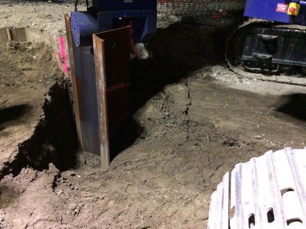
Figure 2 – Settlement of the Ground around the Sheet Pile
The stress history of the soil has been changed by the predrilling. The soil is exhibiting large volume changes after predrilling and during sheet piling suggesting it now has low stiffness compared to the surrounding strata. The stiffness of a soil is very difficult to assess. The differential settlement for across the pad could become an issue for the rigs stability and potentially effect the rail line.
The water table around the piling platform is recharge via infiltration of rain water. Heavy rain over the past few days will have caused the ground water table to rise. A high ground water table exacerbates over-fighting as the soil has increased fluidity in the weak submerged soil particles allowing it flow easier.
The predrilling is being conducted as if it were a secant piled wall, with overlapping bores. The cumulative effect of the close spacing of drilling will increase the settlement issue.
Recommendations
To rectify the issue, geogrid or cement stabilised sand could have been used to reduce excessive ground movement.
Steel plates have already been utilised to support the 72T piling rigs during driving due to settlement issues on the piling platform.
Drill rig selections should be accessed in further piling works to ensure a drilling rig is selected with sufficent torque and crowd combinations that are compatible with auger rotation and penetration into the ground.
Verification
After inspecting the piling platform myself, I wrote a report to the John Holland SPE on my findings. Subsequently a geotechnical engineer came out an observed the piling platform and concluded that the platform still met the design requirements so no further works are required. A rail inspector has also checked the alignment of the railway line, with no issues found.
Are there further issues which should be considered or is this issue normal on site?
Cofferdam Dewatering Assistance Required
Civil friends, I would appreciate your input on the following dewatering issue I am currently faced with. This to ensure I am on the right path before I look into a suitable well point dewatering system, effects of drawdown, settlement and dealing with contaminates in the groundwater etc.
Design
Sheet piles have been installed as temporary works to a set depth to form a single skinned cofferdam. A rail bridge will be subsequently constructed over the sheet piles footprint, prior to the cofferdams excavation to create an underpass. To date the sheet piles have been installed but there is no set solution to dewater during excavation.
The rail bridge is at 8.5 mAHD, the sheet piles have been driven to a depth of -3.5 mAHD (12m long). To establish acceptable dry conditions for work, it has been proposed to dewater to 1.5 mAHD (the finished underpass road level is above the water table).

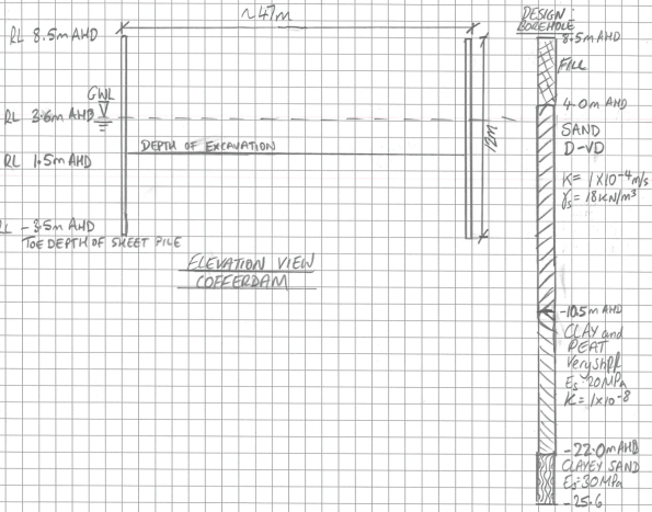
Conceptual Model of Groundwater Flow
There are two main groundwater systems beneath the site, a deeper confined groundwater system separated by the fractured Hawkesbury Sandstone and a shallow, unconfined / semi confined system within the Botany Sands. I have taken the groundwater level as RL 3.6 mAHD based on advice from Douglas Partners. Recharge of the Botany Sands Aquifer occurs through direct rainfall infiltration in the highly permeable sands as well as high and low tide. I have taken the average permeability across the Botany Sands as 1 x 10⁻⁴ m/s as per Douglas and Partners advice.
Estimation of Total Flowrate
I have used analytical methods to estimate the flow into the cofferdam which has produced a rather high daily flow rates of 1.9Ml per day.
Below is a draft flownet for the problem.

It has been deemed unfeasible to drive sheet piles to the clayey sand layer which may or may not be there or provide a cutoff.
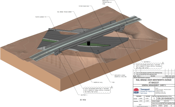
Completed Rail Bridge and Underpass structure
Many thanks.
AHD – Australian Height Datum
Blast Analysis in the Urban Environment Lecture
Blast Analysis in the Urban Environment
The Institution of Structural Engineers is running a series of lectures, this one I think is particularly interesting, it is the penultimate one in the series.
| Date | 27 September 2017 |
| Time | 17:30 for 18:00 start |
| Venue | The Institution of Structural Engineers, 47-58 Bastwick Street, London, EC1V 3PS, UK |
| Speaker | Nick Misselbrook – Associate Principal and Office Director, Thornton Tomasetti Defence Ltd. |
Description
Protective building design requires a detailed understanding of blast loads and explosion damage mechanics. Many of the tools available for blast analysis are based upon a combination of empirical data, analytical approximations and scaling rules, which are not always accurate for explosive events in complex urban environments.This lecture will give an overview of the blast analysis tools currently available, demonstrating where and when such tools are valid, and a look at state of the art possibilities.
Speaker
Nick Misselbrook is an Associate Principal and Office Director for Thornton Tomasetti Defence Ltd. Nick has an MSc in Weapons Effects on Structures from the Royal Military College of Science, is a Chartered Engineering and Chartered Physicist and a Member of the Register of Security Engineers and Specialists.
The lecture is free and you can register at the link below.
There is also a webinar and database of previous lectures from the series.
https://www.istructe.org/techlecseries
The final lecture is on the 5 October – ‘The success and potential failure of engineering computational design’. Details can be found at the above links.
Planes, Trains & Automobiles
The Airport East project has displayed the importance of management of stakeholder relations to ensure the smooth running of a site.
Roads and Maritime Services (RMS), Australian Rail Track Corporation (ARTC) & Sydney Airport Corporation Limited (SACL), are the three biggest stakeholders on the Airport East site and known affectionately as the three amigos. The contract is construct only and a number of clarifications are submitted to RMS daily, which in turn do lead sometimes compensation claims. SACL own the land but also impose tight restriction on operations due to the proximity of the E-W runway. ARTC operate the main freight line which runs to Port Botany which dissects the site and is also being upgraded as part of the project to dual lines, they also impose tight restriction and limit access to the rail corridor.
During installation of reinforcement for Span 1 of the Canal Bridge, RMS were still changing their minds right up to 3 hours before the pour of where they wanted to locate conduits for traffic lights and lighting for the bridge. Retrospectively fitting conduits into slab reinforcement is a time consuming process. This is a lesson I will be taking forward for when the ducts are fitted into the Rail Bridge for post tensioning. It is key reinforcement is staged with conduits or ducts being fitted prior to the B layer of reinforcement being placed.

Figure 1 – Conduits for traffic control systems run through the cast-in-situ bridge deck of Span 1 of the Canal Bridge
One of the most exciting yet exhausting tasks I have been package manager for on site has been the installation of sixty precast pretensioned bridge beams for Span 2 of the Canal Bridge. I have taken this process from competitive tender, standard subcontract and award, through to installation. The tasks leading up to their installation involved; authoring the activity method statement, excavation and removal of the temporary piling platform in the canal, checks to stressing calculations for the bridge beams, quality inspections of the prestressing yard, application to SACL for a week long closure of the E-W runway for 220T telescopic crane, design and validation of the crane platform, oversized load permit for delivery to site of the beams, organisation of haulage, medium risk lift plan for installation, and being lead engineer co-ordinating the landing of each beam onto temporary bearings. Choreographing their installation over 4 days, involved 15 being delivered per day, a truly rewarding task once they were all secured in place.
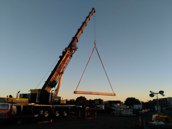
Figure 2 – The one of sixty precast bridge beams is lifted into position for Span 2 of the Canal Bridge
During installation I received a telephone call from SACL, the wind had picked up so for safety reason they needed to reopen the E-W runway. 15 minutes after the crane was lowered, the photo in Figure 3 was taken as an A380 passes over the site, showing the reason for the imposed height restrictions. This delay forced installation operations to cease until that evening when the Airport closed between 2300 – 0455hrs.
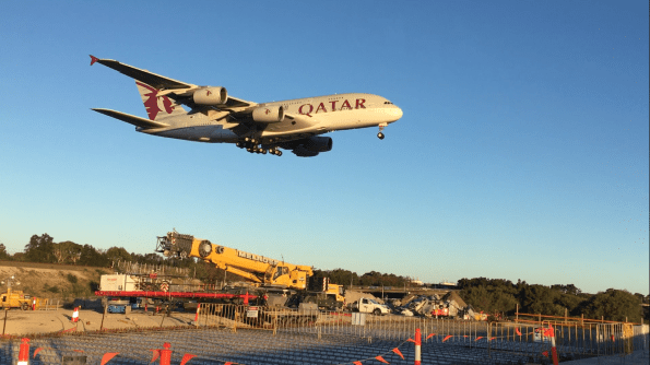 Figure 3 – SACL reopen the E-W runway of Sydney Airport during installation of the beams forcing installation operations to be postponed to the night.
My relationship with ARTC will grow as I move onto Project Engineer for the Rail Bridge and Underpass this month.
Stabilising Continuous Flight Auger Pile Excavations with Compressed Air
A commonly used piling method in Australia is continuous flight augering, with an experienced operator it can be relatively simple to install, cost effective, with limited noise and vibration.
The interesting aspect of CFA piling by AVO is their use of compressed air to stabilise the excavation. Avo use a Bauer BG 24 rig, which has the ability to inject compressed air from the tip of the auger. Compressed air is injected near the discharge pump at 150kPa increasing by 100kPa for every 10m of depth. The pressure helps maintain the stability of the excavation prior to concrete being introduced through the stem of the auger.
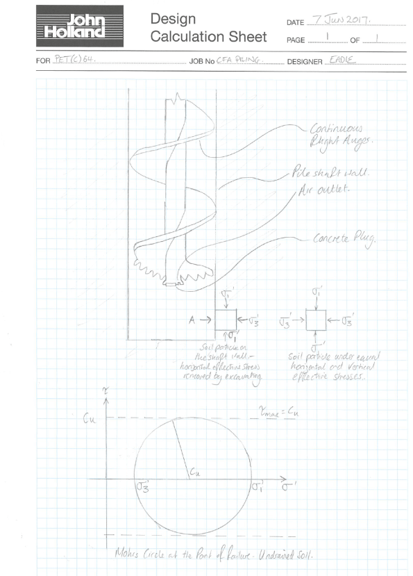
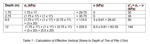
As the soil is excavated from the pile shaft, the horizontal effective stress (σ’3) on a soil particle on the shaft wall reduces to zero. The air pressure applies an equalising horizontal force to the walls of the excavation of about 250kPa, this is larger than the 146kPa which is being exerted by the soil around the shaft near the toe (see table 1). The air pressure helps stabilise the excavation from collapsing by applying a passive force against the active force from the soil around the shaft walls. Excess pressure is forced up the shaft helping lift soil up the flights of the auger.
This method helps increases the pile skin resistance by limiting voids along the pile shaft.
Safety Concern Over Temporary Works
As Project Engineer I have been overseeing the pile installation, pile breakback and enabling works prior to the FRP (form, reo, pour) contract on the two abutments and central pier for the Canal Bridge, sharing the work load with my partner from the Royal Australian Engineers (RAE).
Abutment A is situated between a high pressure gas main & sewer to its east, and 6 lane carriageway to its west, excavation has therefore been relatively complex to say the least.
After taking an academic day, I returned to site to quality assure the on going excavation. A temporary works designer had supplied details on the installation of a UC shoring system to support the gas main while excavation took place for Abutment A (the gas main is marked by white vertical conduits in the photo). Emanon (sheet driving subcontractor) had driven UC’s into the ground, ready for sleepers to be inserted between them as the excavation progressed. While away though the Site Foreman and Site Superintendent had decided the shoring needed to be extended (see photo below).
 Figure 1 – Abutment A Excavation, Canal Bridge
Rather than reactivating Emanon to install further UC’s, they used a discarded railway line and used an excavator to drive it into the ground. There were a number of issues with this;
- The railway line did not have the same local geometry as the UC’s;
- The correct toe depth was not achieved;
- Previous impact or damage to the railway line was not known;
- A verification of the revised temporary design was not signed off;
- A Senior Project Engineer had not signed off on the approved installation method of the temporary works.
I therefore closed the excavation and had it backfilled until the design could be approved or verification rectified the design. This was to the annoyance of the foreman and superintendent with the usual retort of, “but we’ve always done it this way”.
I took measurements of the local geometry of the railway line and instructed our temporary works designer to calculate the suitability. The soil properties were extracted from the GI and assumptions had to be made on the yield strength of the railway line (200 MPa). Brom’s method for laterally loaded piles was used and considered both short and long pile failure modes. A FOS of 2 was implemented in the verification. The design was then verified by a second temporary works designer, once complete the excavation could be reopened.
If you were wondering, the state of the reo cage in the pile in the foreground has had an NCR raised against it as the piling subcontractor forced it into the CFA pile using an excavator bucket rather than vibrating it into place.
Airport East; Demonstrating the Ground is a Risk.
Background
Sydney Kingsford Smith Airport and Port Botany are two of Australia’s most important international gateways. The roads around the airport and Port Botany are becoming increasingly congested due to the rising numbers of passenger and freight vehicles. The Airport East Precinct project will support the development of the West Connex motorway, which will improve access between this area and Western Sydney.
Project Overview
The Contract is for road and rail bridge construction on General Holmes Drive, Botany Road, Wentworth Avenue, Joyce Drive and Mill Pond Road in the east precinct of Kingsford Smith Airport at Mascot.
As site engineer I am currently overseeing elements of the installation of a new two span reinforced concrete bridge linking the new Wentworth Avenue underpass to General Holmes Drive (GHD) shown in figure 1 and tendering for the precast bridge planks.
The site is heavily congested and restricted, an active freight railway line dissects the centre. A sewer, high pressure gas line, and canal also create obstacles which have load limits imposed on them; therefore manoeuvring machinery is posing to be a real headache. There is also a vertical limit of an obstacle limitation surface; this defines the airspace surrounding Sydney Airport that must be protected from obstacles so aircraft are free to descend without interference landing.
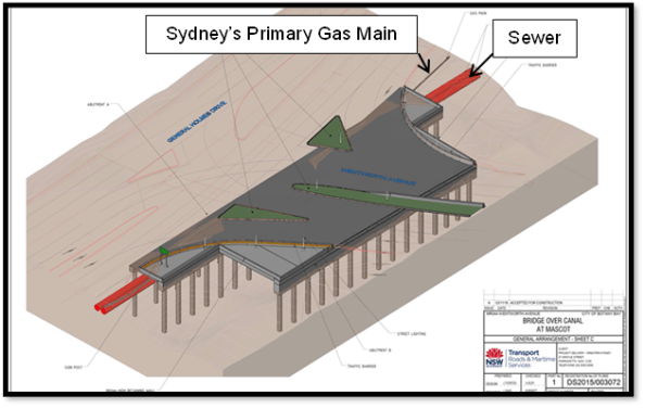
Figure 1 – Bridge Linking GHD to Wentworth Avenue Underpass
Vibration Management
The east runway is undergoing maintenance from 24 March 17 – 3 April 17 which allows the tall piling rigs to be set up. I have noticed rotary aircraft using the eastern side of the runway so have suggested that red warning lights (complying with Civil Aviation Authority Standards) are attached to the top of each of the piling rigs and included in the activity method statements.
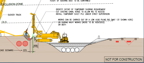
Figure 2 – Non-destructive Excavation & Sheet Piling Stage
A sheet pile wall will be installed adjacent to the primary gas main that will serve two functions (figure 2);
a. Retain the existing ground profile and allow for backfill around the gas main to eliminate any potential settlement or subsidence through piling and bridge substructure works.
b. To provide robust sacrificial formwork for the capping beam / pile cap.
Prior to installation of the sheet pile, non-destructive excavation was used to determine the exact location of the gas main and extent of stabilised sand backfill around the services (figure 3).
During the sheet piling, vibration monitors have been installed along the sewer and gas main to record vibrations which may occur. Limits of vibrations which cannot be exceeded for the gas main are 20 mm/s and 5 mm/s for the sewer. If the vibration limits do exceed this, a silent piling rig will be utilised. I have questioned these figures as I was asked to research ground borne vibration on buildings within the area and DIN 4150-3 limits peak particle velocity to 3 mm/s on sensitive buildings.
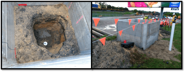
Figure 3 – Vibration Monitoring of Gas Main
The silent piler uses the ‘press in’ method, grasping the previously installed piles and establishing a reaction force from the negative skin friction and interlock resistance of the previously installed piles. Since the piles are pressed in this method does not cause any damage to the environment including neighbouring structures, assets or residents through noise and vibration.
Contamination
The project site is contaminated with poly-fluoroalkyl substances, known as PFAs. These are a group of manufactured chemicals contained in firefighting foam, they are added to improve the foams ability to smother fires. Therefore the likely source is Sydney Airport, the drainage for the airport runs through the site. The pathway and transfer of the PFAs is via the natural ground water flow through the site, and the possible receptors are workers and local residents as excavation occurs. They are a carcinogenic but are not found in high enough concentrations in the vicinity of the site to cause harm to workers.
Continuous flight augering (CFA) piling is being used due to the poor ground conditions and lack of cohesiveness of the loose, brown/grey fine to medium SAND. This method of piling stops the excavation collapsing due the concrete being pumped in as the helicoidal auger is extracted to give positive pressure to the excavation walls.
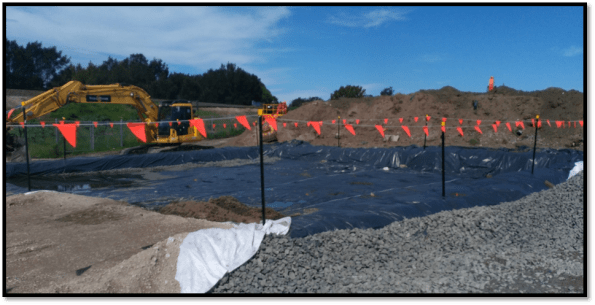
Figure 4 – PVC Barrier Layer for Spoil Heap to Limit Contamination
Excavated spoil is going to be placed in spoil heaps as to not contaminate the top soil. The PVC sheet is used as a separator and for the site to be compliant with the Australian Environmental Agency requirements. After looking at the design borehole (figure 5) for the site, I noticed the differing concentrations in PFA’s across the site. I have suggested that separate spoil heaps are created for different areas of excavation as to not waste money in disposal of contaminated waste which is has a different concentration of PFAs.
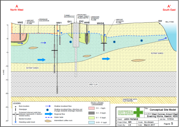
Figure 5 – Design Borehole for Site
CFA Piling Issues
As stated earlier the ground conditions are dictating that CFA piling is used. There have been some difficulties though when driving the cage into the poured concrete. Even though the water table is -3m AOD the loose, brown/grey fine to medium SAND is absorbing the moisture content of the concrete causing the concrete to cure quicker than expected. The concrete used has 240mm slump and aggregate size of 10mm (primarily to fit down the CFA tube). To overcome the issue 2m of concrete is being poured then immediately drilled out, lining the excavation with a layer of concrete to mitigate the loss in moisture content. Currently an excavator bucket is being used to push the cage into the concrete, but vibration of the cage is also being looked into. Thoughts on the use of a plasticiser?
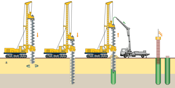
Figure 6 – CFA Piling Process
