Archive
What goes up…must be reused?
I’m on Phase 3 with Arup’s infrastructure team looking at urban redevelopment design so this caught my eye and got me thinking…
An article popped up on the company internal blog asking for design and construction experience of pre-cast RC multi-storey car park (MSCP). It stated the project drivers being programme and durability. Nothing out the ordinary so far.
A response was received within minutes based on recent experience that clients are now more aware of their social policy/agendas (sustainability) and constrained investment potential in ‘fixed’ structures. They state clients are favouring semi-permanent and flexible structures over traditional builds with greatest possible design life. The example given (below) was a ‘shape-shifting’ and deconstructable MSCP as the client sees autonomous vehicles making a traditional MSCP obsolete within a decade. This suggests design for deconstruction (DfD) and adaptability has the potential to be as if not more valuable to clients than durability…
https://www.cbc.ca/news/canada/calgary/east-village-calgary-parkade-platform-mixed-use-1.4855681
Planet. The design for deconstruction concept is founded on waste reduction so sustainability unsurprisingly. Technological development and sustainability incentives (UN SDGs) are driving up delivery efficiencies. Time-down, Quality-up.
People. The designing-in of deconstructability needs to happen at the project concept stage. Are rapidly changing attitudes and wider socials drivers such as autonomous vehicles (excuse the pun) triggering strategies away from permanent structures? Cost down.
Profit. Are clients/developers seeing opportunities in the two paras above to turn a quicker and more efficient profit? T-down, Q-up, C-down = Profit-up
Has anyone experienced similar quasi-permanent structures or concepts in their attachments? Any key considerations?
I wonder whether there is even utility in the concept for Defence – quasi-permanent bases for a decade or two say e.g. to deal with re-basing issues? Knowing defence, I suspect for the near future we will see more erratic rather than slowly evolving cityscapes instead…
H=0.5V=Sliding Modules?!
Company tour over, I was asked to design the spread foundations (not shallow) for a two-storey temporary lecture theatre facility for Swansea University. This is as their development strategy is 3 years behind programme. Albeit indirectly thesis related, it allowed me to refresh my soil classification and foundation knowledge as well as gain some pre-phase 3 calculation and design practice.
Foundation Design
This project is to be the first installation of their new RapidPlan product – a proprietary hot rolled steel framed box of 12×3.6×3.6m. Figure 1 shows the arrangement of a module (black box running left to right) and duplicated top to bottom. It will be 50mx36m. The different colour dots denote different column loads. There will be 83 foundation pads so standardisation, like the modules, is essential for design cost reduction and ease of construction. The aim is not to use deep foundations as the other tenderers are all proposing so to be very competitive.

Figure 1 – Arrangement and column loads (measurements in mm)
The Site & Ground
The site is reclaimed from the sea (100m) and exposed so peak wind velocity (qp) and shape factors (cs) are high. The ground has 100mm topsoil, then a 3m engineered piling mat (with sand fill) (which is strong – Plate Load Test to 365kN/m2 with only 1.25mm settlement) then medium dense sand down to 12metres. There is loads of PLTs, boreholes, trial pit and CPT data available. The piling mat is assessed as φ’=35o and SAND at 32 o. The ground is granular so has been treated as drained and is young so normally consolidated.
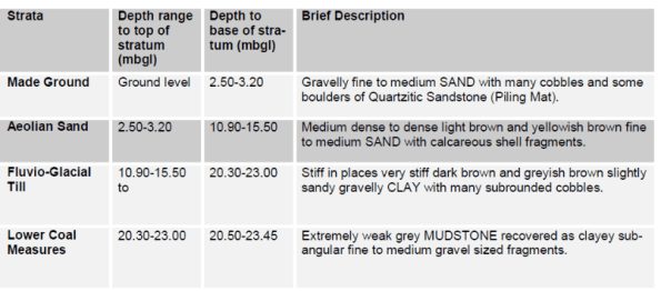
Figure 2 – Summary of Ground Conditions (WSP, 2013)
The ground water level is relatively static at 2.5m depth so is at the piling mat and sand boundary. This significantly reduces the strength of the sand (ϒ’=ϒsat– ϒdry) below that of the stiffer piling mat. Having initially used the presumed bearing capacity check (qp) from Method 2(EC7) the ground was deemed capable.
Loads
On lightweight modular structures live loads are often greater than live loads i.e. Qk>Gk. Column loads were issued by their structural engineers Fairhurst (used as a Phase 3 company before). This enabled limit state checks by Method 1. The 6no vertical loads, Figure 1, ranged from 64-440kN unfactored/service. Not a problem. However, the worst vertical to horizontal ratio at the base of the edge columns (blue dots) is 48%! I remember John saying that if H>0.1V then be worried, don’t get involved and see a specialist! Enter PET student…
Design Considerations

Figure 3 – Free body diagram
– A 1x1x1m concrete pad or paving slab is traditionally used to avoid using rebar and rarely with holding down bolts. A pad over strip foundation is planned because if L>B the zone of influence for bearing capacity increases from B to 3B deep.
– Each module uses moment connections (it’s a box that won’t tip over) so sliding is the module’s largest risk. Globally this means transferring 0.5H to the other longitudinal/transverse base. The column to pad connections are pinned.
– The sliding resistance (Rd only) from concrete to ground at 155kN/pad suffice compared to 64.5kN (0.5H). Passive resistance (Rpd) was not considered necessary at this stage.
Constraints
– It’s to have a 5-7year design life.
– The governing level is the FFL at the northern edge for level access. There is a 400mm level difference from northern to southern pads.
– The bases are to be at the minimum 450mm depth to prevent frost heave.
– I don’t want to go any wider or deeper than 1.5m as the saturated sand comes into play reducing GBC and increasing the risk of immediate (ρi) & differential (δ) settlement. Albeit the modules can manage 10mm.
Design Development
With the combined vertical and horizontal actions the two options considered (based on the site levels) are:
| Maximum pad thickness (1x1x1.5m) | Minimum pad thickness (1.5×1.5×0.5m) |
| + Increases surcharge load (qo) and so GBC | – Minimum surcharge load (qo) so GBC reduced |
| + Increases P with concrete self weight | – Decrease of P so GBC reduced |
| + Increases Rd and engages Rpd. | – Minimal sliding resistance (Rpd = 0) |
| – But increases moment (MH) & relies on Rpd | + Reduced moment (MH) |
| – Minimum depth of strong piling mat | + Increased depth of strong and stiff pile mat |
| – Increased concrete cost (3.4x) and installation | + Reduced installation time and cost |
| Risk is strength and settlement in the ground | Risk taken on effects of actions i.e. sliding |
Table 1 – Design options
I’ve used Geo5 to verify my ULS workings, but need to complete the SLS settlement checks which may be the determining factor. I have a preferred option and am hoping this forum will help confirm or quell my intentions. Especially as I’m still unsure about John’s H>0.1V… Any ideas? Or had similar issues? Or have I just slid you over the edge?
Realistically whilst there is an ideal engineering solution I am seeing first hand that the chosen solution is likely to be economically driven.
Phase 2.5 & Active Buildings
I am two weeks into my self-titled Phase 2.5 – a three week attachment with a privately owned company specialising in offsite modular manufacture and construction. This is as they, Wernick Buildings, are interested in developing a rapid foundation assessment method for low-rise structures i.e. my thesis. Essentially looking at quicker ways of assessing ground bearing capacity and settlement using a Dynamic Probing Light (DPL) (EN ISO 22476-2), a small and man-handle-able SPT (Standard Penetration Test). SPT is the energy required i.e. number of measured blows (N), to penetrate 300mm with a 63.5kg mass. For DPL it is 100mm with a 10kg mass. There is currently no widely accepted method to correlate the two methods. Obviously this has both civilian and military applications, hence the interest. However, after a tour of their factory and look around their main products/modules I was taken to their latest project, the UKs first energy positive building aka…
An Active Building producing Micro Energy
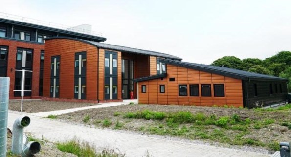
Figure 1 – ‘The Active Building Centre’s vision (centre) is to transform the UK construction and energy sectors, through the deployment of Active buildings powered by the sun, creating energy resilient communities, and significantly contributing to electric vehicle and decarbonisation targets.’
The Active Building Centre at Swansea University, is a new pan-UK university research initiative by SPECIFIC (funded by Innovate UK & EU circa £36m). It is to ‘reduce the cost and commercialise energy generation and storage components in buildings’ i.e. turn buildings into decentralised micro power stations. The ABC stored 29kWh and exported 47kWh back to the grid on the first day it was opened. This is the first building to achieve an A+ negative value on its EPC. It recycles its own energy emissions – what Building Emission Rate (BER)?! (Bld Regs Part L2A).


Figure 2 – The Active Building Centre’s live dashboard and EPC
A very apt concept when international carbon emissions are on the increase again after four years and on the first (actually second) day of the UN climate change conference COP24 in Katowice, Poland. Has Swansea secured a small chapter in the future of climate change?
True or False – Does this sit within the concept presented by Jason for his CI’s Essay on ‘energy storage in a non-fossil fuel national grid’…?
Quality – just one day a year?
On my Phase 2 at Victoria Square, Woking quality sits second on our client’s priorities after health & safety but above programme.
A lot of my time here has been spent addressing quality issues and it’s management. Having not long heard of this incentive on the project I wonder if anyone else has heard about it? And if so how our respective projects and offices across Ph 2 & 3 and the world are spending/investing in the World Quality Day?

At VSW we’re getting a presentation from the Project Manager and some light nibbles, well for the office staff anyway. Posters and graphics on the rolling screens in the welfare for the site teams… Priorities arguably a little off.
I did spot this on site however – a useful incentive to learn more than just swear words from the guys on site!

