Archive
Covid-19 Response; Temporary Hospital Design (Exeter)
You will all be familiar with the extraordinary efforts currently going ahead to complete the 4000 bed NHS Nightingale Hospital in London. Although on a smaller scale, my design office has just been stood up en-masse to provide designs for a 500-bed facility in Exeter. Whilst waiting for the URD to be issued, we’ve all been briefed to familiarise ourselves with the requirements specified in the document:
Having reviewed the document and other relevant sources*, I wanted to give a bit of an overview of what is required from an E&M perspective, as I think the design considerations would be of particular interest in the current climate.
All Patients with suspected or confirmed COVID-19 should be placed in single rooms as shown below.

The following design requirement/ considerations are per treatment room;
Medical gases:
- Patients will need continuous medical care using piped medical gases.
- The design must be factored around the source of supply; bulk liquid oxygen plant/mini tanks/portable cylinders.
- Medical oxygen supplies must achieve a flow rate of 10 L/min, per bed (implied task; check and confirm all distribution pipe sizes).
- Distribution systems must alarm if pressure drops below 3.85 bar
- Medical air manufactured using compressors on site. It is required for driving ventilators and is supplied via a dedicated pipeline system. In addition, medical air cylinders are normally used as an independent back-up supply.
Fire:
- The use of ventilators will result in increased oxygen levels with increased risk of combustion, which should be factored into a fire risk assessment.
- Temporary fire-stopping should be provided for any wall or floor penetrations.
- Automatic smoke detection is required
HVAC:
- The density of ventilators may enrich the air with oxygen, increasing the combustion risk. To mitigate this risk the level of air changes through natural and mechanical ventilation must be maximised to lower the oxygen level to <23.5%
- Where locations are considered “early stages” or “high-risk”, patients with COVID-19 should be isolated in “negative-pressure rooms”. The recommendation is to use portable suction units which can be removed and sterilised.
Small power:
- Each treatment room requires –
- 4 x twin 13A switched sockets
- 1 x 13A cleaners socket
- Each room has a number of electronic equipment, including ventilators, for which the combined loads will need to be calculated. Diversity will be minimal as all systems will run at the same time.
Lighting:
- Each treatment room requires –
- 20-20 lux general illuminance for night-time
- 1 x 1000 lux adjustable examination lamp
- Emergency escape route lighting required: In accordance with BS 5266 and HTMs.
Domestic Hot and Coldwater:
- Each treatment room requires a hand wash basin, which should be fed through a mixer tap.
- Max hot temp = 41 dec C
- Max cold water temp , 20 dec C
- Max pipework surface temp = 43 deg C
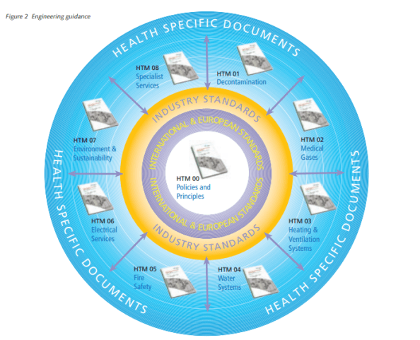
The above detail is just taken from the one document, but the HTMs go into much more detail and will provide the basis behind any designs.
I’m sure you’ll agree there’s quite a lot to think about there… and I’m looking at 500 beds, not 4000! As a standard project, on standard timelines, all of this would not be too challenging but when considered this is all to be completed within 10 days, you can imagine the challenges with design, supply, installation and commissioning. Not to mention the unprecedented level of collaboration and coordination required.
Although the treatment room designs can be replicated for each room, the distribution and containment networks for small power, lighting, water and medical gases will require careful consideration.
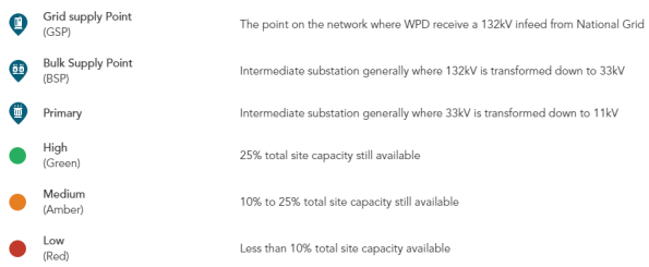
A major consideration will be the availability of supply from the local utilities companies and medical supply chains. The newly appointed site would have a much higher usage of water, electricity and gas. It will be important to calculate the requirements and engage with the utilities companies to ensure that the demand can be met. I know from recent experience that Exeter does not have a great deal of spare capacity in the electrical grid as shown below;

Hopefully, this has been of interest and given you some insight as to what is expected, with what I suspect might be the first few of many of these sites.
*A list of all relevant Health Technical Memorandums (HTMs) and Health Building Notes (HBNs) can be found on the UK Gov website HERE, but as a rough guide;
Non-standard Electrical Supplies
I stumbled across an interesting building last week whilst out on a Fire Compliance Survey. Within the Devonport Dockyard, Babcock have a building called the Central Frequency Changing Station (CFCS). This feature is responsible to the provision of “Shore Power” electrical supplies across the dockyard and HMS Drake Naval Base.
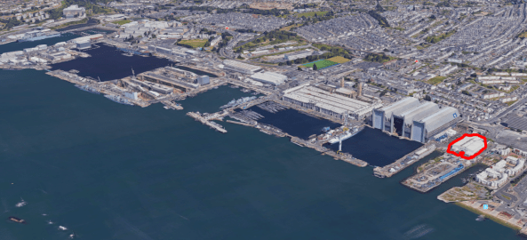
Devonport Dockyard showing CFCS building
Once large ships and subs are docked, there is obviously still a requirement to run auxiliary systems such as HVAC, lighting, battery charging, communications centre, computers and navigation systems. The vessels can provide their own power with their on-board diesel generators, but this results in noise, vibration and emissions as well as driving up running hours and using up vast amounts of fuel. The obvious choice is to just “plug them in” to a “shore supply”.
There is one slight issue; as the vessels make their way from international port to international port; the local power grid supplies can, and do, vary. Most vessels are designed to receive a shore supply of 6600 Volts at a frequency of 60 Hz. “Oh no” I hear the E&Ms cry! Here in the UK we use 50 Hz and generally a HV supply of 11 kV.

World wide electrical frequency standardisation 50 vs 60 Hz
So how do we get around this? Each “Shore Supply” is converted to 6.6kV at 60 Hz by motor-generator units. The CFCS building houses 12 x 10 MVA “common-shaft” synchronous-motor frequency converters.

Rotary “Common-shaft” Frequency Converter Units
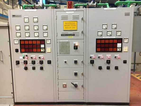
Frequency Converter Front Panel
Each of the sets uses a 50 Hz supply to produce an output of 60 Hz through the use of a “common-shaft” converter. Frequency conversion is achieved by winding the motor with a different number of electrical poles than the generator. A 10-pole motor and 12-pole generator are used to provide the conversion from 50-60 Hz . Using a synchronous drive motor ensures the frequency is maintained at a constant level to ensure power quality. Rotary units are selected as they are more reliable than solid state converters which create a synthesised output voltage and are prone to unwanted harmonics.
The sets give off a lot of heat which means the building requires heavy ventilation and the units themselves are served by a water cooling system which can be seen by the pumps and green pipework shown dotted around the installation.
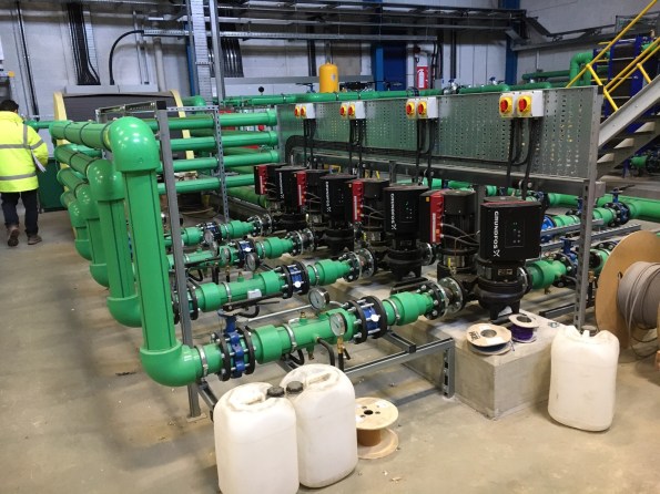
Circulation pumps for Frequency Converter cooling system
The 60 Hz supplies are then distributed via what I was told is the largest switch-room in Europe (citation needed!).
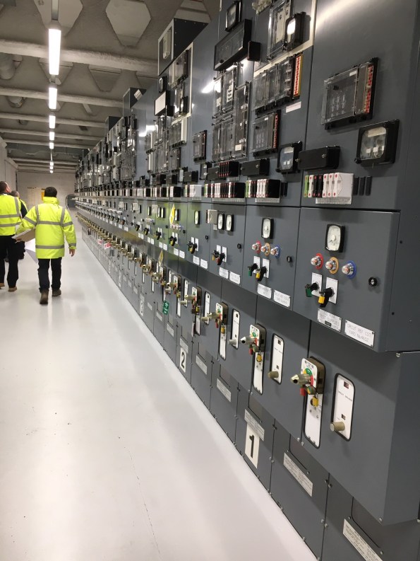
Dockyard Shore-to-Ship Electrical Supply Control Room
Just as a side note – A higher frequency is the preferred choice for many applications as motors and generators which run faster, have a better power to weight/size ratio and therefore take up less space. The same reason is why the aviation industry uses 400 Hz – smaller, lighter components for the same shaft power output.
What other locations or facilities are people aware of that have different supply requirements? Have you seen any “funnies” on your travels so far?
“Optioneering Study” – Drake Island Luxury Hotel and Spa
The What & Where
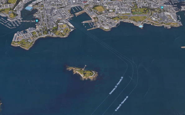
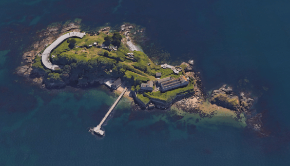
Having settled into my Phase 3 placement at a Plymouth based Building Services Design consultancy, I’ve been given ownership of a very unique project. Guardian Industrial UK (GIUK) as the client have purchased “Drake’s Island” sat in the middle of Plymouth Sound with a view to transforming it into a luxury hotel, spa and visitor centre/museum.
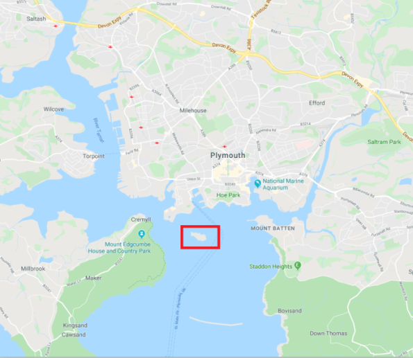
The six-acre plot is around 600m from the Plymouth shoreline and has a long history of being used as a Military defensive base . Originally constructed as a defensive fortification in the 16th century, it was also used extensively in both World wars to protect Plymouth’s Naval fleets. It was then used by the military as an Adventurous Training facility until it was closed down in 1989. Luckily Rob managed to get his Canoeing foundation qual there in 1988 before it closed. He hasn’t been to sea since.
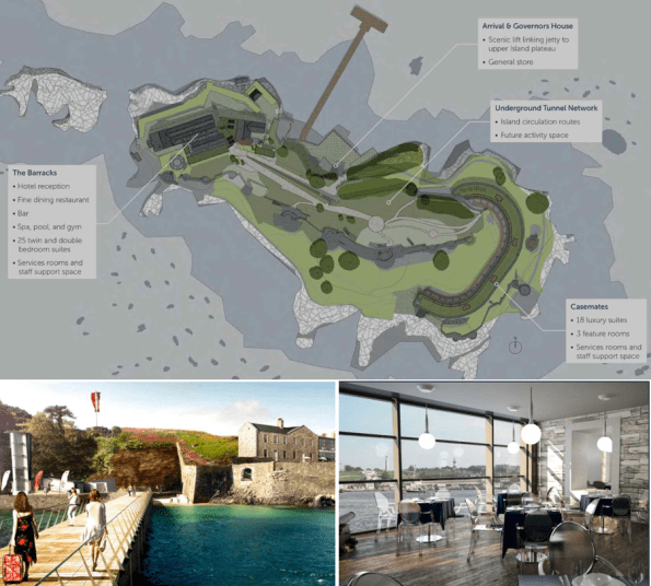
The Vision
I have a meeting with the client next week to try and tie down the scope. His intent at the moment roughly is shown below:
Restrictions
At present the site is derelict and pretty run-down. All buildings are Grade II listed and the island is home to endangered seabirds, fancy sea-weed and other rare aquatic wonders. The client has also stated a desire to make the island self sufficient through the use of renewable energy. Did I mention…
- The EA will not authorise a discharge permit for treated water (or so I’m told)
- Any untreated biological waste must be removed from the island EVERY 24 hours
- No diesel generators allowed at any time
- No outdoors areas are available to place additional infra
- No lift capability to move anything up the 12m rocky bluff perimeter, and no dedicated lay down areas
- The shallows/shoreline is off-limits
Pre-existing services:
Incoming electrical supply: 1 x 11kV submarine cable, laid in 1982, recently tested and ok but liable to deteriorate.
Substation and distribution: None
Incoming gas supply: None
Incoming water supply supply: None
Waste water treatment: None
Waste water disposal/sewers: None
Data/comms: None
The task:
So provide EVERYTHING to a place that effectively has NOTHING. Cool.
I’d imagine over the years that there have been similar challenges presented to RE officers when operating in different corners of the world.
My immediate thoughts are;
- Power
- Utilise the incoming supply with a pair of 11kV:400V “environmentally friendly” silicone/ester/resin filled transformers. This will be needed for all enabling/perm works and lighting from the outset.
- Research into “battery powered buildings” for renewable energy storage, design in low energy options to reduce load profile.
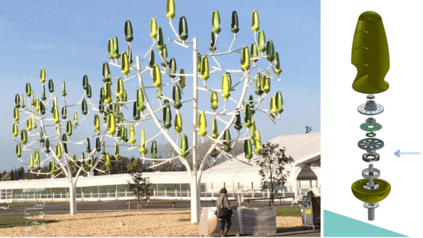
- Consider options for on-site generation such as “wind trees” and “bio-CHP”
- Water source
- Bore hole?
- Desalination plant?
- On-shore supply via pipeline installation?
- Waste water
- Will need to be taken away – heavy logistic burden
- Potential for treatment and recycling?
- Get on-site treatment right and renegotiate with EA for discharge licence?!
So I’d like to put it to the floor… has anyone seen examples, or been part of a team, required to deliver works/services/energy needs in particularly remote places? What advice would you give?
Or just any innovative suggestions to help me out (tech and/or logistics)?!
Point-cloud Data Capture for Tolerance Analysis of ‘As-built’ Structures within the HPC Nuclear Programme
The Main Civil Works (MCW) contract in place for Hinkley Point C (HPC) has seen a vast amount of concrete being poured, using vast amounts of rebar. Most rebar used on site was due to be at least 43mm in diameter but in response to lessons learnt in the Fukushima nuclear accident, the design has been strengthened in many places and now contains ‘double tied’ rebar – at least 86mm across. HPC’s civil structure concrete will also contain thousands of embedded items such as plates (90,000 of!), mounting bolts and ‘Halfen’ rails on which the many E&M systems, structures and components (SSCs) will be placed.
Due to the rebar situation, the MCWs are working off around +/- 80mm tolerances for their embedded items. The E&M execution designers and installation contractors are working off +/- 2mm. Anyone see an issue here?
The simple solution is to assess where tolerances are out of spec, and present this information to the E&M SSC execution designers to mitigate (design-out) the risk. To this end, accurate 3D positional data is required for the thousands of MEH related support items embedded within the MCW structures.
This issue is a long way towards being resolved through the application of 3D point-cloud data-sets which can be analysed using an innovative new software platform called…


The ‘as-built’ civil structure point-cloud is fed into the software tool alongside the design data for the structure and each embedded item. The software then provides a 3D ‘trueview’ of the structure and will indicate where embedded items are IN or OUT of tolerance using a traffic light system as can be seen in Fig 1. Each component can then be analysed to check its actual position (x,y,z, coordinates). The fact that almost all plates are out of tolerance on the left wall would suggest the wall is probably in the wrong place!
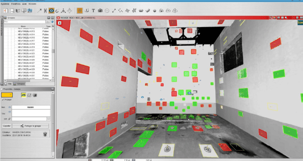
Fig 1. Tolerance analysis of embedded plates within a concrete structure using “My-Survey DAC” by Quadrica
Fig 2. then shows how a deep dive analysis can be carried out for each specific embedded item with clear reference as to where the design coordinates ‘should’ be and where the actual as-built condition has found them to be in reference to the tolerance parameters.

Fig 2. In depth analysis of a specific embedded plate to show design coordinates, actual ‘as-built’ coordinates and deviation from defined tolerances.
It is also possible to perform CAD model component overlays onto the ‘as-built’ structure as shown in Fig 3. to conduct interface control and to assess the impact of out of tolerance walls, openings, doorways and/or embedded items.
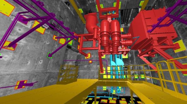
Fig 3. CAD model overlay on to ‘as-built structure’
In developing this methodology, a number of potential benefits have been identified:
- Access to ‘as-built’ data much earlier
- Single point data acquisition, analysis and use. No requirement for SSC installation contractors to conduct their own scans to understand the ‘as-built’ condition
- Early identification of potential problem areas
- De-risk support design and allows for fabrication at source
- Additional cross-project as-built benefits (Lifetime Quality records and Building Information Modelling)
As such a financial saving of £40-60m is predicted throughout the HPC construction from contingency funds associated with risk mitigation.
As well as structural tolerance analysis there are also a number of other applications such as:
- BIM modelling
- 3D CAD/mesh model generation
- Production of isometric drawings
- Volume surveys (earthworks)
- Clash detection
- Final ‘as-built’ survey
- Deformation surveys
- Reverse engineering
- Orthophoto or “Trueview” 3D imagery
- Virtual/augmented reality
- Walk/fly through orientations
Having had to conduct a lot of research before going firm on the “My-Survey” software platform it was surprising how many different software platforms are available on the market now for use in point cloud applications (see Fig 4).
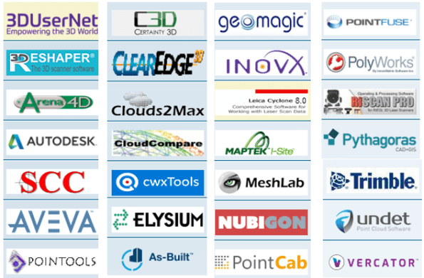
Fig 4. Various point-cloud analysis software platforms
I’d be interested to hear if anyone else is familiar with any and if there are any innovative applications as to how they are being used (turns out I’m writing a thesis on it all?!)?
Bigger is better?
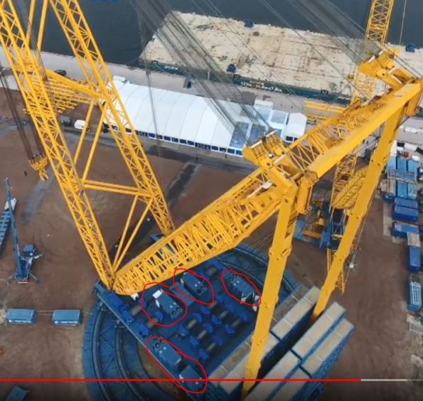
Having got to grips with the EDF Hinkley Point C (HPC) Nuclear New Build (NNB) programme now I can tell you that every day it blows my mind as to the scale of what is taking place. Everything is in excess. For example, it was decided that if the reactor dome could be constructed away from the reactor common raft, before being lifted into place when on completion, it would allow multiple works packages to run in parallel, saving time and therefore cost. But how do you lift something like that into place when it’s ready? Easy… you use the Sarens Super Crane!
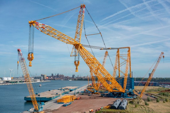
The Sarens SGC 250
The crane has a maximum load moment of 250,000 tonnes, allowing it to lift 5,000 tonnes at a radius of 50 metres. Even at a larger radius of 100 meters, it can lift 2,000 tonnes. Although at 100 metres, it wouldn’t stretch far across our site – so its going in on rails to transit between 3 separate 360° slew points.
Its difficult to find a photo perspective that does it justice but the Sarens link here does a pretty good job; https://youtu.be/BHwbu8iWrBo
Update in response to comment: Power is supplied ‘on-board’ using gen-sets…