Archive
The Good, the Bad and the Ugly.
It’s been a while so it’s time for another blog.
There has been a bit of a shift within the team as 2 of the Assistant Structural Engineers handed their notices in and left rather quickly resulting in a team of 4, under the Senior Structural Engineer, being reduced to me and one other. This has clearly increased my work load but frustratingly not entirely in productive areas.
The Good.
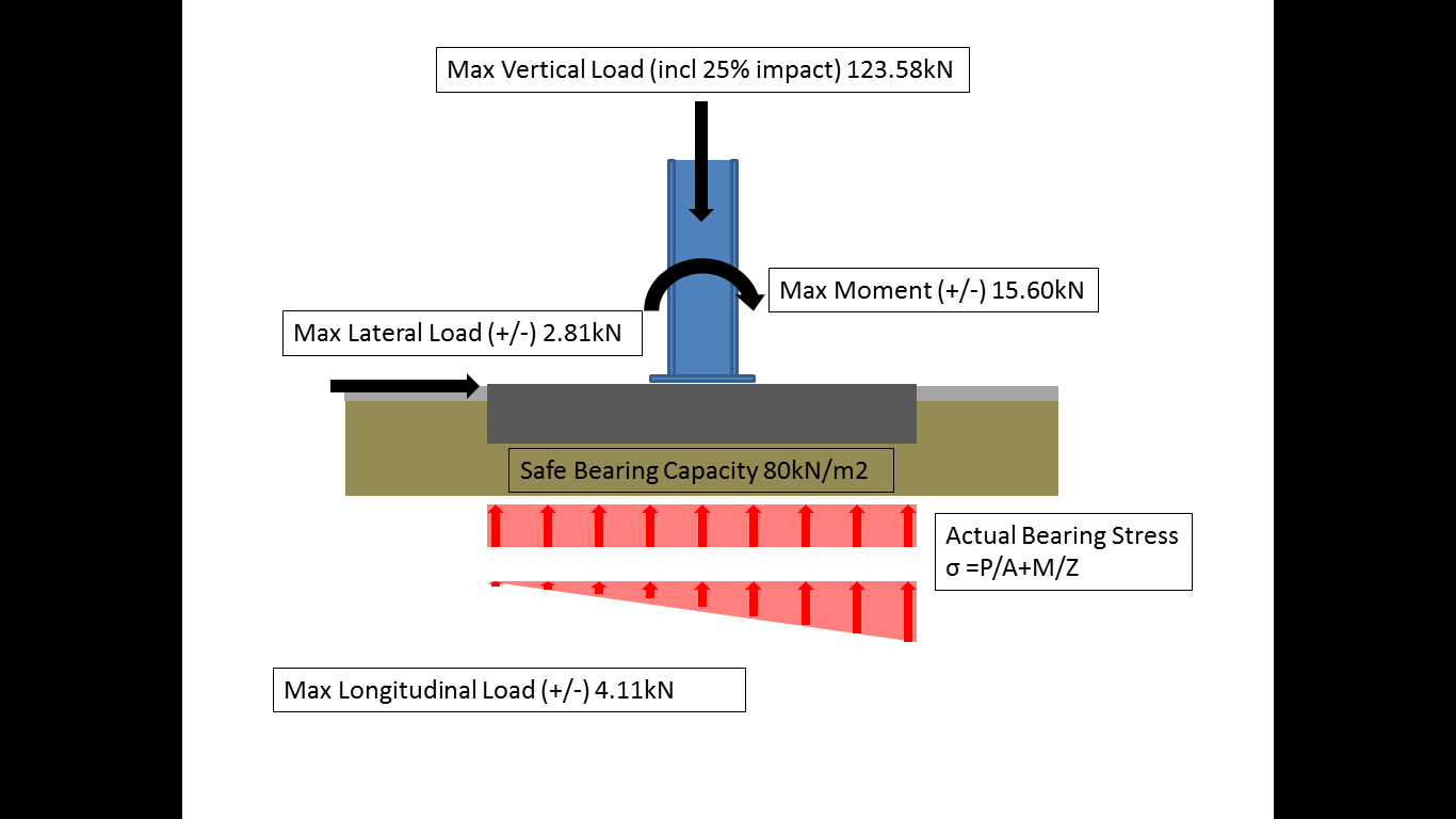
So the subject of my previous blog was an independent foundation design for a standalone gantry crane that I initially completed by hand as practice before inputting into the computer analysis software Masterseries. I completed this design and sent it to the client with my recommendations as their proposed orientation could not be accommodated due to the foundation size required and the existing building geometry. This has since been returned with a slight amendment and is sat in my in tray to look at their new proposal and make the design amendments accordingly.
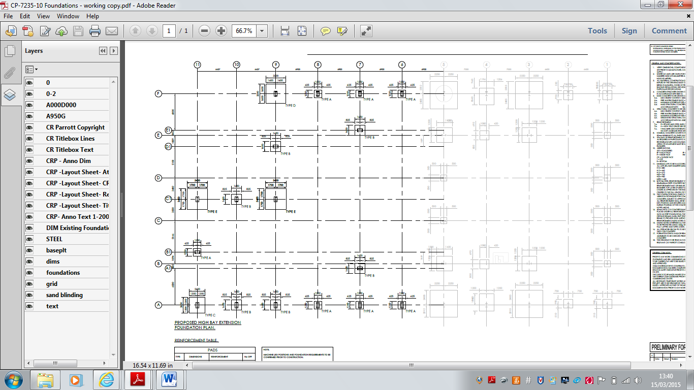
This process led onto my largest design responsibility to date. I was required to design the foundations for a second 4 bay 7.0m x 35.0m extension to an existing portal frame building. The original building and first extension were completed by CRP so much of the design input was already available.
The first stage was to take the existing building footprint and set out the new nodal positions and detail appropriate section sizes based on the original frame as the steel section design information was unavailable. I had however received the loads from the steel designers, as nodal loads, (which made life easier) and allocated those to the frame accordingly. I made an adjustment to the surcharge load from the original due to a different slab requirement and dug out the original site investigation report to ascertain the ground conditions and safe bearing pressure of 225kN/m3. This indicated a layer of chalk at 1.5m from the underside of the slab and I decided that this would set the depth of my foundations. Once these parameters were established I individually designed the 16 foundations required before economising the design for ease of construction by reducing this to 5 different sizes. Partly due to the specified depth, I was able to negate the use of steel in the design and recommend the bases were constructed from mass concrete, thus reducing the cost. Once complete I submitted the design to the Senior Structural Engineer for a few tweaks before detailing the drawing in AutoCAD and sending to the client for discussion and approval.

Frame Complete.

Sections Allocated.

Loads Applied.
Drawing Complete.
I have also managed to get involved in a number of other areas of work that the consultancy cover.
I have worked on the preparation of a number of tenders in particular the drafting of remedial work specifications for small domestic and commercial projects. I have also been appointed Assistant Project Manager for a couple of local refurbishment projects. The first a £120,00 upgrade of a Day Centre, the second a £1m upgrade of a existing steel portal frame warehouse. Both of these jobs came about from my discussions with the MD to complete DO C5 (Managing Contractual Issues). I wanted to work on small scale, local projects that I could possibly see through during phase 3 and would allow me interaction on site. Whilst I was initially reluctant to be involved in the projects, as I did not perceive them to be engineering heavy, I have subsequently realised that they fulfill the requirements for the DO more than adequately. My work across both projects has included; feasibility studies and work specifications for tender, contractor hosting on site, return tender assessment, prestart meetings, liaison and coordination between the clients and the contractors during works, quality management and assurance on site (C4) and a host of other smaller tasks. All of which have contributed to finalising a number of outstanding DO’s.
The Bad.
Due to the 50% reduction in engineering staff in the office I have had to take on some additional drafting responsibilities. Whilst not hugely significant much of the design I am currently conducting I subsequently have to detail in AutoCAD. The 2 Engineers that left used to do much of the detailing to assist the CAD technicians (who are also undermanned) and hence the task has fallen to myself and the other Assistant Structural Engineer. I have voiced my opinion on this but equally understand that it partly comes with the territory and responsibility of working in a small, very busy consultancy. The issue will shortly be resolved however as 2 new CAD technicians start next week, one of whom is an ex RE draughtsman. I hope he brings his own sandbag for my war dits as they’re just not appreciated by civilian engineers.
And the Ugly.
It is something I realised on phase 2, but even more so with the projects I am working on during phase 3, there are plenty of opportunities to complete the DO’s, even in areas that are not immediately obvious if you push for them with your placement mentors. I am gaining a wide range of experiences on phase 3 and although I am not churning out impressive designs for half of London like Richard, or Riyadh Metro like Steven, I feel I am getting a rounded consultancy experience, akin to the type of activities we may be conducting when back in the green. I have continually sought to shape the direction of my placements, guided by the DO’s, by being outright and robust with the various MD’s and PM’s who I have found are generally receptive to my requirements. I would recommended this to the current phase 2’s as it is easy to become stove piped by companies as you show competence for the conduct of particular engineering activities and you suddenly become the ‘piling go-to guy’ and that’s all you experience in phase 2/3.
Phase 2? Done. Hello phase 3.
Well I thought I’d kick off the New Year with a blog and step off with the right intentions.
I’ve been in the design office a couple of weeks now and it’s been fairly gruelling to say the least. Reading back through some of the blogs from this time last year it appears that the majority of the PET(C) 60 course experienced the same mixed feelings at the start of phase 3, with some hilarious inputs from Rich Phillips.
So I have started work with a small consultancy located in Scunthope, NE Lincolnshire and have quickly established that I am not cut out for the daily commuter grind and office environment.
The consultancy, CR Parrott Consultants Ltd was set up in 1994 by Chris Parrott (MD) as a structural engineering consultancy as he is a chartered structural engineer. Over the course of the last few years the company has steadily expanded and now employs approximately 30 staff across 2 offices. The company now offers a professional engineering consultancy, project management, technical support, architectural and 3D visualisation services. This is quite a broad spectrum of activities for a small workforce but reflects the nature of the work in the area as Lincolnshire is not renowned for its cutting edge civil engineering.
I have been placed in the structural engineering design team, headed up by the senior chartered (IStrucE) structural engineer with 3 further assistant structural engineers from various backgrounds. The size and nature of the company means that I am likely to get a good spectrum of exposure to the different consultancy disciplines with a real chance of being able to construct something I have designed during the 7 month period.
I spent much of my early time in a similar vein to the early days of phase 2, looking through job files and drawings, attending a number of briefs and re-sharpening my academic pencil. The Senior Structural Engineer set me a number of revision topics and seminars to work through for my first few days and over Christmas leave (!) predominately focussing on frame analysis and steel and timber design. All good stuff for the CPD log.
Last week I was given my first real design responsibility and it came in the form of a foundation design for an overhead span crane to be constructed inside a steel portal frame hangar. The initial job entailed a detailed survey and structural report on the existing crane runway beam positioned inside the building to ascertain whether it had sufficient strength to accommodate a larger crane (from 2.5T to 10T). It did not. This work was completed by the Senior Structural Engineer and the analysis revealed that the existing foundations and crane runway beams would be overstressed and incapable of taking the additional loads. A number of recommendations were made including a C-Section steel top hat surge girder on top of the existing beam (to improve the stiffness in the yy axis) or the use of RSA or CHS between the portal columns to reduce the effective buckling length of the beams. Both of these options were discounted due to the amount of additional work required to facilitate the construction due to the access limitations. This was sent to the client who subsequently came back to request a bespoke crane that will sit inside the building footprint. Whilst the consultancy would normally design the steel frame for the crane, this has been subcontracted out to the crane company who have an ‘off the shelf’ solution. This makes our life easier as we get the frame dimensions with the static and dynamic loads clearly set out, reducing our analysis time.

Existing crane runway beam.
Foundation Model.
So the first job was to assess the buildings footprint and establish where the crane would fit in the area specified by the client. This raised a number of issues including the clearance of the new crane under the existing and the proximity to the ground beams running underneath the portal frame columns. The building plans were located and the existing slab (180mm) was analysed and it was established that drilled and grouted bolts in this slab would not be sufficiently strong to accommodate the frame. So the plan is to locate an area where the frame will fit (in-between a number of drainage channels, not inside the ground beam footprint), break out the existing floor slab and construct some bespoke foundation pads for the frame columns, tied into the existing ground slab. Simple enough and a perfect warmer for yours truly. I have now completed the preliminary calculations for a RC foundation and await the familiar red pen of the Senior Structural Engineer prior to inputting the data into Masterseries for final analysis. I have also started the AutoCAD drawings that will form part of the portfolio of work that the client will receive. The following are a couple of reflections on my time and work to date that also form part of AER 4.
Reflections:
Design. It has become quickly apparent that it is much tougher to design structural elements within existing infrastructure than on a clear site or on in an academic environment. Whilst an obvious statement the challenge lies in understanding the design fundamentals enough to manipulate them as necessary to accommodate a functional yet cost effective and economic design. This is something I feel I am already learning and will come with practice and experience.
Seminars. During the first weeks of phase 3 I was given a number of design tutorials to work through, predominately in timber and steel design, to catch up with the other Assistant Engineers who had already taken the sessions. The seminars are led by the Senior Structural Engineer and occur on a weekly basis for a couple of hours in addition to a number of Masterseries training sessions that occur less frequently. These sessions have proved invaluable, not only as a good revision period but as useful hours towards my Continual Professional Development (CPD) Record. It is also a worthwhile personal lesson to see even relatively seasoned design engineers refreshing the fundamentals of design and highlights the importance of combating skill fade. This will inevitably be all the more important as a Professional Military Engineer and highlights the importance of maintaining a thorough CPD.
Software. The structural software utilised by CRP is the Masterseries design suite and whilst more complex than StaadPro, with a greater level of modelling detail that can be incorporated, the fundamentals are similar. The availability of the software across the team is limited and whilst the software is loaded onto each computer in the office a pen drive ‘key’ is required to open the software. This is controlled by the Senior Structural Engineer and seems to limit the amount of work the Assistant Engineers can do. I am yet to ascertain whether this is a product of licensing cost or a form of quality control across the team. The software has more applications that STAADPro and would be worth considering if the PEW system was ever upgraded.
British Standards v Eurocodes. The structural team work to the codes laid out in the British Standards not the Eurocodes. Whilst this is still a legally accepted practice it is frustrating to have to relearn the BS methodology after an MSc focused on the Eurocodes. This was the same as the design calculations produced by the design consultancy during my phase 2 attachment with Graham Construction. The only conclusion I can draw from the lack of adherence to the Eurocodes is the generation of Engineers conducting the designs and their reluctance to accept the change and embrace the new codes. I suspect it is also a product of the small nature of CRP as many larger international consultancies will undoubtable have made the switch to cater for their wider clients. The seminars have assisted in adjusting my mindset back to the BS.
Judgement. It has become apparent that there is a certain amount of license to make an ‘engineering judgement’ when it comes to structural design. Whilst it appears that the process is strictly governed by the handrail provided by the British Standards and Eurocodes there are times when engineering judgement is used to make a decision particularly in geotechnical engineering. This is something that partly comes with experience for which there is no substitute.
Experience. Whilst design Engineers may have an ability to make a design judgment, it has quickly become apparent that they can be quite focused on their particular part of the project and do not necessarily understand the larger project for which they are part. Constructability is an area that is not well understood and is generally brought about by a lack of on-site experience and a post graduate career dominated by the design environment. These puts us in a relatively strong position, as a more rounded engineer, especially post Phase 2 and seems to offer a different dynamic to the consultancy environment.
I feel that I have a good opportunity at CRP to be involved in a number of designs ranging in scale and complexity. Despite the small size of the company there is a good learning ethos across the structural team and the company are fully on board with my requirements to achieve my outstanding development objectives.
Better late than never.
This blog has been sat on my laptop awaiting publication for some time and whilst now out of date I think it is still worthwhile publishing. Much of this also formed the basis for AER 3 so you can exit at this stage if you have read that document! I wrote this towards the end of my time at Graham Construction in mid November.
I have reverted to publishing this blog as my brain is aching after being set a timber and steel construction tutorial by the senior chartered structural engineer, who’s office I have been moved into and sit directly opposite. Joy.
Blog from mid-November.
The last few weeks have seen me of focussing on trying to eliminate a few outstanding development objectives that I need to have achieved by the end of phase 2. I have been concentrating less on the physical construction of structures that dominated my previous time on site and more on the commercial and managerial aspects of leading up to the construction activities.
Sub Station 18.
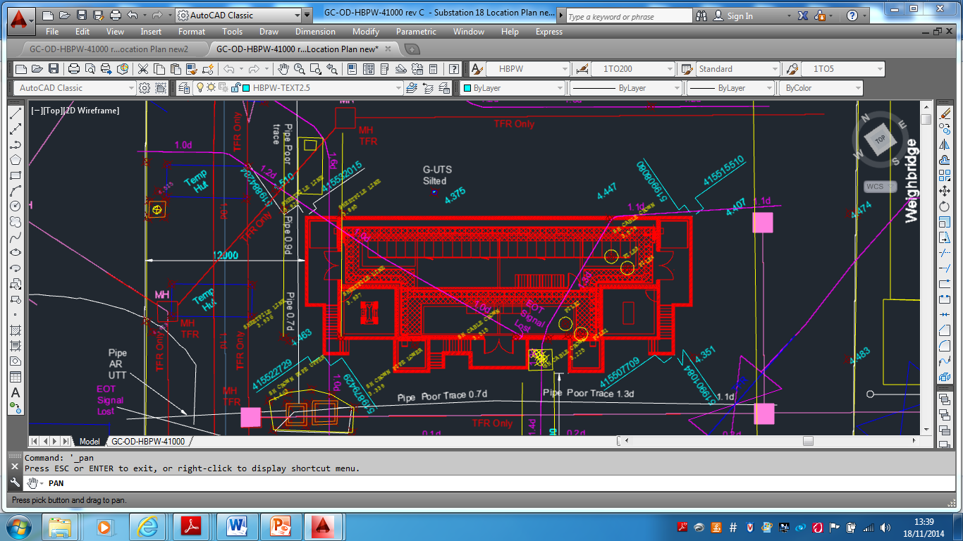
I have mentioned on previous blogs that I have been given an independent command of a small sub-station at the east end of the docks, a couple of miles from the current IRFT site. Whilst not the largest project in terms of real estate and value it has allowed me to take a project from proposal to the early stages of construction. I will not see it completed but have assisted in building the 2 other substations on the IRFT site and as such it will allow me to hit the DO’s I am short on.
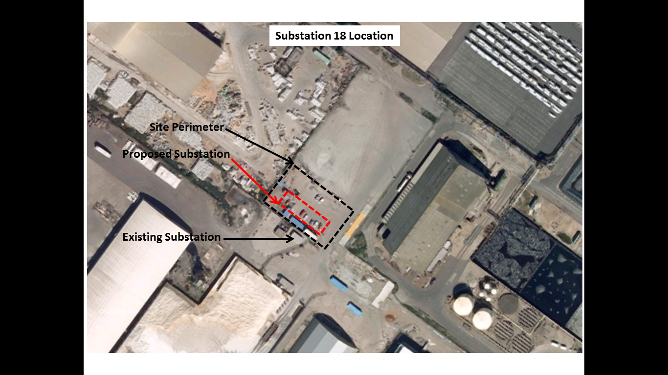
Sub 18 Location
Proposal.
The new substation is required to replace an existing substation situated north of the chosen site that was subjected to extensive flooding during last winter’s tidal surge up the Humber Estuary. The location and pre-tender service drawings have been provided by the client and the design has been produced by the consultancy for the QS’s to produce a tender price (approx. £300,000). The contract has yet to be awarded but ABP were keen to conduct a site investigation in the proposed area in the knowledge that the location is a well-used brownfield site with a legacy of industrial use. There are a number of documents out there on how to conduct a site investigation. I referred to the AGS (Association of Geotechnical and Geoenvironmental Specialists) for guidance and used their checklist for site investigations to keep me straight. http://www.ags.org.uk/aboutbusiness/bestpractice.php
It is likely that that the contract will be either a variation order to the IRFT contract or a negotiated contract due to the specialist skills accrued by Graham in construction of the previous substations to the ABP specification. This would reduce the costs of tendering and has allowed for early contractor involvement. Whilst the competitive element is reduced the relationship between ABP and Graham is sufficiently strong to allow for robust negotiations. Until the contract is formally awarded all the works I have conducted have been charged to ABP through Operational Record Sheets but if Graham win the work the cost may be negotiated into the overall tender price for the construction due to the increased rates on an ORS.
My first task was to hold a meeting with the client to firm up this detail and then walk the site with them to understand their intent as part of the pre-tender process. I then wrote a RAMS covering the set up and establishment of a new site, reviewed the substation construction RAMS from the previous builds, drafted a programme of activity for the set up and works and completed a number of permits for excavation and working around live electrical services.

Sub 18 Programme of Activity
Feasibility.
Desk study.
My pavlovian response to approaching and shaping the SI was ‘what are the risks’ both technically and from a commercial prospective, financially? The pre-tender service drawings provided by the client were clearly dated and inaccurate but gave a good enough picture of the number of services that I may encounter during any investigation works. This led to the early conclusion that the main risks would be to the cost of the project in dealing with the services and not necessarily the risks posed to the design by the soil properties. This notion was strengthened by my previous experiences during my construction activities at the IRFT having had no issues with the ground (apart from a few broken piles!). Whilst the preliminary design was completed I could directly influence the final design through the findings during my GI. The structure itself whilst over 8m in height, has only the cable pits and ground slab, approx. 2m worth of structure below the current ground level of 4.4m AOD. Despite my confidence I did know that it was important to understand the groundwater regime and so got onto the British Geological Survey’s website to locate the nearest borehole to my site. The boreholes were 1947 trail water boreholes and indicated a rest water level of approximately 3.0m AOD close to my site. This made sense given the proximity to the docks, mean tide level and previous experience. The boreholes also indicated that the surface strata comprised top soils with black mud followed by varying depths of stiff clay and pebbles. The stiff clays feature from around 3.5m AOD, approximately 1.0m below the ground surface and due to the water level would demonstrate undrained fine grained material properties. This gave me the confidence that the strength during any excavation work, unloading the soil (short term) would be sufficient. Due to my previous excavations on the main site, in similar soil conditions, and the obvious low permeability I was also confident that any water seepage could be controlled by the standard 2” submersible pumps. This information furthered my notion that the risks in the ground were unlikely to come from that material properties or the groundwater regime. It was clear to me that the risks would be in what we physically found in the ground both to the excavating team and the cost.
The next phase was for me to check the historical records and identify any existing services which was easier said than done. The historical drawings provided by the client were dated and only included recent client constructed additions to the site area and not a great deal of legacy information. However I complied what data I could find and found that the best results were obtained from my site walkabout to ID manholes, resurfaced channels, lighting , inspection chambers etc and then chatting to all the ‘old boys’ working in and around the site who provided a wealth of information having worked on the docks their whole lives. This was all compiled into a working document as the initial stage of the GI report.
Design. Phased Investigation.
Non – intrusive Investigation.
Once I had gathered all this information I contracted SUBSCAN (Sub-surface survey contractor) to complete a GPR survey of the entire area, based on my previous experiences (HV strike) and the proximity to the existing substation to be replaced. Once again the GPR survey proved its worth as a substantial number of unknown electrical and non-electrical services were identified that were not shown on any drawing or identifiable from the site walkover I confirmed the location of these services with the CAT SCAN and then did my best Art Attack effort with about 5 tins of spray to highlight every known service prior to any intrusive investigation.
Intrusive Investigation.
The next phase was to dig a number of trial holes and slit trenches to expose and confirm the services, their condition and generate a solution to dealing with them. This is where the true extent of the services was revealed and we found a whole host of legacy pipes, cables, piles, manholes, concrete chambers, railway lines etc. It took a couple of weeks to actually expose the full extent of what we found in the ground as the more we looked the more we found. Even after a thorough desk study and non-intrusive survey I still found unrecorded services but we had no H&S incidents. I also took samples for contamination analysis and sent them to ESG for a full suite of tests. At the end of the intrusive investigation it was clear that the clients proposed sub-station location would involve a substantial amount of ground works to accommodate the structure. This work included temporary diversion of 5 electrical cables, removal of a 20mx5mx 3m deep concrete chamber built inside an insitu steel pile cofferdam housing 2 x Victorian cast iron power station water cooling pipes (500&750mm), a railway line, 8 PC RC piles, 4 cast iron water pipes and 2 associated manholes and a number of drains. None of this work was expected and would be added to the tender cost.
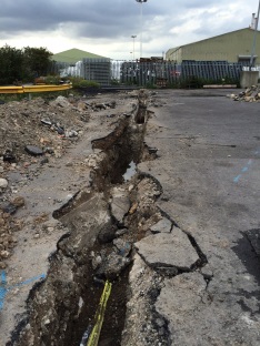
Sub 18 – Intrusive Investigation
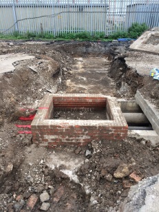
Sub 18 – Intrusive Investigation

Sub 18 – Intrusive Investigation
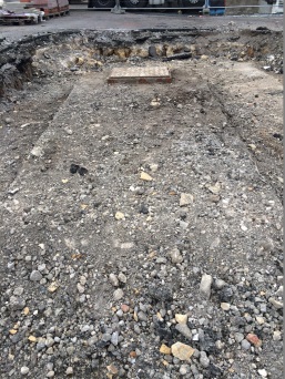
Sub 18 – Intrusive Investigation
Geological Report/Interpretation.
Due to the speed of the discoveries I kept a drip feed of information flowing to the design co-ordinator and the clients representative, holding a couple of meetings to discuss my findings and suggesting the best way to proceed. At the end of my intrusive investigation I put together a powerpoint presentation and CAD drawing to summarise the points I had written in the geotechnical report that I had been concurrently writing on the site. I found that this was the best way to portray my points clearly without having to trawl through a full geotechnical report. I recommended a shift in the substation location that would minimise the amount of work required to relocate the services thus reducing the cost and construction time. I plotted this out on the ground and walked the client through the proposal. I outlined where I thought there were still risks to the construction and design which were predominately focused on access for construction and subsequent installation of the transformers and the undermining of the various services to get all the HV lines into the substation whilst maintaining the minimum 1m cover. I also fed these point back to the design co-ordinator.
Sub 18 – Results of Non Intrusive and Intrusive Investigation

Sub 18 – My revised location republished by the designers for client approval
Detailed Design.
The detailed design was published last week and the client has now completely revised the location. The substation has been moved to the west of the current location, inside a restricted fertiliser handling facility. The driver behind this decision is the expected cost of the ground works required, even with my revised location, and the value of the site for future commercial use, when compared to the new location. In my opinion there will not be a saving in the ground works as the new location is likely to be as service ridden as the previous but I suspect the future proofing of the location and cost of land is the main factor. This is especially the case when you consider the works we have subsequently conducted to re-instate the trail holes (backfill, 150mm aggregate, roadsaw to cut straight edge, tarmac subcontractor to re-surface, etc) not to mention the asbestos I found and have subsequently had removed on the second site walkover.
So I am now repeating the process. I have edited my RAMS for site establishment, completed my site walkover, amended the desk study and re-contracted sub-scan who are in today.
So what did I learn?
Despite being slightly frustrated at having put in so much work on the initial site for it to be moved, I completely understand the long term commercial consideration on future land use and rental potential. However I am convinced that greater analysis by the client at the proposal stage would have highlighted this consideration and saved them a not insignificant amount of money on the work to date. I have yet to receive the updated costings from the QS team, but it is likely all the SI and subsequent reinstatement work will cost approximately £40,000. This is not including a figure for the SI work still to be conducted for the new location and is a significant additional cost for a £300,000 project. In the green, it’s not even a question 4 moment, as the situation hasn’t changed, in this occasion the fault lies with the BGE as there has clearly been an inadequate IPB. Sorry for the stinking chat.
When given the task, I looked for a handrail and was surprised to find no national specification and method of measurement for site and ground investigations. It would have been useful to have had a one hit document based on current ICE specifications but augmented to accommodate the philosophy of Eurocode 7. There are any number of GI handrails available written by a host of private companies, local authorities and geotechnical experts but I was surprised by the lack of a coherent national document especially to guide non geotechnical engineers through low level site investigation. Exercise Cofferdam formed the basis of my knowledge on the compilation of a geotechnical report.
This leads onto my next point as it struck me as the type of activity I may undertake when back in the green. Whilst not hard core geotechnical engineering involving interpretation of material properties and utilisation of that data for design, the nature of the investigation and commercial considerations have been an important lesson. I can envisage similar circumstances where it is unlikely that we will have a true geotechnical engineering specialist available but there is the requirement to assess the risks in the ground , both physically and commercially and communicated those accordingly to a client.
Now back to my web buckling checks…..
Only 12 x slower than the common snail.
The slipforming has commenced on site again for the four additional silos required for IRFT 2, the £60M variation order that includes all the associated infrastructure.
I have not been heavily involved in the slip, as I’m not in the section responsible, but I thought that it would make interesting reading and a good comparison to Rich’s earlier blog.
The silos range in height from 52.524m – 63.107m AOD and the actual slip height’s are 46.924m – 58.457m respectively. The internal diameters are 37.5m with a wall thickness of 450mm. Silo 6 (50.424m slip height, 2705m3 of concrete) was the first to be completed and it took a remarkable 168hrs almost exactly from approx. 0700hrs on Mon 29 Sep through to 0700hrs Mon 06 Oct, 3 days ahead of the programmed 10 days. That’s an average of 300mm an hour or 16.095m3 of pumped concrete an hour, only 12x slower than the common snail at 83micro m/s. The teams are currently running in 2 x 12hr shifts maintaining a 24hr continuous pour, 7 days a week. It is reputedly, the largest continuous pour conducted in the country this year. There are 2 sets of slipform equipment so within 30mins of completing silo 6, silo 5 was started. This will be repeated for silos 7 and 8 and should therefore be completed in 40 days and 40 nights of continuous concrete until over 10000m3 has been poured.
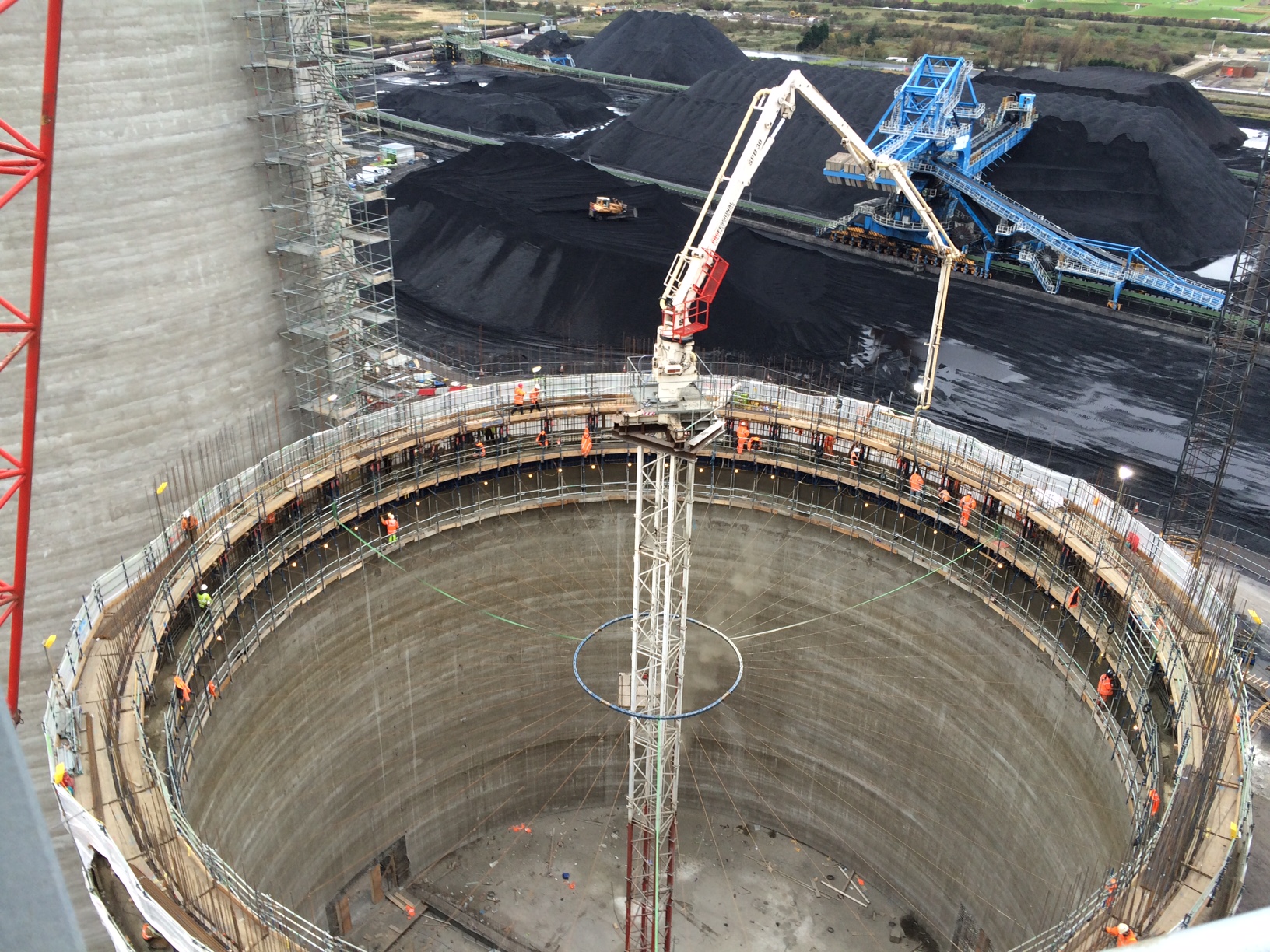
Inside the Silo slipform.
The slipforming platforms are on 3 levels. The upper level is used for the placing of the 20mm vertical steel bars (that are at 3 different heights, meaning only a third need changing at the same time) and the solid slip bars, that the jacks run up, that are placed inside the wall and cast insitu to be jacked out once complete. The middle level is the chaotic level (as Richard mentioned in his blog), where the concrete is pumped into the shuttering, the 25mm horizontal steel bars are placed and the actual slip is controlled. The shuttering is 1.2m deep. The lower level is used for rubbing down the concrete after the slip shuttering has moved upwards to create the specified finish. There are never less than 45 guys on the decks.
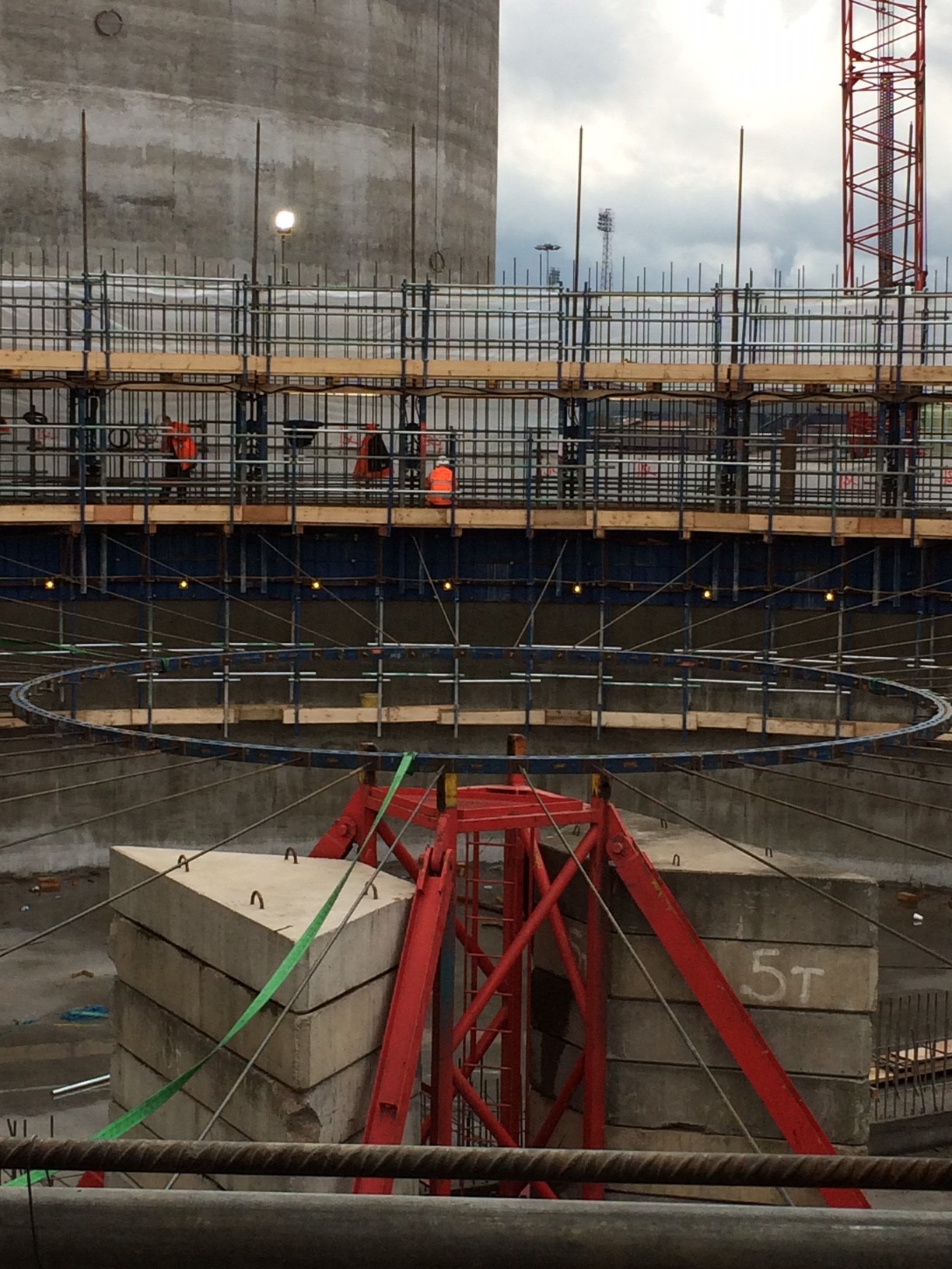
Slipform central ring.
The internal shuttering is held in position using a central ring with a number of post tensioned spokes running out to the shuttering itself. The internal shuttering in turn holds the external shuttering in place at the 450mm width required. The jacking bars that are placed internally into the wall, that allow the slipping equipment to raise up, are where the heights are transferred to allow the engineers to control the move.
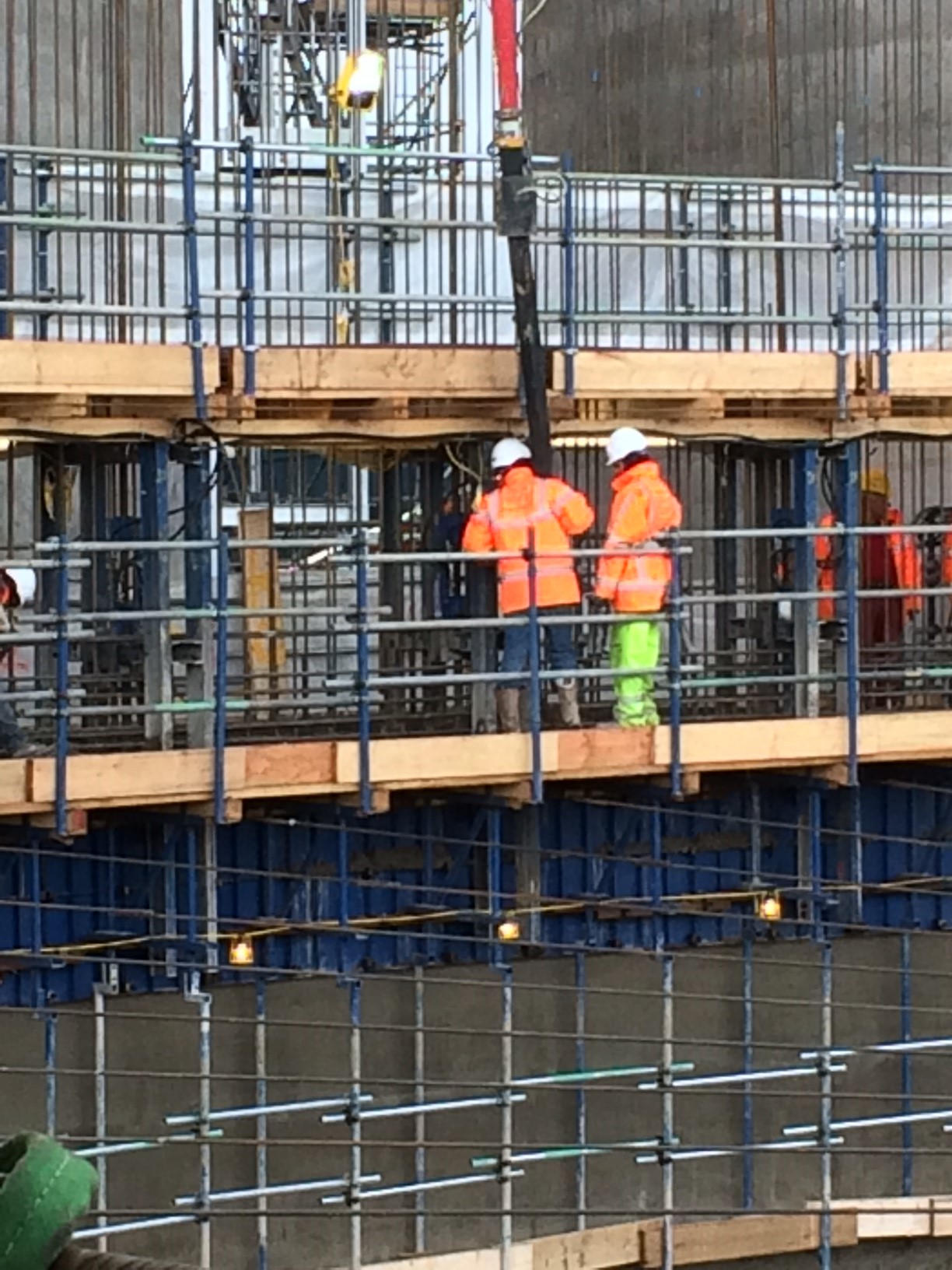
Level 2.
The concrete used is a rapid setting specification and one of the main reasons the first slip was completed so quickly was due to the high ambient temperatures seen during that first week in October. As the shuttering was 1.2m deep and the teams were slipping at around 300mm an hour the concrete was reaching sufficient strength to be slipped out of the shuttering within 3hours. The concrete strength is tested in a highly technical manner prior to it being slipped out of the shuttering. A 1.2m piece of rebar is pushed into the concrete until it will go no further, if 300mm was left protruding the equipment would slip 300mm. The bar would dictate the amount of slip. The entire structure was completed with the concrete placed on day one having only just reached its 7 day strength when the structure was completed. I have not seen the 7 day cube results yet.
The silos were tendered on a fixed price contract based around a 10 day completion per slip. The concrete sub-contractors, IFL, completed the first slip 3 days ahead of the priced schedule and its estimated that the wages alone amount to £10000 a day. Therefore the subcontractor has made at least a £30000 saving on wages during the first slip. However it may not all be profit as 13 of IFL’s workforce were arrested coming into the port for their Saturday nightshift by Immigration Officers. The Indian gentlemen may not be returning in a hurry and IFL may have to reinvest their profits into the Homeoffice to pay the fines. We’ll wait and see but I’m not convinced they care as another mini bus full of replacement Indian labourers turned up on the Sunday morning! Either way the concrete foreman is currently running on redbull and pro-plus to ensure that the 3 remaining silos are completed ahead of schedule to guarantee his substantial Christmas bonus.
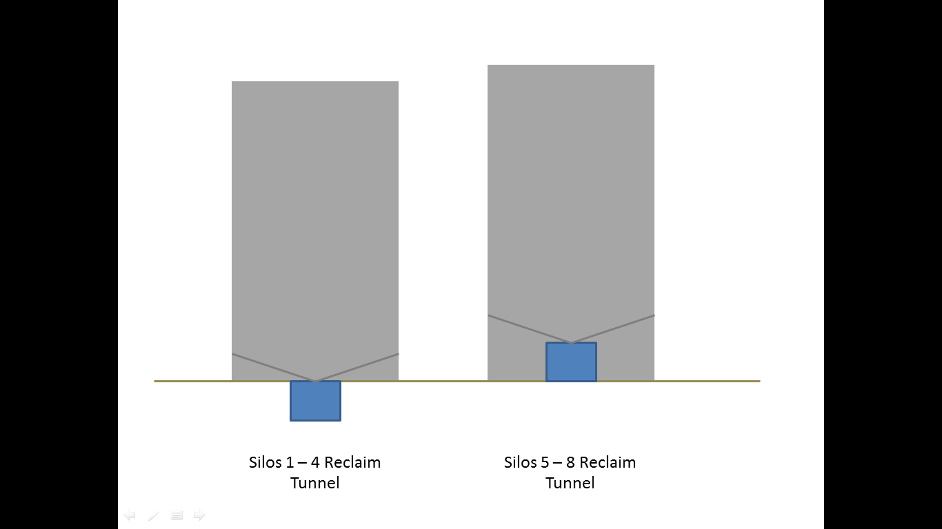
Silo Reclaim Tunnel Re-design.
As an aside, the original silos underwent a fairly detailed cost analysis to verify a proposed design change for the latest ones, that would mitigate the risks in the ground. The reclaim tunnel that runs underneath the existing silos was placed inside the new ones. Essentially the cost of the additional silo height required to maintain the capacity and extra fill for placement of the vibro-panel floors was less than the ground works associated with the excavation of the tunnel and the post construction dewatering maintenance costs. It also reduces the risk for Graham. There are only 3 access voids left in the silo walls during the slip. 2 for the new tunnel positions and one higher up for the back fill of stone, concrete flooring and vibropanels. These limited voids, go some way to explaining the speed at which the silos have been constructed when compared to Rich’s tower block.
I have spent some time working on the slip to get some additional experience but its generally a stressful area that is best avoided, especially in poor weather conditions. It wont be much fun up there with the dregs of Hurricane Gonzalo expected tomorrow.
What’s wrong with this concrete?
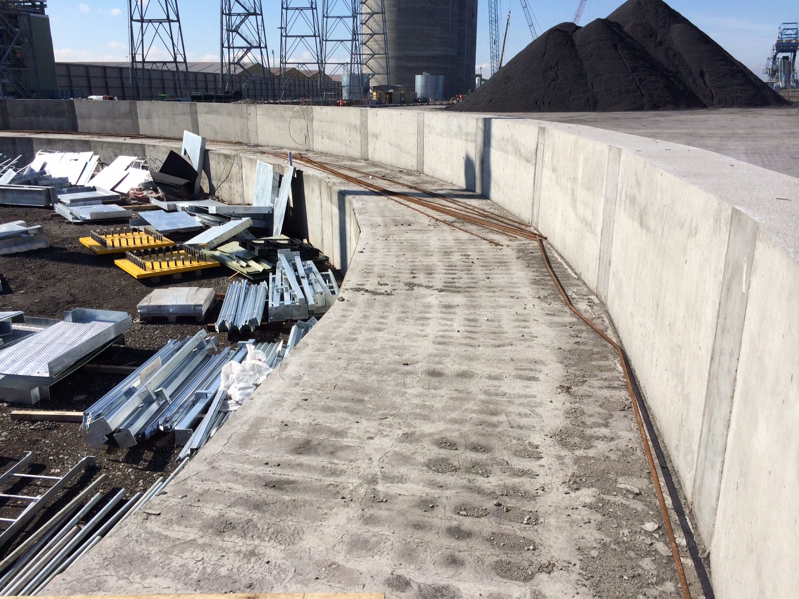
A RC beam for a radial arm coal stacker was recently completed on site as part of a £2M variation order to the original contract. The beam effectively supports a radial arm connected to a conveyor that will distribute coal evenly onto the newly created coal yard slab.
Radial beam for coal yard stacking arm.
The stepped design allows the radial arm to move laterally and distribute the coal. The top concrete surface on the main running section of the radial beam has a series of small cracks tracing the position of the rebar and depressions inbetween as seen in the following photos.
Radial beam top surface.
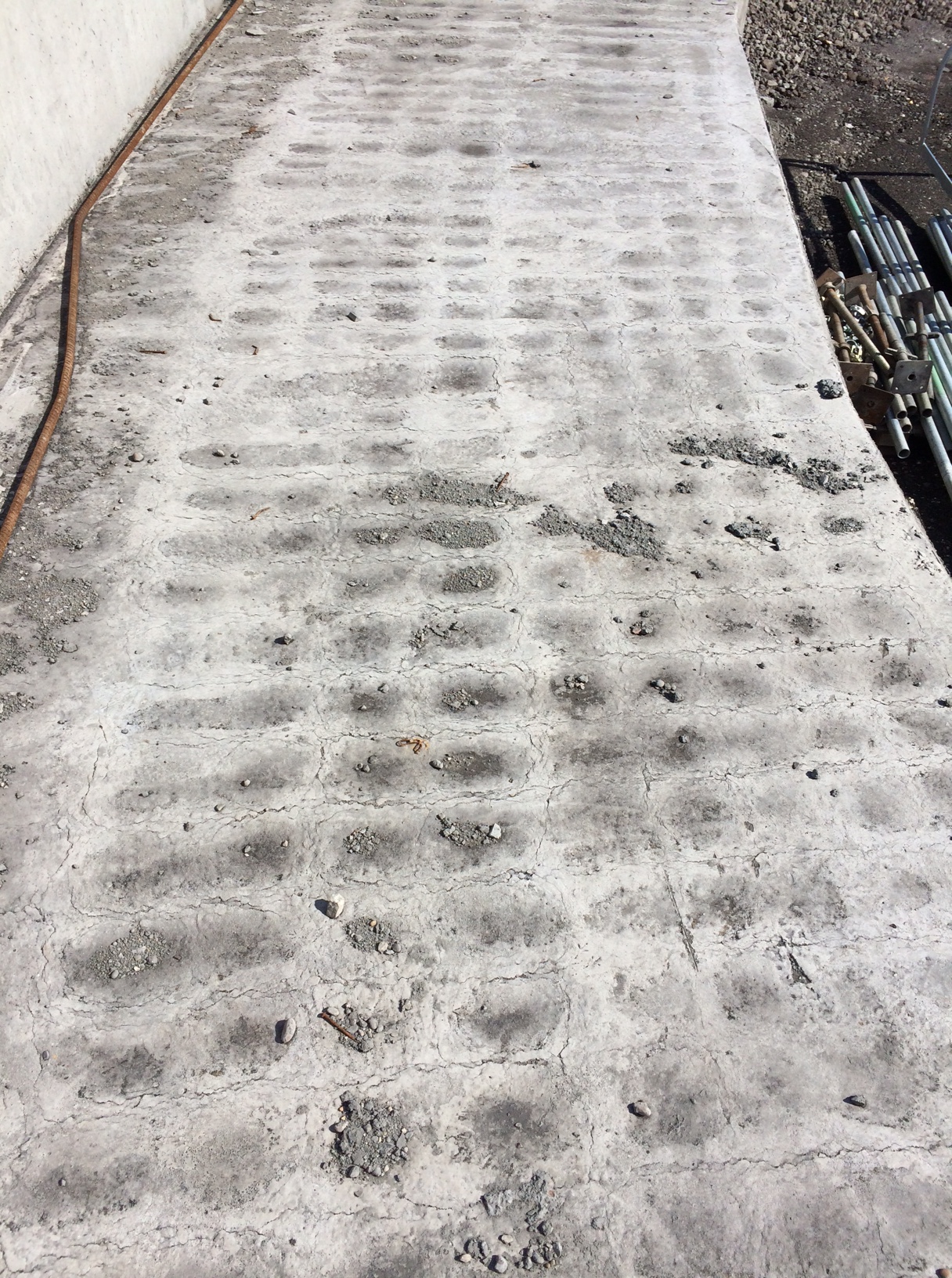
Radial beam top surface in detail.
This has occurred previously across the site (although not as severe) and seems to happen when there is a large volume of concrete poured into reasonably congested rebar.
My initial assumption was that the vertical cover was insufficient (specified 50mm) and the top reinforcement was too close to the surface of the concrete. However I saw the cover being checked prior to the pour and know that it was closer to 60mm than 50mm in most areas.
My next hypothesis was that the concrete was over vibrated creating the problem of segregation where the denser aggregates settle to the bottom while the lighter cement paste tends to move upwards allowing the lattice pattern of the rebar to be seen. This would be further accentuated by the practice of wetting up the concrete pre-pour as I have highlighted on previous blogs.
After further thought and reflection after watching the pour I had another theory and have put together a couple of slides to try and explain what I thought was happening. My theory had been that due to the depth of the pour (>2m) concrete was hardening on the top layer of reinforcing bar as it was splashed over it by the pump during the initial stages of the pour. If this was not cleared away it would create an area of hardened concrete above the top rebar that would eventually be covered during the final stages of the pour. As the concrete shrinks during the curing process it would arch over these small triangles of hardened concrete on top of the rebar, creating a surface tension and the eventual cracking and apparent depressions in-between the rebar. I know this was the case in certain areas as I spoke to the engineer in charge and he had to instructed the concreters mid pour to start cleaning off the top rebar as the pour continued due to bad practice from the sub-contractor.
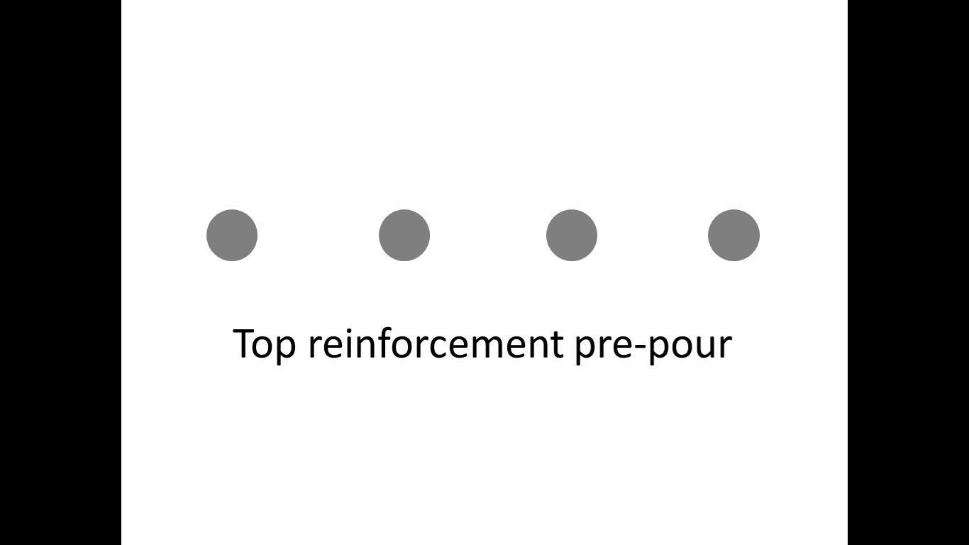
Stage 1.
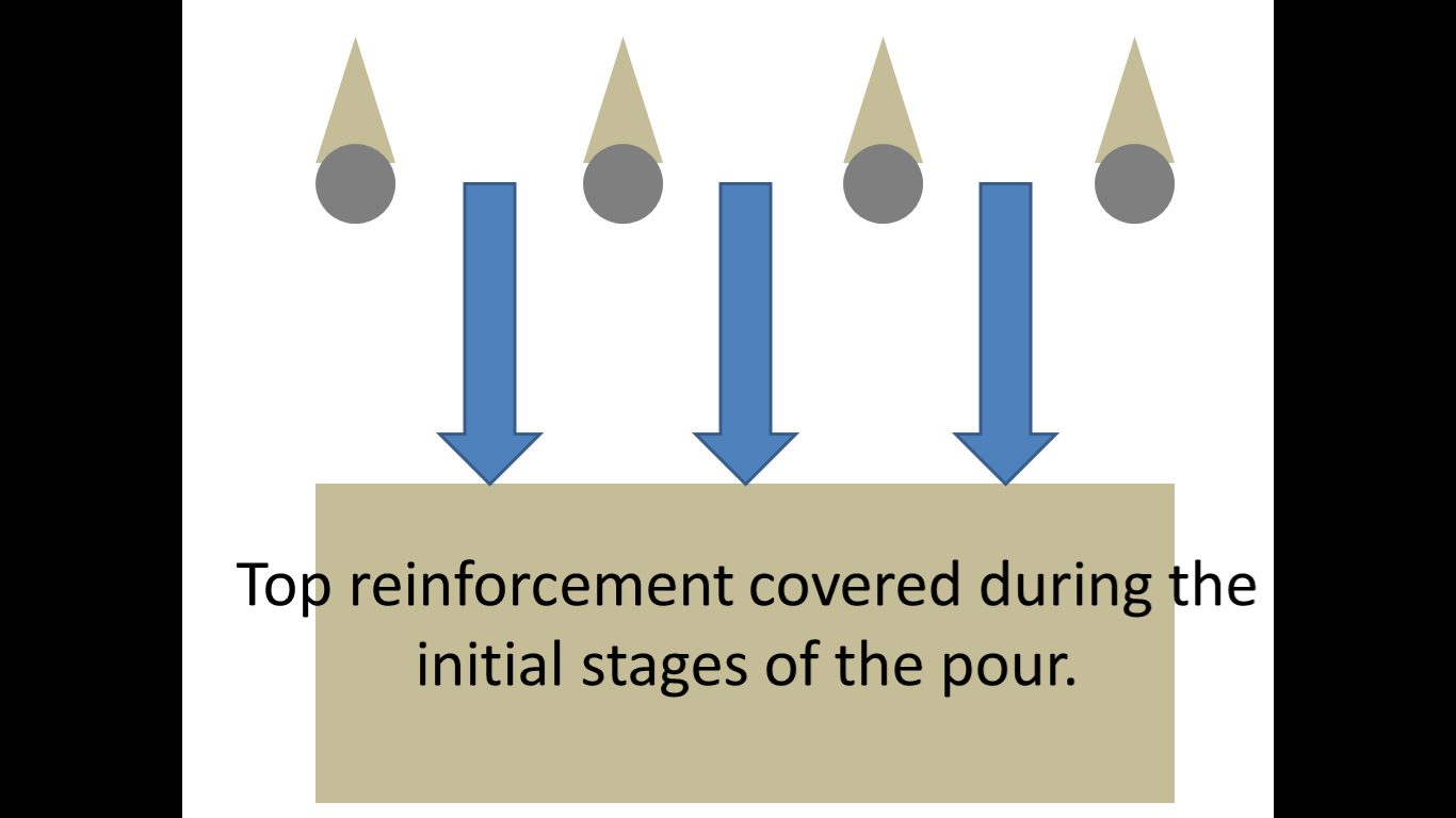
Stage 2.
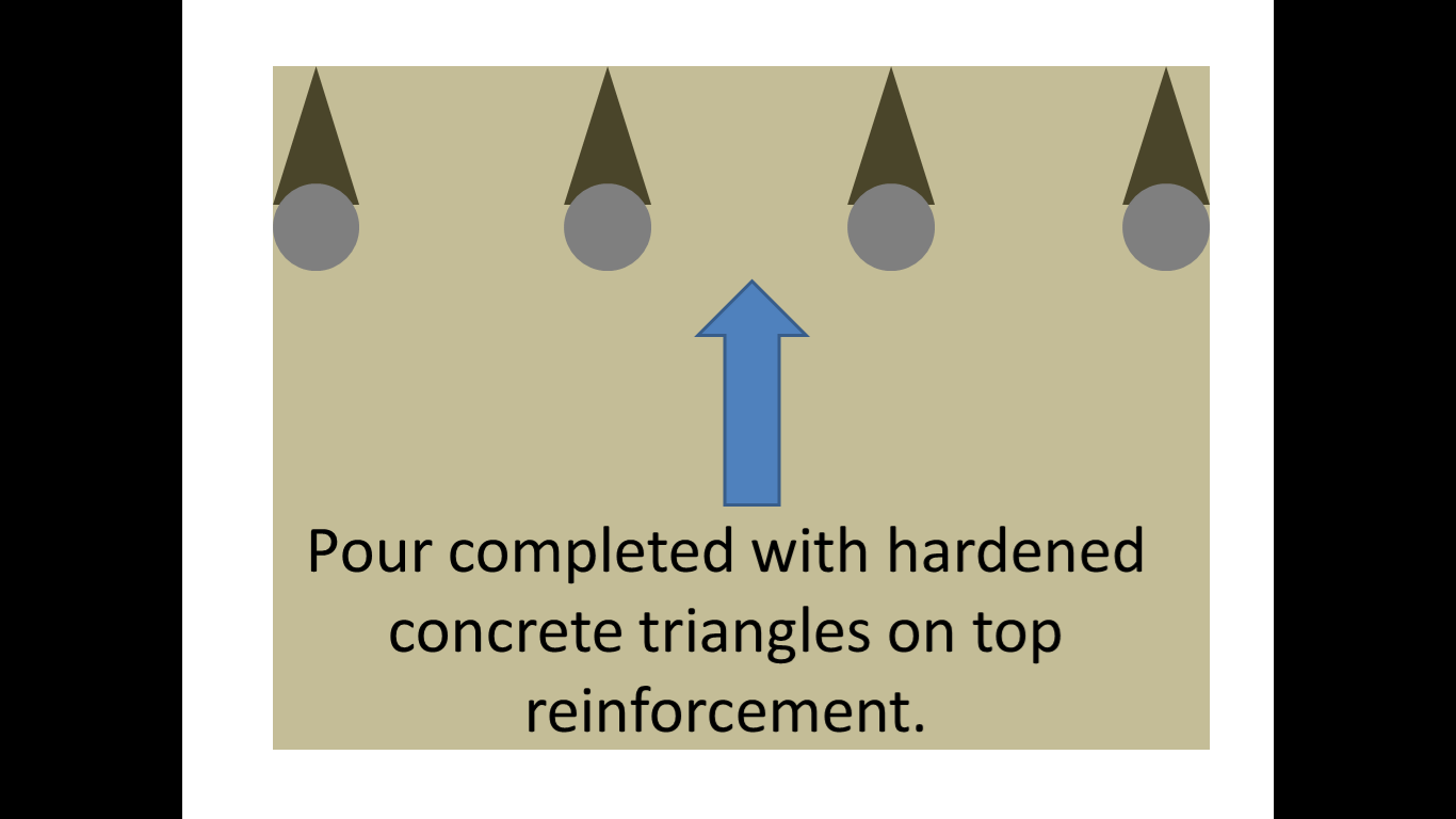
Stage 3.
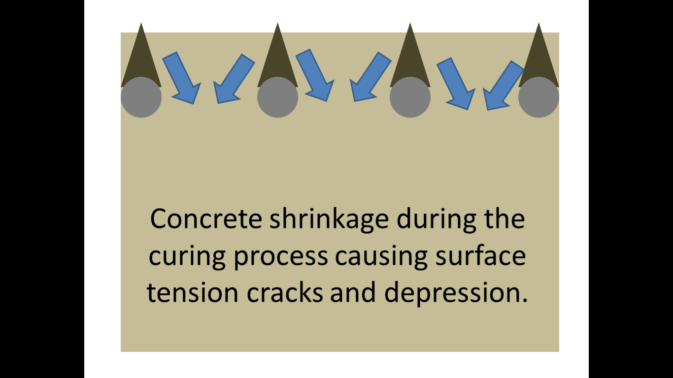
Stage 4.
However I have done some more detailed research and believe that the problem may be plastic settlement cracking. I found the following diagram on the concrete society website.
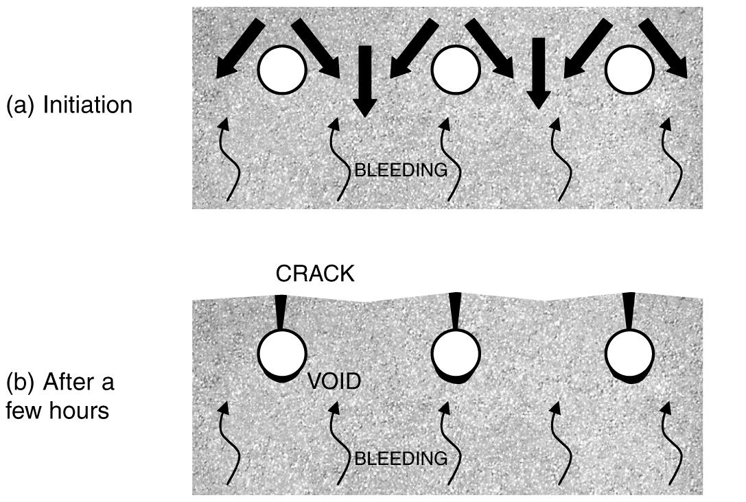
Plastic settlement cracking.
This suggests that the cracks could be caused when the settlement of fresh concrete is restrained by the reinforcement. Plastic settlement cracks can form in young concrete, within the first few hours after placing. As water moves upward through the mixture, the denser constituents move downward accentuated by any over-vibration. This downward movement may be obstructed by the top layer of reinforcement.
The plastic concrete may arch over the top of individual reinforcing bars, bringing the surface into tension. Cracks may develop at regular spacing and usually follow the line of the uppermost bars, giving a series of parallel cracks; there may also be shorter cracks at right angles over the bars running in the opposite direction as seen on the radial beam.
It is sometimes possible for plastic settlement cracks to form on a vertical face where reinforcement has restricted the free flow of concrete within the formwork. In such cases it is possible that the cracks are formed between the lines of the reinforcement.
The concrete can also be supported by the shuttering, causing restraint to the concrete in connected members. This typically happens at mushroom-heads on columns but can also occur at other locations, such as under spacer blocks. Cracks at mushroom heads of columns are generally horizontal. They are also typically 1 mm wide and can cross the full section.
So in conclusion I now believe that a combination of these factors have led to the formation of the cracks.
The radial beam was made up of large (22mm) diameter rebar along the top layer and was reasonably congested (top rebar and links at approx. 150mm spacing). The C32/40 concrete is made using 20mm aggregate and has a slump of consistence S3 100-150mm for use with the pump but is often wetted up even more prior to pouring. The concrete was pumped into place and there was no doubt that some was left on the top rebar due to splashing over it and not cleaned off. It would all be furthered by the tendency to over vibrate during the pour due to the volume.
So what’s the remedial action?
I believe the client is currently unaware of the finish as the beam has been completed well ahead of schedule. This means that remedial action can take place. It is likely that the top layer will be removed by high pressure water (hydro-blasting) down to the top layer of rebar before the surface is re-applied and finished correctly. Contractually I am unsure of where the liability currently lies, I suspect with the concrete subcontractor but I will try and dig into the subcontract to find out.
Why am I concerned?
The reason I have investigated this particular issue, that is outside of my section and responsibility, is 2-fold. Firstly it has happened on site before, including the previous sub-station ground slab and although it was not as severe when I enquired as to why it was occurring, no-one offered a solution.
Secondly, and most importantly, as I am likely to be building a significantly larger substation I do not want the same to happen to the slab I will be required to pour. Therefore any mitigation measures I can take during the pour will hopefully limit my blushes.
So what’s the preventative action?
The tendency for plastic settlement cracks to form may be reduced by adjusting the concrete mix, for example by avoiding gap-graded fine aggregate and reducing the water content, and by appropriate workmanship and control of vibration. Particular care will be required for tall elements especially the 2m+ concrete cable pits required in the sub-station base. In some cases, plastic settlement cracks can be eliminated, rather than prevented, by careful re-vibration of the concrete after they have formed. However, it is important to ensure that the concrete is not over-vibrated as may have been the case in the radial beam.
Are my conclusions correct? Thoughts???
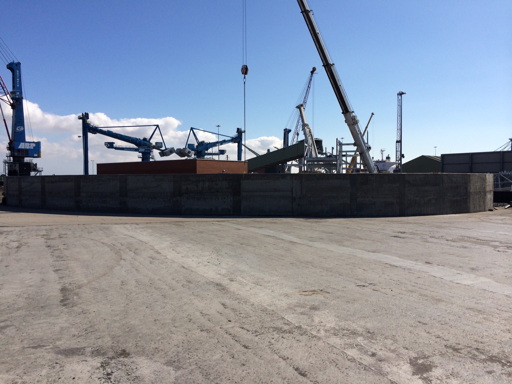
Another Big Lift
This blog will not add any value by recording reflections but it is one I thought might be reasonably interesting given Peter’s enthusiastic reaction to my last big lift photo in blog 7, DO heaven.
This is one of two 600T £7M Siwertell Container Ship Unloader’s (CSU’s) designed in Sweden, constructed in Italy and delivered to Immingham last week, being lifted off the transport ship by the two on-board 400T cranes. The whole operation went well and the ship off loaded the 2 systems and all ancillary parts in 3 days before departing a day ahead of schedule to Amsterdam (who wouldn’t?!).
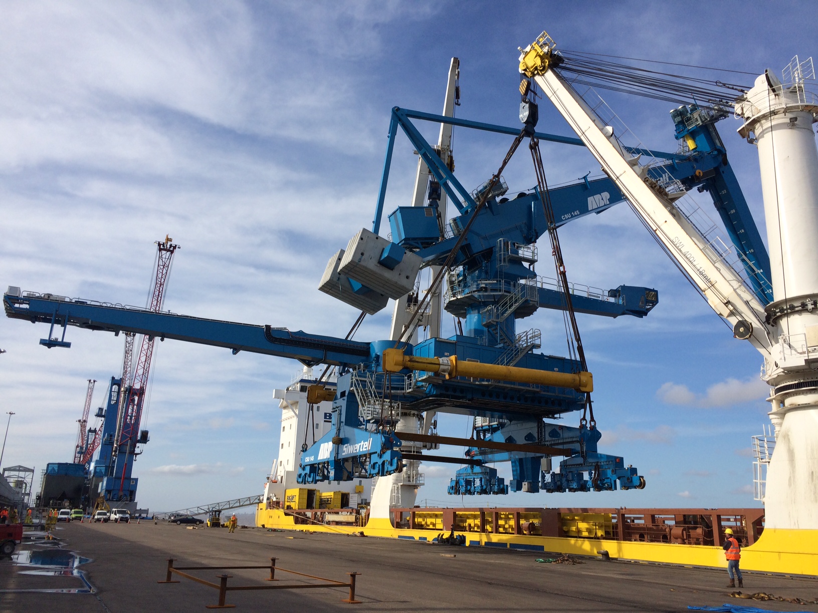
CSU No 1 is lifted from the hold.
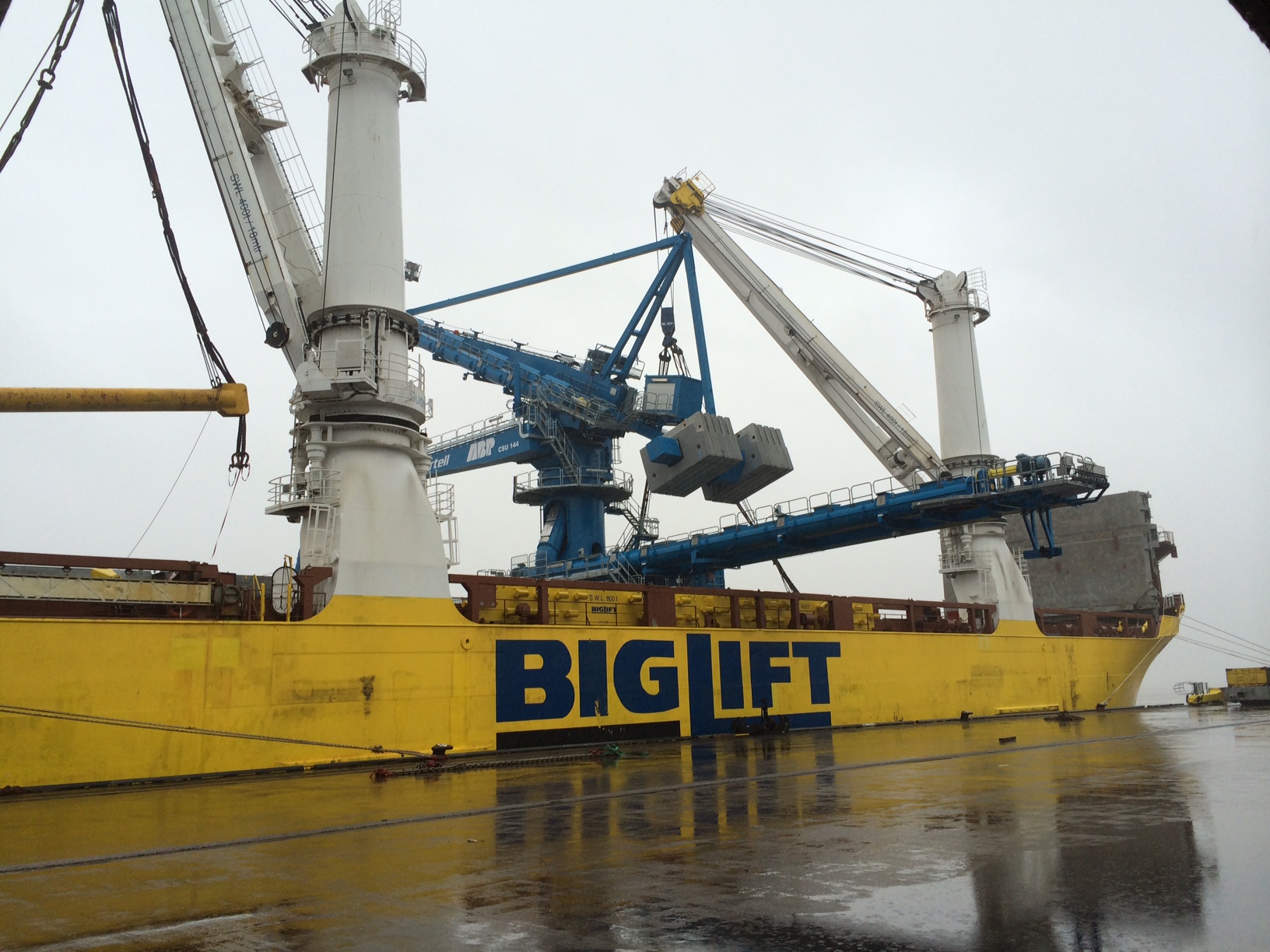
CSU No 2 is prepared for lifting.
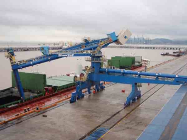
These are quite interesting pieces of engineering and are based on the Archimedes Screw principle designed in the 3rd century BC. The rail mounted screw conveyor is an Archimedes screw contained within a tube and turned by a motor so as to deliver the biomass wood pellets from the ships hold to the conveyor system leading to the RC storage silos. This dramatically reduces the amount of labour, energy, spillage, explosive dust and importantly discharge time when compared to the conventional cranes. Whilst initially expensive the discharge time is effectively halved meaning double the amount of biomass ships can be unloaded in a given time increasing ABP’s profit. I expect that they will pay for themselves in a reasonably short space of time. Whilst the image below from Siwertells website is not the greatest quality it shows exactly how the system works.
Due to my discoveries during the trail hole excavations at the sub-station there has been a delay whilst the redesign takes place and thus the CSUs have become my focus for the last week or so. This has involved a number of snagging type tasks from clearance and inspections of the rail lines that the CSUs will travel on through to the positioning, drilling and placing of the storm locks and rail clamps that guide the CSU and secure them during a North Sea battering.
HV Cable Strike!!
If you want to see a pained expression worse than Ryan’s when he realises the last chocolate digestive has been taken, walk into your offices and utter the words ‘we’ve had a HV cable strike!’
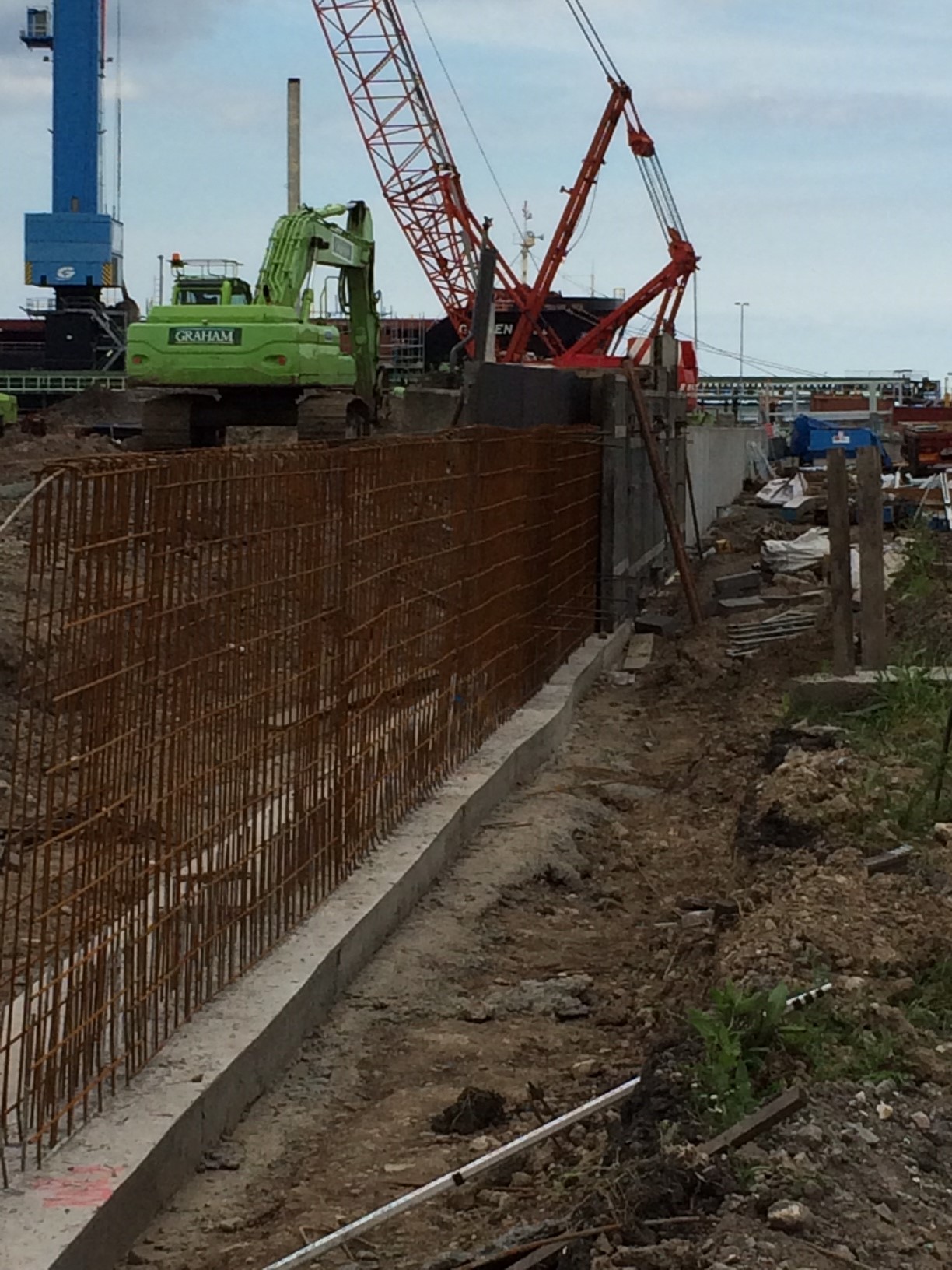
My last blog commented on the progress I was making towards my DO’s with work on the Dwarf Wall, HV ducting and student mentoring. I have completed 192.652m of the 619.310m Dwarf Wall, which is as far as I will now take it. This is no bad thing as I got as much experience out of it as was likely. The student has fledged and flown the nest to start work on the second rail load out silo for IRFT 2.
The HV ducting and deluge main proved more challenging than it first appeared and there were a whole host of learning points from the experience.
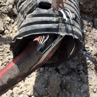
As part of the preparation for the work I organised a GPR survey to identify all the existing ABP services crossing the area we would be excavating through. This all formed part of the various permits and RAMS I completed, as mentioned in my previous blog and in detail for AER2. We successfully undermined 5 sets of existing HV lines at various points, a number of live water mains and several fibre optic telecommunication cables without incident. On the last HV cable crossing this happened:
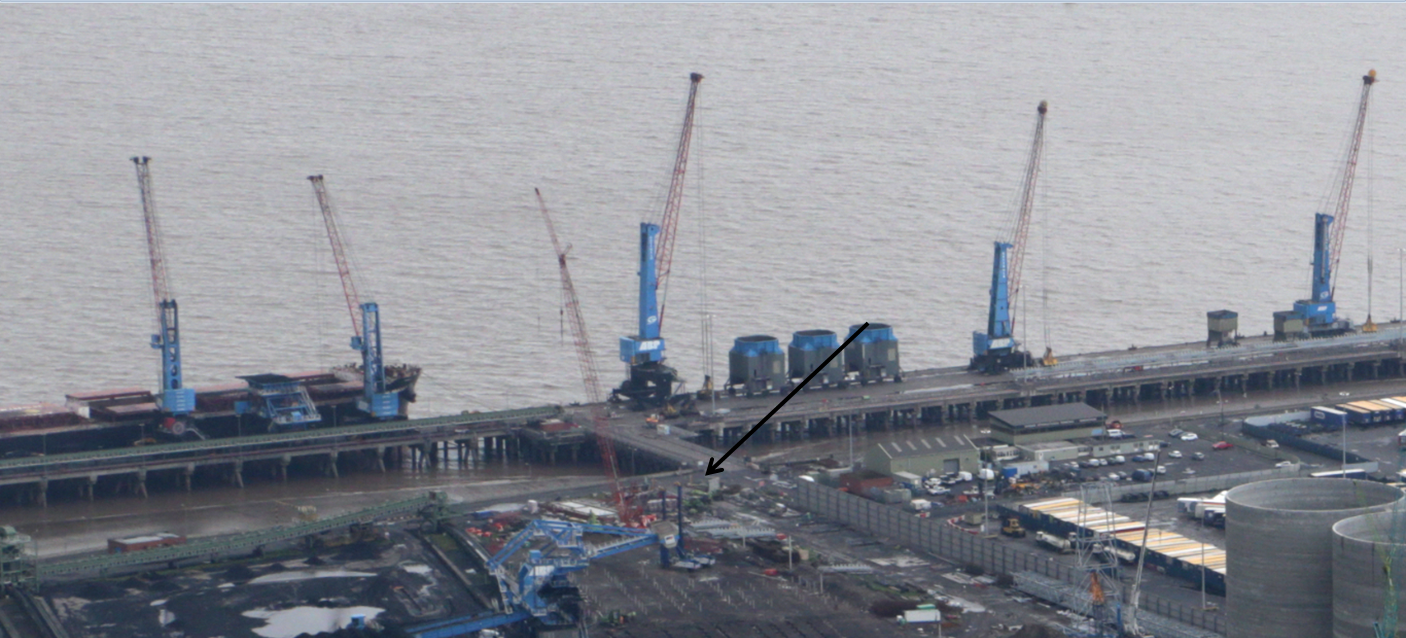
Unfortunately it was the primary HV line to the main unloading jetty (location shown in photo below), powering all the infrastructure including the cranes, where 2 container ships were being unloaded at the time. It was also during the crossing of the main access road to that jetty that we were only allowed access to for one 12 hour period. Balls.
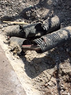
The first photo shows the primary 11kV line that we hit and the fibre optic cables that ran in parallel. There happened to be a secondary HV line directly underneath the primary that subsequently proved useful. By the skin of our teeth only the armour surround to the cable had been pierced not the inner cable and it never went bang despite being wrenched a few inches up by the excavator bucket.
So what happened??
This was my section of works but in the greatest tradition of every troop commanders favourite sapper, I wasn’t there at the time boss! The previous night I had issued the permit to dig, briefed the team (including the engineer who would cover for me in the morning) and prepared the road closure procedures for the following day. The route of all the cabling was identified through the GPR drawings, checked with a CAT scan and sprayed in red onto the road. The following morning the team set to work and the road tarmac was cut using the road cutting saw.
This is where a small series of errors came together resulting in the strike.
The road cutting saw creates a lot of dust that when suppressed by the accompanying water unit covers everything around it in a thick slurry, including red spray paint marking routes of HV lines.
The team that I had briefed the night before got pulled onto another task early on in the works (operator availability as ever) and the replacement crew, despite having also attended the evening brief, were not given a thorough HOTO or up-to-date brief by the engineer or foreman. The tarmac line that had been cut was assumed to be the line of excavation to the full depth of the ducting, as the red spray was no longer visible they just cracked on and dug away.
The engineer left in charge hadn’t noticed the red spray was no longer visible, assumed everyone had understood the brief as well as himself and was taking photos of a manhole to one side when the incident occurred.
The foreman working on the task had only arrived on site the day before, had been briefed but wasn’t really ‘acclimatised’.
I’m sure you’ll all say ‘yeah yeah’ but my timing couldn’t have been worse as I walked into the works area to hear the foreman shout ‘whoa, whoa, whoa, that doesn’t look too good …….ah Joe you’re here……take a look at this…..’!
So what did I do??
After calming down and realising nothing had gone bang, nobody had been BBQ’d, (thanks Harry for those inspiring HV strike H&S videos), and everything on the jetty was still working, I basically conducted a 4C’s operation! Train hard fight easy and all that.
I phoned my section manager (who thought I was joking) and informed the on-site health and safety advisor.
I soon had a battlefield tour on my hands as every man and his dog came down for a nosey and a photo.
Everyone was fairly pragmatic about the situation, some more so than others and I had to laugh when the foreman suggested poking it back into the ground and covering it in concrete before the client found out!
The main HV line serviced the whole jetty, the secondary line powered just the cranes and ancillary equipment ie the vital unloading equipment. After much discussion it was decided that the power would be switch to the secondary line for 2 hours so the primary could be inspected but allowing the unloading of the ships that were docked to continue. Once complete the main line was switched back on and a cordon was put into place until the ships had been completely unloaded. This then gave us a 12hr window, between the high tides, a couple of days later to get it fixed prior to the next ships arriving. The damages for a ship in port not being unloaded are huge, so realistically that was the only choice.
So what I have learnt?
Technically.
GPR Survey. The investment in a GPR survey is worth every penny and I cant recommend it highly enough in similar circumstances. The amount it reduces the risk alone is worth the investment. The cable we hit, we knew the location of, which makes it even the more frustrating. The CAT & Genny is very good for identifying services but proves difficult on our site due to the industrial nature of the fill that makes up the top 5-7m of ground as it is full of metal and old cabling. In addition the clients existing service drawings, that formed part of the initial tender, are woefully out of date and hugely inaccurate and some of the electrical cables service night time facilities so the CAT SCAN may miss them in the day, the GPR survey will not. The GPR survey allowed us to identify the services and then we could use the CAT SCAN to confirm the locations as it much easier to use on this site once you know the path of the service. I was also surprised with the accuracy of the GPR depth estimations as 90% of the time they were spot on. This has led to my insistence on getting the same done over my new site for the substation build I will be conducting, as there are a number of services including HV around the existing substation that mine will replace. I suppose the ground is a risk whatever way you look at it!
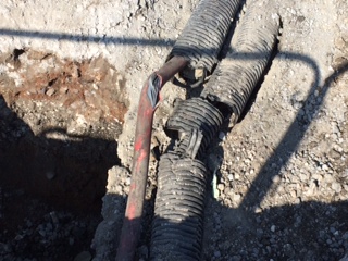
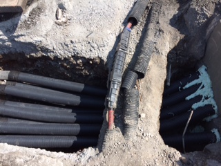
How to fix HV lines! The armour was cut away and replaced followed by a mould that was pumped full of resin to reinstate the outer casing. This was then re-sleeved with the ducting. We also used the 12 hour period to complete the undermining of the lines and fit our 12 ducts into the manhole as can all be seen in the photographs below.

Managerially.
Health and Safety. Don’t skimp on the paperwork. The H&S advisor rightly conducted an investigation and after his initial enthusiasm to hang someone was dampened, he used the opportunity as a lessons learnt scenario. He concluded that the paperwork was actually to a standard that he had rarely seen on the site! The RAMS, drawings and permits to dig I completed were comprehensive, up-to-date and everyone had been fully signed up so my arse was covered. I even suggested an additional measure that has now been adopted on site similar to the sign off sheets seen in the military when a memorandum is circulated to ensure everyone has read and understood the permit to dig. Up to that point everyone had to read and sign the RAMS but only the operator and banksman had to sign the permit to dig that contained the up-to-date drawings and service details.
Communication. Absolutely key. It was clear that much of the error had come from the change-over of the plant operator and banksman and the lack of communication between the team largely assembled in the morning. There were various levels of information amongst the team and everyone assumed everyone else knew what was going on. The lack of communication invariably led to the strike and was the main learning point from the H&S investigation.
Control. I wasn’t on the site at the time of the incident (have I mentioned that?!). I had handed over to another engineer the night before who knew of the HV line (I had sprayed it out with him) but he had been taking photos of the manholes we had constructed the day before when the incident happened. If I had been there I would like to think that I would have been more resistant to the change of plant operator and at least stopped the incident as I had lived and breathed those services for the preceding weeks. I was a little disappointed with the whole episode from a personal perspective as we had conducted a number of crossings to this previously without incident, and we stumbled at the last fence.
I have now completed my summer leave and have started setting up my own mini-site for the sub-station construction I have been given the independent command of. The design is yet to be completely finalised but this week I have cracked on conducted the GPR survey (as mentioned above) the CAT SCAN and dug a number of trail holes to confirm the services. I am taking the design co-ordinator down to the site this afternoon as a number of my discoveries (railway lines, CFA piles, pile caps, sheet piles etc) are likely to force additional redesign – watch this space.
It’s DO heaven.
The project has evolved in recent weeks with several variation orders taking the total value of the work from £63m to £121.5m. These additions include £6.5m worth of variations to the initial contract covering a number of smaller embellishments and alterations, £2.5 for a RC slab in the coal yard adjacent to the site, £2m for a radial arm stacking conveyor also for the coal yard and £47m for IRFT 2. IRFT 2 is a sizeable extension to the facilities currently under construction including 4 more RC Biomass storage silos, an extension to the existing conveyor system and another rail load out facility and accompanying silo. The work on the coal yard slab and the piling for IRFT 2 has started and extends the duration of the whole contract from October 14 until July 15. Part of the site (phase 1) was commissioned on 22 May 14 and now fully operates from the lorry load in area to the rail load out facility. This allows large Biomass container ships to dock at the port, where HGVs can be loaded directly and then the pellets can be transferred to the rail load out point for onward movement to Drax power station. Part of this commissioning included testing and individually commissioning all of the electrical, safety, dust and fire suppression systems and the establishment of an operations team to run the facility. To date over 13000t of wood pellet have been loaded and transported to Drax power station. The completion date for IRFT 1 phase 2 (the rest of the site) is currently delayed by 22 working days / 30 calendar days and as such performance testing of the plant is scheduled to begin on 13 October 2014, the site is running a 12 hour day / 7 day week to maintain progress. The progress for IRFT 2 is currently on schedule with work having started on 09 June 14.
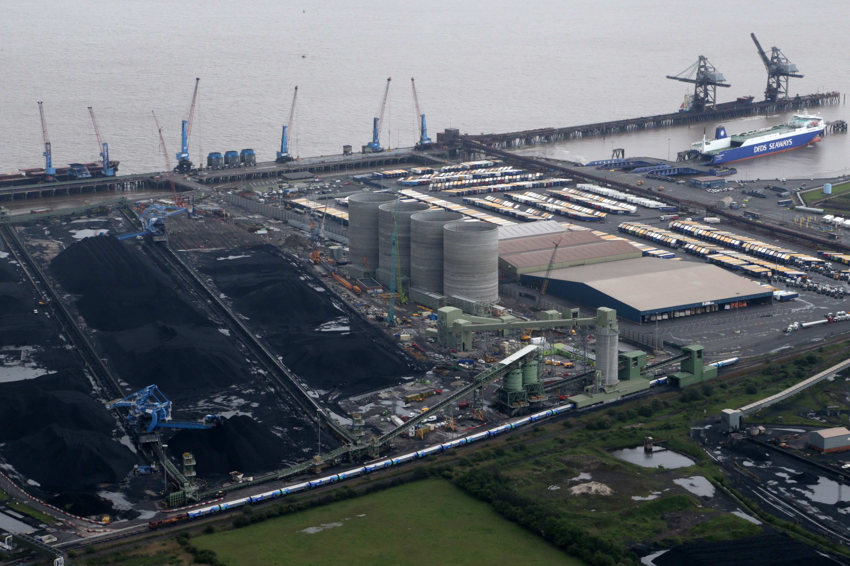
The current site.
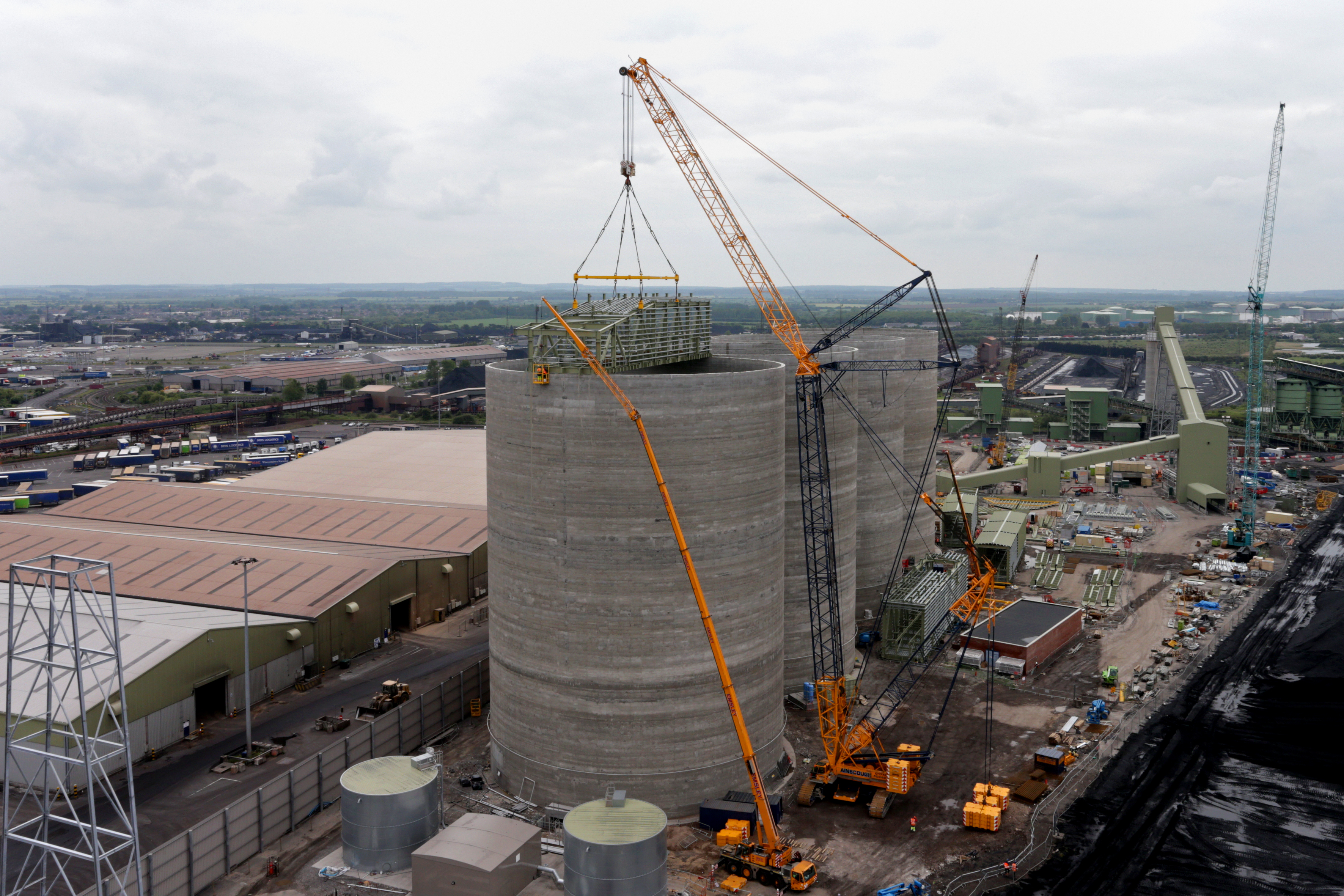
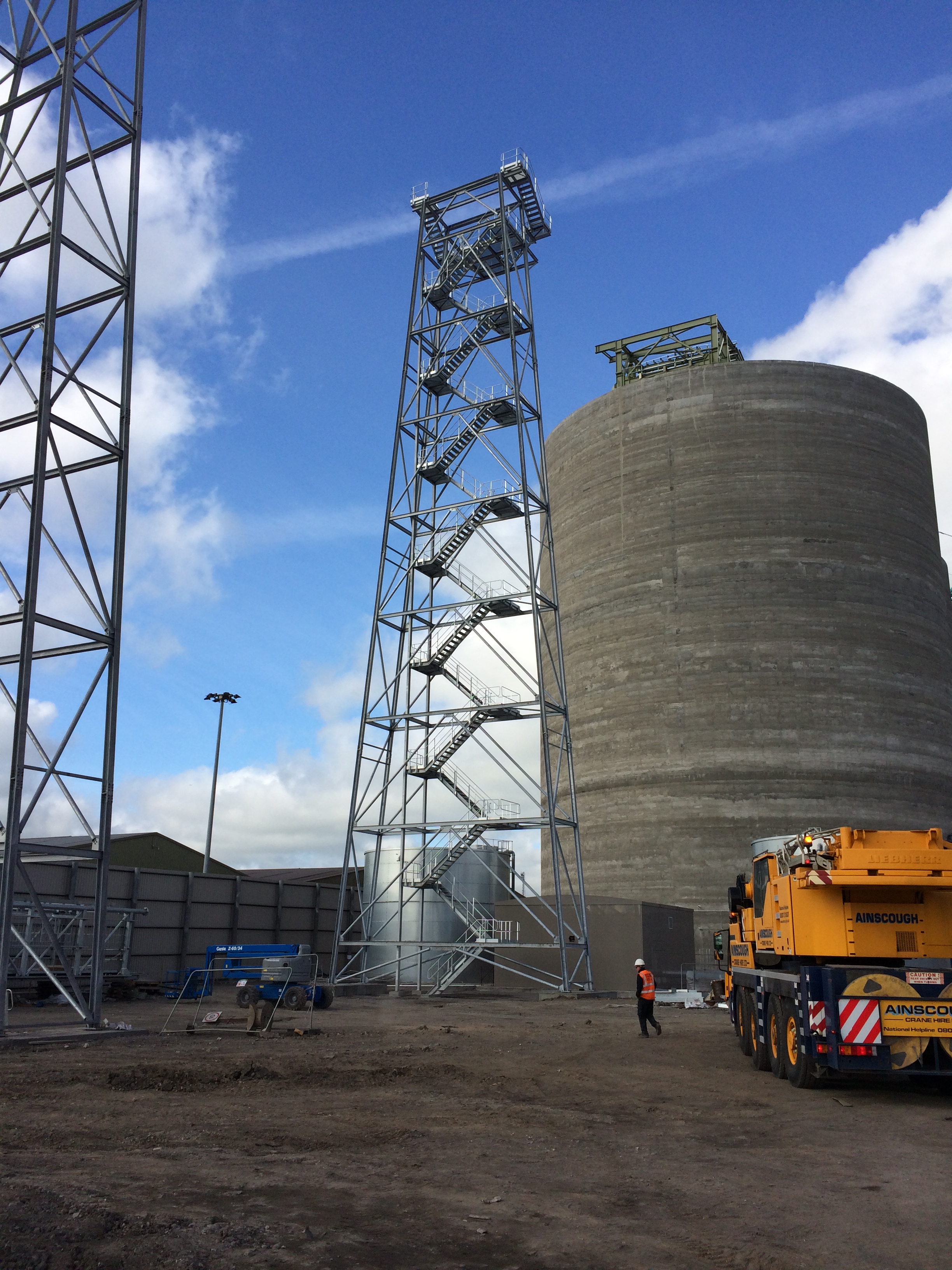
Roof truss lifted onto silo 1.
My part in this, the dwarf wall, continues although at a slower pace due to increased pours for the roof slabs to cap the IRFT 1 silos, but I now have other projects to keep me busy in my section of works.
The Dwarf Wall continues.
These additional duties are allowing me to knock off quite a few of the harder to achieve DO’s.
I am now also responsible for the excavating and placing of several 100m’s of HV ducting and a water deluge main for the fire suppression system of the previously constructed Conveyor 620 system. Whilst technically simple the mountain of paperwork I have had to complete for each section has allowed me to gain some purchase working towards the difficult DO’s. The ducting effectively runs between the various substations, old and new that border my section of works, hence the responsibility, and cross a significant number of existing live and non-live services.
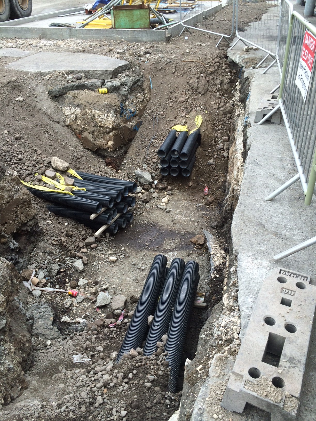
Ducting runs into a future manhole.
I have completed an overarching method statement and risk assessment for the task, breaking it down into individual sections or ducting runs between the existing and to be constructed manholes. This includes the procedures for working parallel to and crossing over existing services including live HV cables; a detailed traffic management plan due to several road closures (not popular with the client, ABP, running a very busy port) and the safety precautions for working in deep excavations.
Prior to this I had to conduct an in-depth analysis utilising all the available drawings provided by the client, utility companies and a Graham commissioned GPR survey to pinpoint all the services. I then verified these findings with a CAT Scan survey having just completed the CAT and Genny course (one for the CPD record).
I have then been briefing the subcontractors outlining the programme of works, the methodology, the risk mitigation procedures and any residual risk before getting them to sign up prior to sending all the data through to the client for their final approval.
All of this activity has allowed me to progress towards a number of DO’s (B2, C1, D1, E2).
I have also volunteered to mentor a year-long placement student who started in earnest last week. This additional responsibility has allowed me to consolidate my experiences to date and share MY extensive knowledge. I felt it necessary to step off on the right foot so I immediately grilled him for definition of undrained shear strength to gauge the depth of HIS knowledge…..there was a long pause…..an awkward shuffling of the feet…..a look to the left and the right for moral support…..and then came the McGuirk 1000yard stare…..he didn’t know, can you believe it?? I couldn’t. What are they being taught at uni these days? I gesticulated wildly, banged the desk and was about to unleash my pavlovian response when I got distracted by a chocolate digestive. I’m surprised I’m still talking to this simpleton but I’ll tough it out for now as it is proving another excellent opportunity to knock off some DO’s (C3, D1 and 2 and E4)!
I should have the ducts finished by the end of this week, the wall by the following week prior to my summer leave. On my return I am likely to be given an independent command……my own bespoke site about a mile down the road to build a sub-station all by myself! I have also requested to be part of IRFT 2 rail load out silo slip forming team to ensure that I get the maximum exposure to as many different construction processes as possible. No real reflections this time but plenty of DO progress.
Goodbye chapter 13……hello chapter 8.
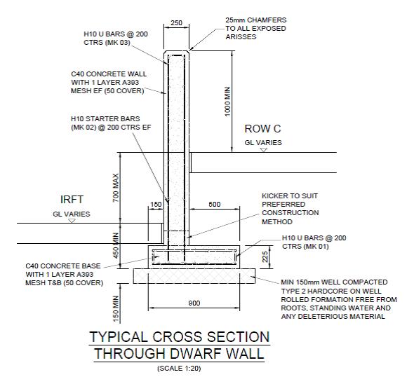
So I mentioned previously that I’m now running with the construction of a 619.310m cantilever dwarf retaining wall stretching the length of the site separating the coal storage area from the biomass handling facilities. In many ways it’s a breeze compared to the previous thrashing of the C620 foundations (hence my upsurge in blogs!) but I don’t want to tempt fate too much at this early stage.
The wall ranges in height from around 1m to over 3m with 2 distinct gradients and a varying footprint profile. The wall itself is 250mm thick, off set 500m from the edge of a 900mm long base forming a cantilever retaining wall. There are ‘Rainbirds’ positioned at regular intervals that are effectively large plinths supporting a water suppression system (to limit the dust) cast into the wall itself and contraction joints every 15m.
As it seems the assist in future discussions (thinking back to numerous piling methodology blogs) this is the construction process:
I mark out the base centre-line with the TS and off set 600mm either side allowing 100mm for a little extra space for the steel fixers to work in. Then set the height on the laser level and get the excavator in to dig to the correct level – usually about 500mm below the prepared ground surface. Compact some type 2 aggregate into the excavation and order some ST1-S3 concrete for blinding and get that in to a depth of 50mm.
I then get out the TS again and set nails in the blinding for edge of concrete at the base and the centreline of the off-set wall for the starter bars.
I’ll check the steel alignment and then order C32/40 S3 concrete and pour the 225mm base. I have been instructed not to place shuttering parallel to the direction of the wall on either side for speed and as the excavation is only 100mm extra either side the additional concrete wasted has been accepted.
As a side issue – the excavation is usually a touch bigger than 100mm either side (operator) so assume 620m of 300mm additional excavation at 225mm depth. A quick time/cost analysis of 620m of 300mm additional excavation at 225mm deep is 42m3 of wasted structural concrete at £65 a m3 = £2730. That’s 68 hours-worth of time for 2 labourers at £20 an hour to fit some reusable shuttering either side. It would take them significantly less time as it would only require single planks and minimal bracing and thus could be a small saving but I suppose it’s a drop in the ocean in the grand scheme of things. The counter argument is the time saved but I have the base slab poured at least 60m+ in advance of the much more time consuming wall construction.
Anyway, I then get out the TS again and set nails in the structural concrete base for the lines of the wall (250mm apart) and the expansion joint positions and hope that the starter bars have not moved during the base pour and appear in the correct position inside the wall makers!
The shuttering is then placed on the rear side of the wall and I use the dumpy level to put nails into the rear shuttering dictating the correct gradient for the top of the wall (1/143). This allows the joiners to place the chamfer filet. Once in place the steel fixers move in and erect the internal wall steel (just mesh) using the filet as there TOC measure to allow 50mm cover.
I then check the steel and horizontal cover prior to the front wall face shuttering being placed and second filet line positioned. Once the shuttering is complete I have been using the TS to check the top alignment of the shuttering which as long as they have used my original nails in the base and kept it vertical it has generally been within 5mm, therefore acceptable. The wall section is then poured using a 2m3 skip and crane.
The interesting issue the wall has raised is in the contraction joint detail and there has been much discussion as to what a ‘formed day joint’ (as can be seen on the picture below) entails.
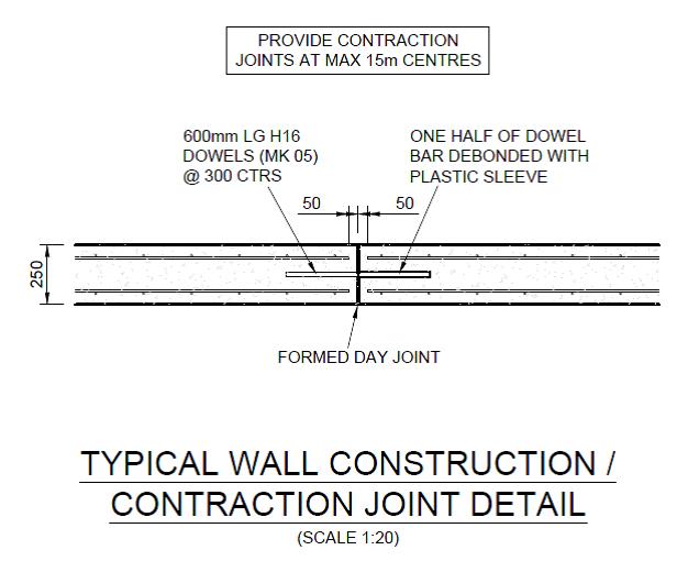
My understanding is that this is a contraction and expansion joint justified by the use of the 600mm half debonded dowels placed at 300mm centres, connecting each wall section. These are a common feature of expansion joints as the sections are tied together by these dowels but the sleeving in one of the sections allows expansion to take place without generating additional stresses within the wall. Expansion joints also feature a definitive gap between the sections to accommodate this potential movement and reduce the risk of potentially damaging forces with the structure. Clearly this gap and dowel also serve to accommodate contraction of the concrete.
To facilitate the gap of the expansion joint I have been placing 10mm sheets of flexi cell inbetween the wall sections to create the gap. These will then have 15-20mm cut away from the exposed edge and a rubber sealant will be used to waterproof the joint. The picture below shows the joint with the flexi cell prior to the sealant. This flexi cell allows contraction and expansion and increases the protection against corrosion of the steel dowels if the gap was not filled. This is the method that the joiners/fixers have used across the site for similar joints.

Questions have been asked (by other engineers) as to why I’m doing this? Their understanding of a formed day joint is simply a construction joint ie you pour up to the end of the section, allow the concrete to cure and simply pour the next section on another day from that surface. Even if a very thin divider was used to ensure clean edges this joint would surely allow only contraction and almost negligible expansion.
The GA does detail a ‘construction / contraction joint’ . A contraction joint only accommodates shrinkage so the correct procedure, by the title, is likely to not involve flexi-cell. However the use of dowel bars to accommodate contraction alone is surely a bit ‘belt and braces’ and indicates the requirement for an expansion capability?
Incidentally the concrete has contracted during the curing process, as can be seen in the flexi cell photo above. This would subsequently leave a more significant gap for future expansion if a simple construction joint was used but surely the dowel bars would be too exposed with a clear gap?
I must add that I have not been flying solo with this and checked the procedure with the MS (which mentions flexi-cell) and my line manager prior to cracking on.
Thoughts?
C620?? Done. Blog No 5.
As I mentioned in reply to my previous blog comments I am now running with the construction of a 619.310m retaining wall but before I discuss the details and issues already surrounding this wall I will conclude with a few more details on C620 and another reflection.
I will also add a few photos to the shopping list style of activities I included for Blog 4 as I now have a working phone again!
The foundation for Transfer Tower 535 (shown below) gives you an idea of the main foundation bases constructed (x3) and the type of layout of the services, deluge pipes, transfer beams, cladding upstands, gravel POL pits for the mechanical services, plinths and irregular off set bolt pads. All reasonably complex for a first timer!! The first picture below is taken from Blog 3 just after I had finished the excavation of TT535, the second picture shows the completed foundation.
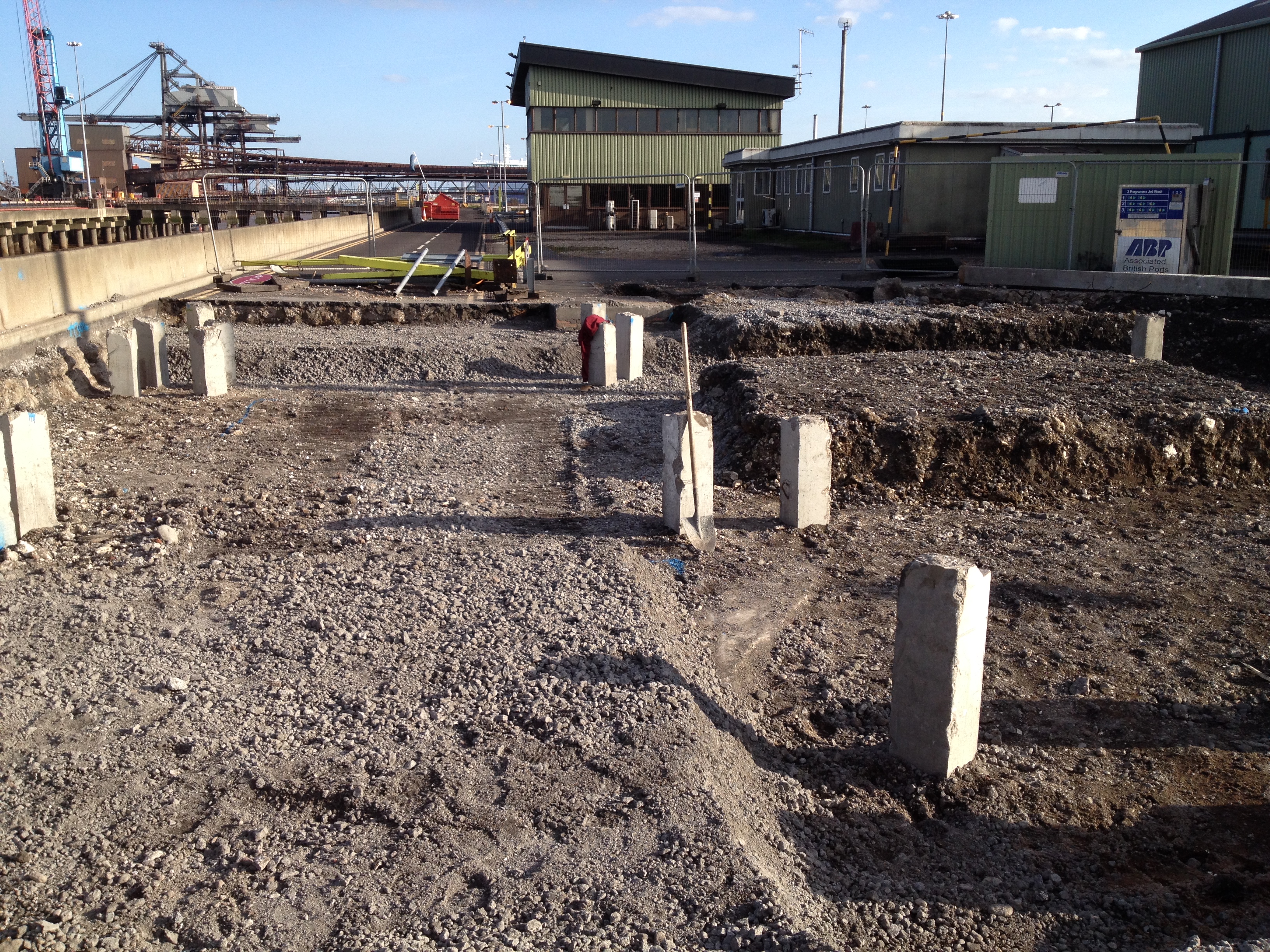

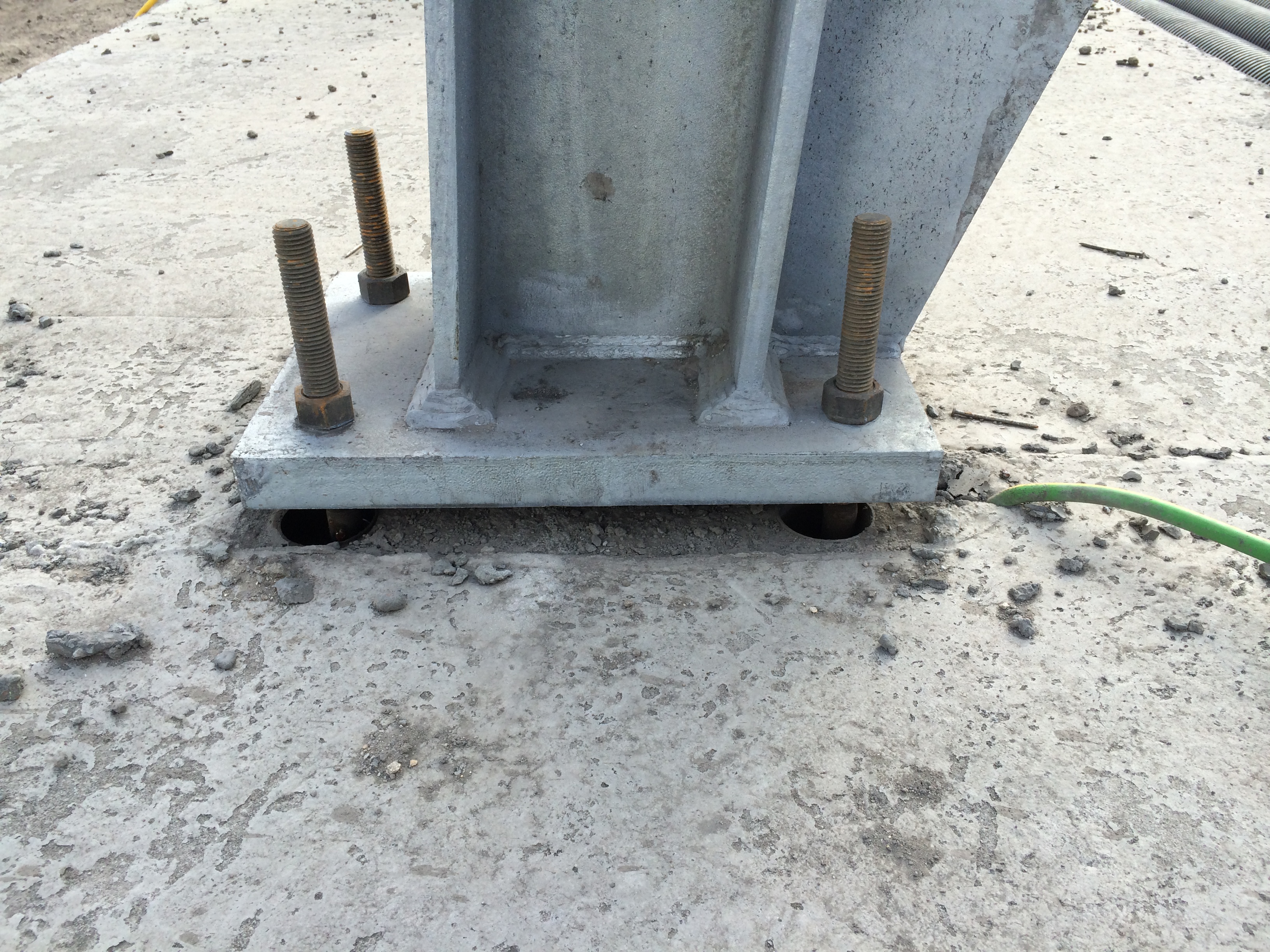
The steel trestles are now going up in earnest on the smaller trestle bases (4 of 8 to date) and they continue to fit – fingers crossed for the rest. The first photograph below shows a Trestle 10 column base plate fixed into position. The 25mm gap below the plate has been packed out and will be grouted to set the position. The photograph below that shows the exposed elements of the foundation for Trestle 10. Each slab had a deep foundation of 8 x PC RC 26m piles and housed 2 x bolt pads. They were connected by 2 parallel transfer beams running between the pads (now buried) that provided the platform for the small plinths, accompanying bolt pads and the stair beam. More importantly they reduce the risk of differential settlement across the 2 pads that the intolerant mechanical structure and services placed onto them cannot take.

Trestle 10 is now complete and is the largest of all the trestles taking the conveyor up to the top of the Biomass storage silos.
The bolt pads are made in advance and fixed into plywood templates that match the column base plate exactly. The bolts are placed into 60mm drain pipe cut to length acting as a void former to allow some horizontal movement for ease of placement and take out any setting out error. The trestle foundations were designed for compression and tension (predominately due to the wind loading on the high structures) and as such additional steel right angle plates were fixed to the ends of the bolts to increase the resistance to the tensile force. The design and finished in-place bolt pad (template removed) can be seen below.
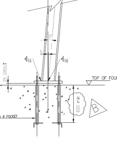
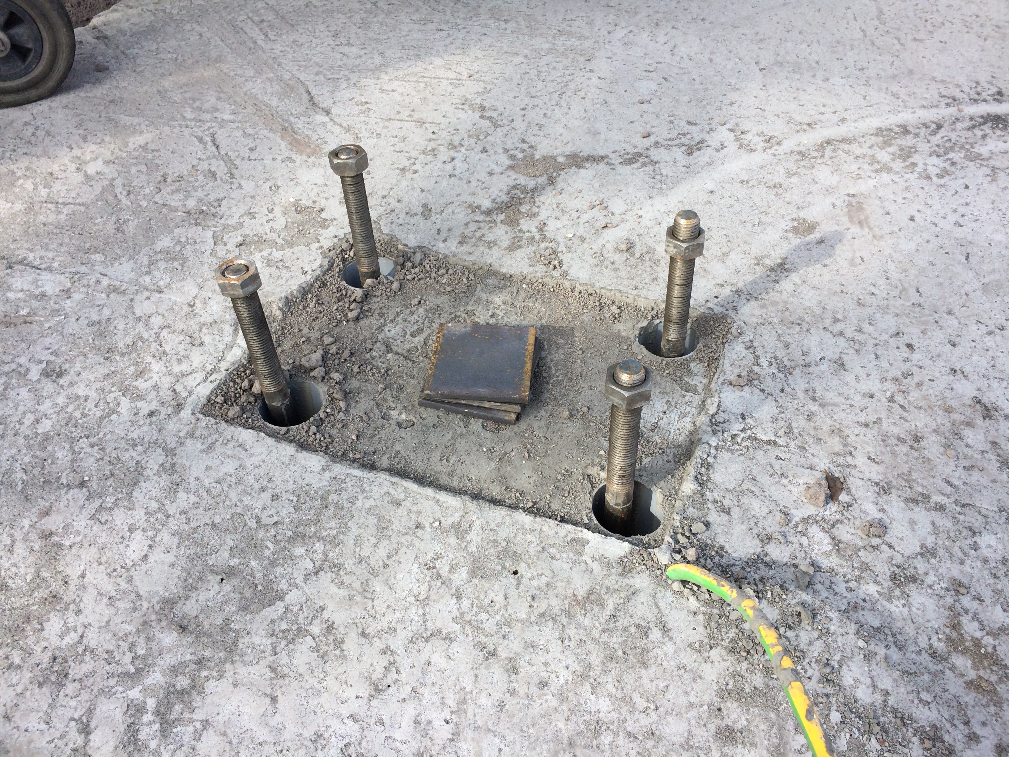
These were a pain to place as the steel cages had been pre-fabricated and lowered into place prior to the placement of the bolts and trying to attach the heavy steel right angle plates onto bolts through and 700mm deep into a 1000mm deep steel cage was tricky.
I set out the nails for the placement of the bolts, stringlines were used to set the correct position and wooden cross bracing was used to fix the pads to the correct height and location. On the first foundation featuring these plated pads we used the addition of steel tying wire to hold them into position. I quickly discovered this was not enough.
Issue. The specification for the C32/40 concrete used in the C620 foundations was for consistence class S3 and a max W/C ratio of 0.45 giving a target slump of between 100-150mm (-20mm, +30mm) and generally the team liked it at 150mm+ for ease of placement. On one of the initial pours where these particular plated bolt pads were used we had an arrival slump of 90mm which I said was acceptable, as per the guidelines, and instructed the team to begin pouring. Due to the plates on the pads and the stiffer concrete mix the bolt pads rotated and moved significantly causing me a real headache as we quickly reset the lines and used various levers and improvised methods to work them back into position. This was all to the continuous backdrop of ‘I told you it was too stiff’ from the concrete team. Thanks.
Solution. For subsequent pours I held the lorry until the slump test was conducted, used a Graham Construction slump adjustment chart to get the predicted slump to around 150mm, tested it again (if there was enough time) and poured with much greater success. In addition I insisted that steel Z bars were used to brace the bottom of the plates to the top of the steel cage and they were quickly tacked into place by the welder. This resulted in a much smoother pour and significantly less stress/abuse for me.
Reflection. The reflection from this issue was one of quality control and the difficulties surrounding it. Enforcing it has made me unpopular on a number of occasions. This site is over 18months through the project and the team of sub-contractors have been together since the start, working with LaFarge the concrete suppliers. ESG are sub contracted to conduct a slump test on all loads and 1 cube test per day or every 10 lorry loads however it has become site practice to get the cubes done every 20m3 (approx. 3-4 lorry loads). I have witnessed poor practice on a number of occasions across the site as a lorry would turn up, the slump and cubes would be taken and then the mix would be wetted up to suit the pourers and placed. On my section, to prevent this, I would have to physically stop the wagon, insist on the slump being taken, adjust the mix as required, slump test it again and then get the cubes taken. As long as I kept it within the guidelines stated above, which at the upper end was more than workable enough for the concrete team, I could not understand their reluctance to do the right thing? Quality control and assurance are vital in this a marine environment and I could only put it down to the additional time (probably no more than 10mins) it took to complete as they just want to ‘get it done’ as the subcontractor is paid per m3 of concrete poured.
There were obviously more learning points and issues that I have captured for my DO’s but having discussed responsibility, speed and accuracy, services, piling problems and solutions, more piling problems, construction methodology, ground investigation, risk, concreting and quality control I feel I can put C620 to bed for the blogs and save some final bits for AER2.
I will now start drafting a blog for another issue I already have for my retaining wall!
