Archive
Chocrete…
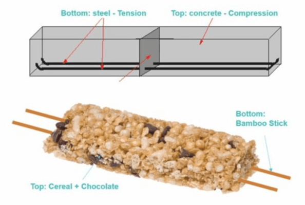
For anyone thinking of conducting STEM activities there is a good idea/article about building with chocrete on the IStructE website, link below…
https://www.istructe.org/blog/2018/building-with-chocrete
Design and implementation of seismic resistant schools in rural Nepal

Interesting article in this months issue of ‘The Structural Engineer’ on how engineers can overcome the problems between design and implementation of seismic-resistant schools in rural Nepal. It covers issues such as skilled labour/quality control, availability of materials, local politics, bureaucracy/design approval, corruption, and perception of materials. It also proposes the following recommendations:
1) Engage with local politicians. Try to win the trust of individuals in the community who can help you understand the power dynamics. This is as important a preparation as a site survey.
2) Understand the limitations of the local workforce. Even working masons struggle to
understand written plans and new methods. Consider photos and 3D constructions. Expect a diff erent work ethic from labourers, and factor in delays.
3) Source materials carefully: you may need to compromise. Consider the problems of
transportation.
4) Consider innovative materials and methods. See what has been used successfully in
the area.
5) Adapt buildings for safety, but incorporate traditional features and appearance.
6) Anticipate corruption, and devise a strategy for its management from the planning stage.
7) Liaise with and learn from NGOs already working in the area: they will have solved many of the problems you face.
8) Remain optimistic that your efforts are worthwhile, and that children will lead better and safer lives as a result.
Given the environments we may find ourselves working in the future it’s worth a read – there’s also a link in the article to a webinar for the more visual learners!
Link to article: https://www.istructe.org/journal/volumes/volume-95-(2017)/issue-11-12/complete-issue-(november-december-2017)
Those on Phase 1, if you aren’t already aware, you can get a student membership with the IStructE for free that gives you access to a lot of useful resources.
Link to student membership: https://www.istructe.org/membership/types-of-membership/student-member
Ed (or anyone else who’s worked out there) – during your time in Nepal was there much consideration given to Earthquake design? Would be interested to hear your thoughts on the article.
Backpropping puzzle
Issue. So the concrete frame sub-contractors TWD made a slight error in his backpropping calculations. Unfortunately when interrogating the structural loading document for the permanent design he forgot to subtract the selfweight of the slab and therefore overestimated the capacity of the slab in the temporary state (Figure 1).

Figure 1 – Backprop design
In the permanent design the intermediate slab is designed for a dead load of 7.4kn/m2 and an imposed load of 2.5kn/m2 (Figure 2). The dead load includes the selfweight of the slab, therefore the spare capacity of the slab at present is 2.5kn/m2 of imposed load and 0.5kn/m2 of dead load as the services are yet to be installed. Therefore, by inspection the intermediate slab is overloaded as the TWD requires 5.88kn/m2.


Figure 2 – Loading details
After a bit of research I found ‘The Temporary Works Toolkit: Part 4 – An introduction to backpropping of flat slabs‘ published in The Structural Engineer. This details how for flat slabs below 350mm a simple percentage of load transfer method can be used for calculation of loads in the slab and props (figure 3). This is the method used by the TWD in the calculations above.


Figure 3 – Method 1 for slab and prop calculation
Due to the limited capacity in the permanent case design, this method of backpropping is not acceptable.
Options. In order to solve the problem we could either change the permanent design or the TW design.
Change the permanent design. This option isn’t really possible due to the additional re-design costs and the fact the intermediate slab is 30% complete.
Transfer load to the ground bearing slab. If the backpropping is set up leg for leg with the formwork above then the load could be transferred to the ground bearing slab (Figure 4) . However, as the load is applied the props would shorten and therefore the slab will deflect and it will therefore take some load also. In order to ensure this load is not excessive could you calculate the elastic shortening of the prop and then pre-tighten the prop to minimise the intermediate slab load?
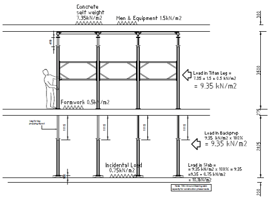
Figure 4 – Backdrop redesign
Grateful for any thoughts or observations on the logic above. Also, from others experience, is it normal that there is so little capacity in the permanent design to allow for the temporary construction state?
Thoughts on over excavation of a contiguous pile retaining wall…
I’m currently looking at the implications of over excavation on the basement (passive) side of a contiguous piled retaining wall. Whilst onsite I became aware that the sub-contractor responsible for the basement reduced dig had moved beyond a hold point before another sub contractor had completed the temporary reduced level on the retained (active) side. The reasons for this are numerous but boil down to poor communication and management of the required design construction sequence. Figure 1 below is a sketch of the wall cross section during final construction and temporary cantilever states in accordance with the design checks conducted.
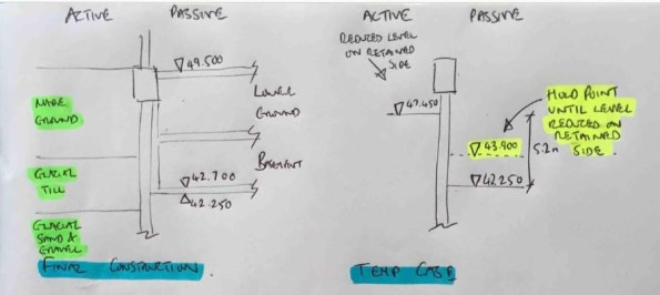
Figure 1 – Final construction and temporary construction stages
In order to understand the impact of this error I wanted to analyse the impact of the worst case (figure 2) where the full passive excavation had been completed and no excavation had occurred on the active side. Note that fortunately work was stopped on site prior to this case occurring!

Figure 2 – Worst case if construction sequence followed incorrectly
The initial WALLUP retaining wall analysis (step 1) gave a minimum pile length for stability of 12m from pile platform level (PPL) to the toe at 39.1mOD. Re-analysis for the worst case shown above caused an increase in the max BM, shear and displacement of the wall in SLS conditions and a failure in ULS conditions due to passive failure. This would be a simple conclusion if the wall had been constructed to the 12m length from the original retaining wall design. However, the contiguous wall is also required to support an axial load for the planned structure above. The initial analysis of axial capacity (step 2) lead to a minimum pile depth for axial compression of 28.5mOD and a pile length of 20.6m from PPL. This design was based on resistance provided in skin friction below formation level and a minimum rock socket of 1.5m. Note however that the initial structural reinforcement design (step 3) only extends to the depth calculated for stability (in step 1) and was based on the maximum moments and shear from this calculation. The image below summarises the initial pile design results.
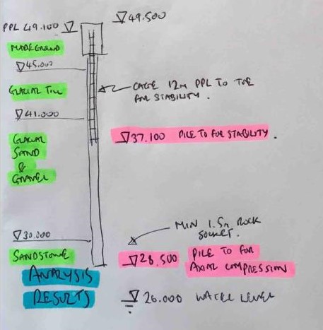
Figure 3 – Initial design analysis results
So, drawing conclusions now on the effect of the over excavation shown in figure 2 becomes slightly more difficult. My initial thoughts are:
1. The passive failure issue is now removed due to the increase in pile depth.
2. There is still an increase in BM and shear force that would mean the structural reinforcement would be under designed and could lead to an STR failure.
3. The structural reinforcement should extend down to the new pile toe depth for stability.
4. There would be an increase in deflection of the wall which could lead to other issues including eccentric loading in the final permanent state.
I’d welcome any comments or thoughts on the above logic or any conclusions I may have missed.
Online CPD – ICE CPR presentations
Whilst searching through the ICE events page looking for CPD events in the Manchester area I was presented with only 2 search results, a Fellowship workshop and a student pub quiz. Acknowledging that I may not be quite ready for the first and questioning the output I would get from the second, I widened my search to see what past lecture recordings were online.
It was then that I found a recording of the James Rennie medal final for 2017 (link here). As detailed on the ICE website, “The James Rennie Medal recognises the best Chartered Professional Review candidate of the year. This year’s final will feature ICE’s top three Chartered Professional Review (CPR) candidates of 2016. They will each present and defend their CPR reports to an audience.”
I found it a useful insight to CPR presentations, even if it is currently a year or so off. Hopefully it’s of use to others out there if you weren’t already aware.
Angel Gardens Teaser – Darwin Award nomination

