Archive
Bridge Parapet Traffic Barrier Design
It has been a while since my last offering but now that my thesis is in and forgotten for the time being and I have finally started my CPR reports here is an update on life in the design office.
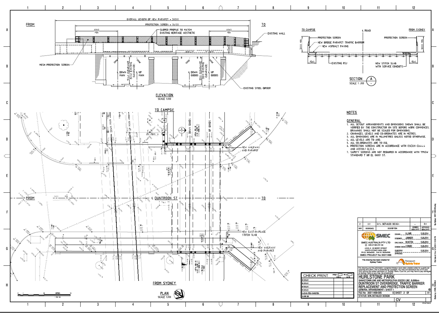
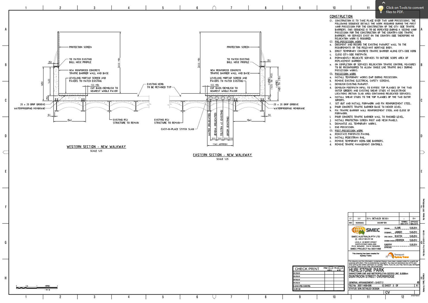
I seem to be the popular choice at the moment to compile and submit tenders, which doesn’t seem to be affected by the fact I have not won any yet because I have just received another one (no doubt my last) while also currently managing three design projects. Over this attachment I have been involved in nine projects (6 tenders and 3 design/PM). The one I have been working on intermittently over the last few months is the detailed design of a traffic barrier to replace an existing masonry parapet in order to comply with current standards. I have subsequently designed a cast in-situ barrier to be constructed on the outside of a 100 year old ‘jack arch’ rail overbridge. I have also modelled the bridge using Microstran to see if the existing structure can accommodate the traffic impact loads. A traffic assessment at the concept stage identified that an intermediate traffic barrier performance was required which stipulates an outward horizontal load of 180kN at 1.1m above road/footpath level, as well as a longitudinal load (to be applied simultaneously) and a vertical load (to be applied as a separate load case). The Australian Standard AS5100 (Bridges) does not explicitly provide a detailed analysis procedure for bridge barriers. As a result, current practice uses American Association of State Highway and Transportation Officials (AASHTO) design procedure based on yield line analysis. The design deliverables for the project are; Concept, 30% detailed, 70%, 100%, IFC. I have just finished getting the 30% DD drawings together to submit to the client (Sydney Trains) by the end of this week in a hope to have the 70% design complete and submitted by the time I leave. I have had to commission a Statement of Heritage Impact (SoHI) and I am now in the process of getting the environment team to produce a draft Review of Environmental Factors (REF) that may be affected by construction such as dust, noise, heritage, social and economic impact to the area. Because it is an overbridge that spans over two rail lines the work will impact rail services during two planned 48hr possessions as well as closing one lane and possible both to vehicle traffic during construction. The amount of work and consideration involved for all aspects of the project all stems from successfully identifying the stakeholders at the very start and you soon realise how many people, organisations and authorities are involved in successfully implementing a project. Below are the drawings at 30% design not showing reinforcement.
I have also been involved in ongoing managerial aspects with the maintenance centre column repair design as per previous posts and a fire protection upgrade design on a cable shaft at central station in the middle of Sydney CBD. I have not carried out any design for this but I have been given the job of PM to bring the project to completion. I also recently submitted a tender for a 1.7km cable route design which was valued at just under $300K with a rather vague scope of works. There was little time to clarify or ask for more detail on most of this – largely because of the fair tendering process every consultant must be informed if a question is asked and meanwhile you lose precious time which you may not have – so I compiled it based on the site inspection and project brief. The client (Sydney Trains) subsequently came back to all the consultants that submitted a bid and have changed the scope somewhat. It appears they put little thought into the original brief and this additional information contradicted previous information. I subsequently revised our originally fee to just under $400K having it reviewed by senior management. The whole episode made me view the client as very unprofessional and rather annoyed me. For instance one comment stated that all assumptions in our proposal should be deleted and the proposal should be based on factual information and the fee should account for the risk accordingly – what planet are these jokers on? It seems very odd – and the seasoned pro’s in the office viewed this in the same way – that the client expects to be entirely risk free. Especially if their own SoW is woolly at best. One of the first tenders I did had a 1000 page brief with various attachments and it was almost too much information, this was a 3 page brief with a rather ‘chip shop’ ppt presentation attached to it. When trying to compile a lump sum fee it very difficult to try and price a project when you haven’t got enough information but you want to be competitive. If the client is not clear on what he wants and asks the design consultant at tender that he is to tell them as part of the scope – which seems quite common in Australia – then surely the client must accept a certain level of risk because the supplier will have to make even more assumptions at the tender stage due to lack of clarity. I would be interested on everyone’s views on this and wonder if any of the other phase 3 lot have been involved in tenders and have had similarly clueless clients?
On other news, the family enjoyed a nice cruise up the eastern coat of Australia at the start of April up to Cairns and the Barrier Reef which was great. Ethan is like the energizer bunny and never stops. Being on a ship meant it was an easy way to travel as your hotel goes with you and by the end of the holiday everyone seemed to know Ethan by name having seen him run about the place for the past 2 weeks with me calling his name trying to keep track of him. It is hard to believe he was only 6 months old when we arrived in Australia and he is now fast approaching his 2nd birthday and Pip is now 5 months pregnant with no.2!
Bridge Traffic Barrier Upgrade
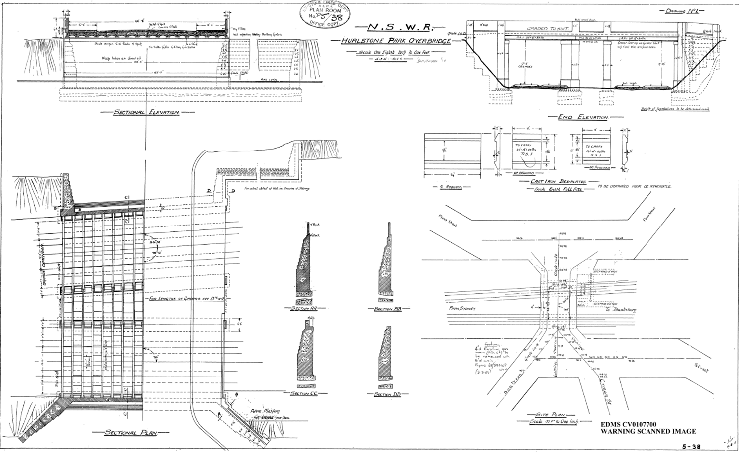
I have been working on a design for the replacement of the existing traffic barrier to one that complies with current standards. The bridge in question is a rail overbridge in the heart of Sydney, it is approximately 100 years old and of ‘jack arch’ contrsuction. Jack arch bridges are somewhat more prevalent in the UK rather than Australia and the tendency here is to Heritage List a structure of that age in an attempt to broaden or find some cultural significance. Fortunately the bridge itself is not Heritage Listed but some of the surrounding rail buildings are which may impact the design aesthetic of the upgrade. A Statement of Heritage Impact (SoHI) has been commissioned which will form part of the Review of Environmental Factors (REF) which at present is unlikely to cause any major dramas due to a previous upgrade in 1994 which replaced parts of the brick barrier/parapet wall to a metal railing. So in effect the current heritage aesthetic is not really in keeping of early 20th century and a full replacement is more likely to improve uniformity.
At present I have designed an L shaped pre-cast section to be retrofitted on top of the current I beam-jack arch arrangement but due to the close proximity of a gas main I am unable to get the base to span across two of the steel sections and current arrangements have the pre casts ection chemically anchored into either the existing fill or more likely new concrete fill which means the jack arch will have to be removed. This is a design I inherited from the concept design stage and I have taken it forward and designed the concrete section to current traffic impact loads which conform to a ‘regular’ level of performance (250kN horizontal load acting across 1.1m at a height of 1.1m above the deck surface). I have built up a model within Microstran of the deck to see how the forces are transmitted through the various members and right at teh start it seemed obvious that the torsional capcity of the outside RSJ would govern. This is because there is very little lateral restaint. I modelled the deck using RSJ’s and plate girder longitudinally as per the originally drawings and then inserted masonry blocks between the girders to simulate the brick/concrete infill of the arches. There are steel tie rods between most of the girders but for the sake of conservatism I assumed there contribution to be negligible. There is some guidance in the HA’s DMRB, BA 16/97 and BD 61/10 which if you take the conservative approach as we don’t know what the fill between the arches is made up of requires the bridge to be analysed non-compositely. I thought I would try to ascertain the torsional capacity of the outside girder and found out that it is more complicated than I or anyone else in the office cares to pursue. Ultimately an I section will be affected by pure torsion (think G’s and J’s from phase 1) but warping torsion will govern. It seems design codes around the world tend to either ignore it or advise you to change your design so that torsion is insignificant and nothing to worry about.
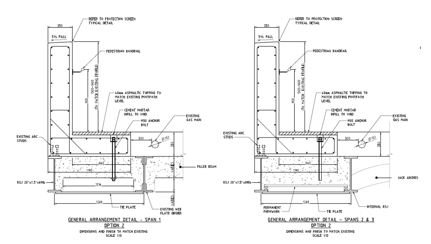
I think the design needs to enable the precast section to span over at least the inside two girders so that shear studs on the top flanges can enable the end section to act compositely and engage more of the deck due to the impact load. This will also mean that we will not have to remove any of the jack arches which will mean we won’t need any temporary works underneath the bridge to protect the tracks and ultimately mean less construction time and distruption due to weekend possessions because we could do all the work from the top. Alternatively I think some for of tie plates will need to be welded onto the bottom flanges to provide the required resistance which means further work to be carrier out from underneath. Providing this additional room for a wider pre cast section to span will result in haing to relocate a number of services (at least the water and gas mains and probably fibre optics to within conduits placed within the precast sections. I think this would still be an easier, safer and quicker way to carry out the works ratehr tahn being afraid to go near the gas main and designing around it which seems to have been the method previously employed.
Someone happened to drive past the site the other week and noticed that all the services within the walkways had been marked out. This would be useful information and I would have had to have employed someone to do this very shortly but it has taken me two days so far without success to try and track down who initiated it so I could get the survey data. The council as well as the asset owner no nothing about it, I have concluded there must a rogue contractor out there armed with a GPR unit locating services around Sydney at will for free!
I designed something
It has been a few weeks since my last blog largely because I have found it hard to bring myself to again ‘tippy tap’ away on a keyboard following the delightful months of Jan and Feb report/thesis writing. Since my last blog I have gotten very little sleep because I believe my child may be possessed by the devil between the hours of 2000-0700 hrs but I have also done a few proposals and some designing finally!
Proposals/Tenders
Since starting I have been given two proposals, one for TfNSW (Transport for New South Wales) – yes the name is probably copied from London – and one for Sydney Trains. Sydney Trains are actually a entity of TfNSW but becasue they are the train service operators they do have a slightly different approach and format to proposals than if it were a new TfNSW project. Both have exposed me to the way proposals and the important lump sum fee is derived which I covered last time. Becasue I have managed both of these proposals I will PM both if we end up winning them but at present nothing has been heard which is probably not a good sign. Subsequently I am slowly being drip fed other proposals as they come up and have just completed a design services fee for a multi-storey car for an architect who has been approached by a tendering contractor for a TfNSW Design & Construct (D&C) contract. I only had a day to do this but the architect has had the proposal for a month which suggests they have probably given it out to other consultants and receievd rather shocking prices back or just wanted a fee to compare previous quotes to. Either way they seem to like it becasue another proposal came my way this morning for a similar car park – I may get branded “the car park guy” very soon! I think I covered pricing details in my last blog, needless to say it is not very scientific and involves just estimating the amount of hours you think it will take across the multiple diciplines to achieve the specified deliverables as set out by the client. The design stages seem to get named differently depending on the client but generally follow this sequence; System Definition Report (SDR (concept) – 15%) stage, Preliminarry Design Report (PDR – 50%) stage, Critical Design Report (CDR (detailed) – 90%) and then Approved For Construction (AFC) stage. Between each stage there is a least a 2-4 week review procedure with the client to get through which can take longer and is why many sub-consultants are very wary of the smaller jobs as the margins are tiny and in this business time is definitely money. Everyones hours are acconted for against a project number and every job I have come across seems to be a lump sum price. The final parts of the design stage are often in the form of construction support (answering Request For Information’s (RFI’s)) and of course As-Built or Work As Executed (WAE) documentation and drawings which formally records the changes to the original design throughout the construction process as well as confirming that the the contract has been fulfilled by the Contractor.
Eveleigh Columns
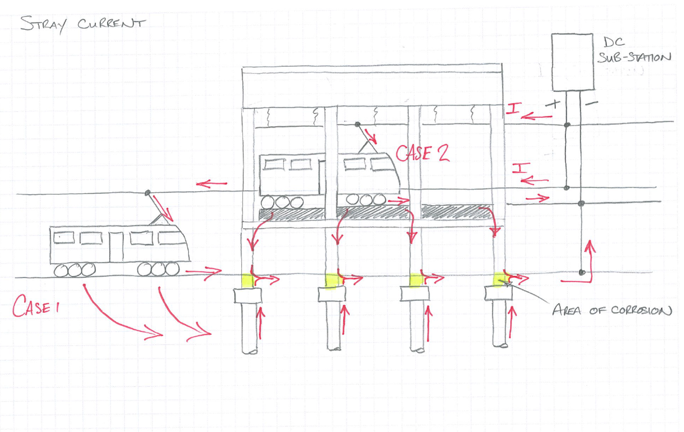
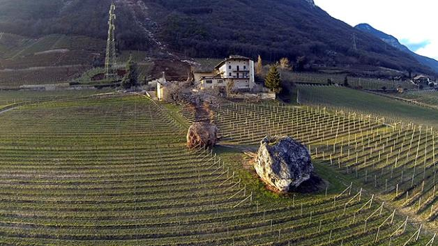
The Eveleigh MC column deterioration due to corrosion has now progressed and I have produced a reference design for the client so that a Design & Construct contract tender can be issued. As I mentioned before, it was believed that stray traction current may have been causing the corrosion. I also remember the great orator may have asked a few questions which I will endeavour to answer here. Firstly the concrete strength that I used as the basis for the original structural capcity check was low due to the variable results of core testing, I did not use a strength 1.64 dev below a mean value, I used the following equation from the Australian Standard which equates a characteristic value of a sample by taking away the (sdev of the sample x an S value) from the average. Secondly, the thought regarding the mechanism of electrolysis taking place was due to the current from the OHW finding its way back to the substation via one or both of the tracks and that the building was parallel to the tracks and I assume that the substation is also within close proximity of the building, then stray current was being conducted through the piles and columns, again I assume because this was a shorter path for the current to take therfore the reinforcemnet was acting as a cathode with the ground and the ground and piles acting as the electrolyte. In this example there is also a second case to support the stray current theory and the more likely, this is due to the OHW and tracks within the building with the current travelling down the raised track supports and through the columns in the basement to the ground. There is a couple of sketches below to try to explain this a little better or confuse you even more!

We ended up getting a sub-contrator in to measure any current flow within the columns and concluded in the end that stray current is very unlikely to be the main cause of corrosion. The fact that there is no ground slab, the basement has poor ventilation and is very hudid, as well as the quality of concrete and lack of adequate cover in places suggests these issues have accelerated carbonation attack of the concrete to the depth of the reinforcement. Chloride attack has also been ruled out from ground testing. Although it wasn’t in my scope of work I wanted to investigate the mechanism of the corrosion further which resulted in me involving other people who after a while wanted the project number to charge their time too, which was probably not expected by my manager. I think because the client has had little idea about what they want this has been a job that SMEC want to close out and move on from quickly. My investigation has determined that the likely cause is from a differential aeration corrosion cell formed between the two environments with which the column sits i.e the ground and humid basement area, coupled with poor quality porous concrete. Oxygen not only enables a corrosion reaction by maintaining a cathodic reaction, but it can promote one. This occurs where there is a difference in the
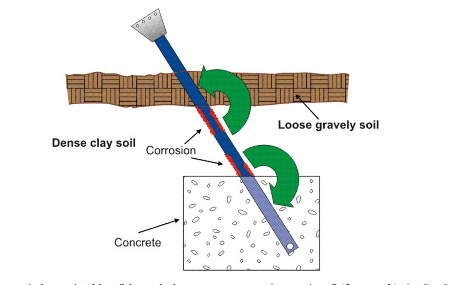
concentration of dissolved oxygen between two points of the same metal surface. Hence the poor quality of concrete has enabled oxygen to contact the reinforcement steel. The below diagram explans how a differential aeration cell works, the portion of the shaft in contact with the clay type soil acts as an anode to the portion of the shaft in contact with the looser gravely soil, which is consequently the cathode. This can be thought of as a similar scenario to the columns where differences in porosity can lead to an oxygen concentration corrosion cell:
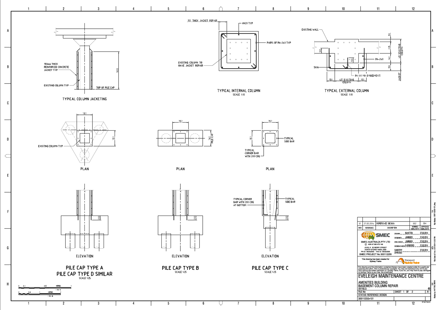
The CP option has now been discarded and the client wanted a worked up design for the repair of the columns so that they can engage contractors to price and execute the work. My solution was dependent on the severity of corrosion within the columns which we will not know until a contractor is elected to carry out the work. I then looked into treatment and patching products. I ended up modelling different levels of corrosion depending on what may be found by the initial investigation by the contrator which would then trigger a particular repair option of either localised patching or constructing a RC jacket around the column. I determined that up to 15% reinforcement section loss on either a corner or single face could be accepted before a jacket would have to be constructed, this was based on providing a further 50 year design life to the structure. An even, overall section loss throughout the column of 40% would also be acceptable but is highly unikely to occur. Any reinforcement section loss above these levels would require a jacket of concrete to be constructed around the column(s). I also had to think about the methodology and sequence of works. Having a better understanding of a contractor it would be a fair to assume they would start hacking out concrete that probably doesn’t need to be removed and more importantly would affect the structural integrity of the whole building, certainly if multiple columns are repaired simultaneously. This required a Safety In Design (SID) process to be carried out, which is pretty much just a risk assessment tool which identifies the main hazards and controls as well as the residual risk post control. In this case, measures such as temporary propping in some circumstances but prodominantly trying to eliminate the risk by only allowing a specific sequence of work to take place, so that sufficient redundancy remains within the building and ensuring the building loads do not increase – the use of the building does not change throughout the works. Below is the drawing that – along with a page of notes – accompanied the design report and performance specification (methodology):
You don’t see that every day!
This is insane, its got Wilie E. Coyote all over it!
Dodgy looking columns.
Having completed and submitted the tender for the North Eveleigh 11kV relocation project the other week I moved on to two other projects which are both part of the Rail Panel work. This panel consists of three consultants for which SMEC are one that get the honour of submitting proposals for various maintenance and upgrade works for Sydney Trains. Although some jobs are rather chip shop there are plenty of gems on offer and as the panel is a three year agreement it has provided a steady revenue for the rail structures team which I think was greatly appreciated last year.
The first is another tender of what Sydney trains call a Request For Proposal (RFP) for some building modification works on a substation about 50km north of Sydney. I attended the site inspection and even to me semi-trained eyes it looked like a fairly straight forward job. The intention is to remove certain outdated equipment and provide an admin room in its place as well as a seperate extension on the opposite side of the building to house a new DC switch room. I have engaged an architect, surveyor, building services consultant, building code compliance consultant and the pertinent in house specialists and will work on the proposal next week for submission on Fri. Thankfully there is no electrical work to be carried out like the last tender so I hope to control costs a little bit more to get a competitive price together. I’ll update more on this next week I am sure.
The second project moved my focus back to Eveleigh but on the other side of the tracks where a maintenance centre is located. Another consultant from the panel had originally been engaged to conduct an investigation of the basement columns where corrosion and subsequent concrete spalling had been observed. The initial concern was whether there were any structural capacity issues. We were asked to comment on the report findings and state whether we agreed with them. The original report concluded that up to a 50% loss of reinforcement section would be acceptable and that the current imposed loadings were not likely to be near the design loadings. The actual level of corrosion has not been detremined and although I haven’t visited the site the photos I have indicate that it is quite bad in places.
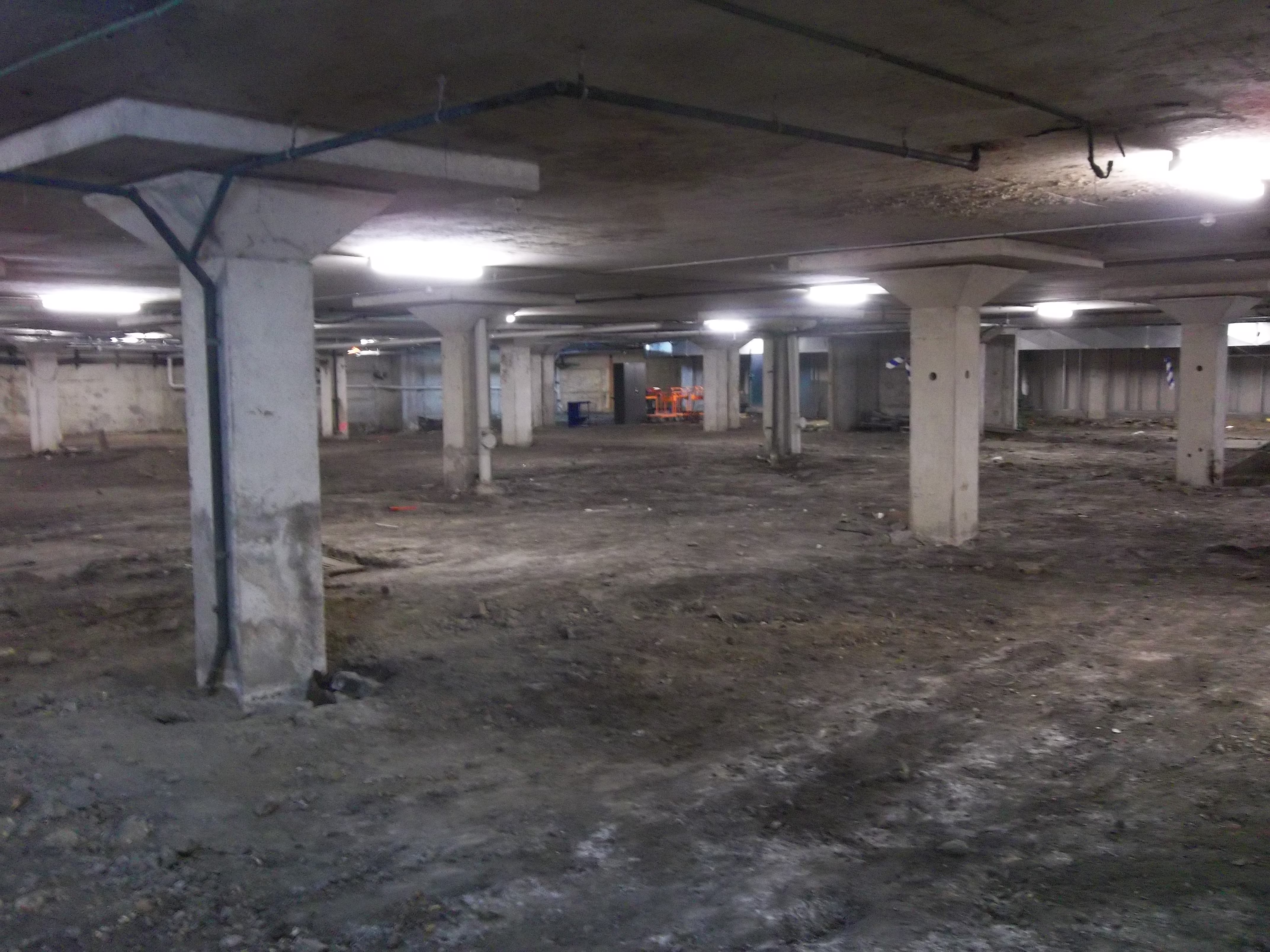
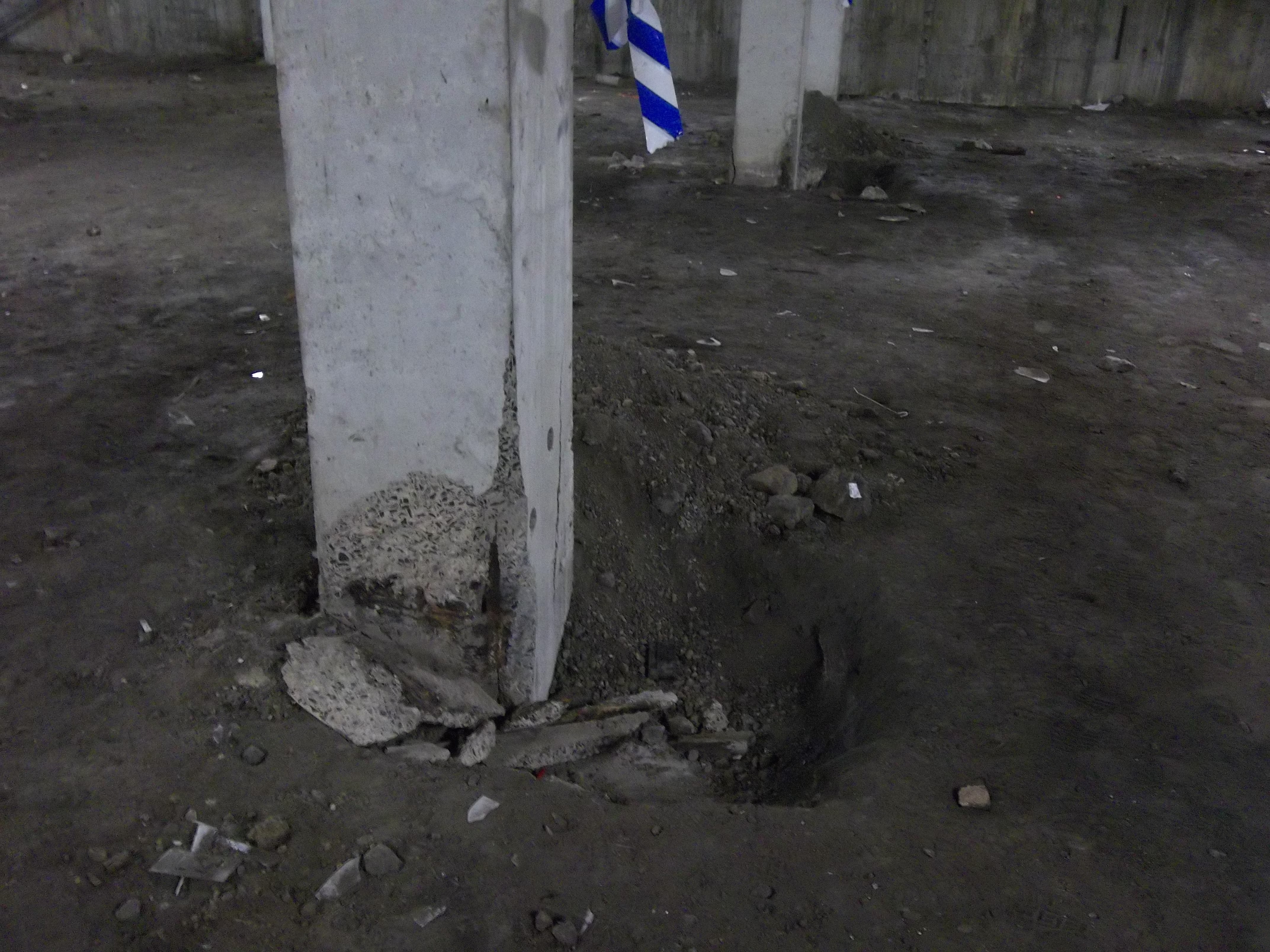
Initial thoughts were that stray current may be the cause of the corrosion. The tracks run parallel to the depot and it was proposed that the piles were picking up stray current from the tracks and conducting it to a point closer to the substation. However, the corrosion has only been observed above ground level and when the ground to the top of the pile cap was investigated there were no signs of corrosion. It must be pointed out as can been seen from the photos that the area of concern is approximately half the footprint of the building and there is no ground slab, the other half of the basement is in good condition (has a floor) and is used as an underground car park.
![train1[1]](https://pewpetblog.com/wp-content/uploads/2014/01/train11.gif)
Apparently, the rate of corrosion from stray current is 9kg/Amp/Year. When iron corrodes by stray current, or by other means, the iron ions have to combine with anions which is commonly oxygen, therefore the corrosion product of iron is generally iron oxides or rust which are insoluable. However, the rate of diffusion of oxygen into concrete can be slow and insufficient to combine with the quantity of iron ions being produced. This means the iron will combine with other anions such as sulphates, chlorides etc which are soluable and so no visible corrosion product exists except a ‘shiny’ surface. The disadvantage of this is that severe corrosion and loss of reinforcement section and structural capacity can occur before corrosion has been identified. The exposed reinforcement shown in the pictures is all covered in rust and so it was assumed (by a specialist stray current consultant) that stray current was not a major factor in the reinforcemnet corrosion but it could have occured after. As a result I compiled a report (more of a memo really) that proposed firstly a Cathodic Protection system to treat the possible cause of the corrosion and a physical column repair method involving ‘jacketing’ the columns in a 150mm RC layer. A few days later the client responded saying that they do not consider the stray current as an issue (the basement is poorly ventilated and conditions are very humid), therefore they did not want to pursue the CP option (which in their eyes came with an unsustainable electric bill) but they asked for a refernce design for the jacketing option. At present I am working up the details for this option which will assume the existing reinforcement in the columns is not contributing and so additional reinforcement will be placed on the outside. This is likely to increase the current 457mm square dimension of a 2.6m long column to 757mm square which is one short, stocky column.
Going back to the initial structural capcity check, I did not agree with the previous consultants conclusion that 50% loss of reinforcements section could be accepted (I calculated, well mainly an excel SS calculated) that only a 25% loss would be acceptable. I thought this would be a bold call considering a technical director did the initial calcs it appears is was due to the assumed compressive strength of the concrete. They had assumed 25MPa but I had the benefit of using actual core samples that were tested at various locations which using the code (no. of samples, sdev and all that) I used a value of 19MPa. My issues with all this so far is that firstly the actaul state of corrosion or loss of reinforcement section has not been determined and it looks like it will not either so there is a lot of assumptions. The second is the cause, it appears that the basement conditions may be the primary casue but to my mind stray current has not been ruled out and could still be the cause because no intrusive testing has been carried out. The big fat caveat with my design proposal at the moment is that this could be a ‘band aid’ job and unless stray current is conclusively ruled out by measuring the presence of a current flow through the columns and the basement conditions are addressed then at some point in the future the reinforcement will corrode to the point concrete spalling again. In fact any new reinforcement introduced to the columns without addressing stray current will be anodic to the existing reinforcement and thus increase the rate of corrosion in the new reinforcement. I will update again next week on how it all goes.
A bit like pulling teeth!
Well, its fri afternoon and I am coming to the end of my second week at the design office and have come to the conclusion already that this is not for me. The office is entirely open plan even the managers are scattered about without any sense of order but it is a pretty soul less place. Everyone seems very focused and confident in what they are doing and it almost seems like an event when someone gets up and goes to the toilet – which is me the majority of the time as I am now back on coke zero to try and get through the next 6 months so I piss regularly!
As for the actual work, on my second day I was given an Invitation To Tender for a rail job and was told it needed to be in on 15 Jan and as the company is taking 3 weeks for xmas that means 6 working days. My first thought was that, thank god I don’t have to design anything yet and maybe this will be a good job to get stuck into and learn about the tendering process. The job was to relocate some 11kV feeders from OHW to undergroud and construct a new switch room and access track. Not a big job, but having thought I was going to the structures team to probably design bridges I suddenly found myself on a rail job tendering for an electrical job. I am actually part of the structures team but within the rail structures team and so this small project landed at my feet. In the end it was such a manic 6 days I am not sure I leaned as much as I was hoping as it seemed to turn into a bit of a phase 1 design exercise scenario! – not as bad as I did go home every evening. It has emersed me into costs again and how a tender is priced which was my main focus as well as pulling in all the relevent specialists to get there input. The tender required about five seperate sub-consultants and the same number internally from SMEC who all had to produce a methodology for their input along with assumptions and exclusions. I have learnt that if you have any doubt in your understanding of the tender documentation or just can’t be bothered to read it all then cover your self my saying exactly what you are providing within the lump sum cost. I was rather surprised at how rushed, or late the tender was issued before it needed to be submitted but I think this was more down to SMEC than the client. I suppose you need to be quite ruthless with the time you allocate to a tender as it is unpaid work with no guarantee of a win. I attended the client site inspection on day 3 still not really knowing what was going on and having had very little time to read the 965 page tender document issued by the client. An electrical engineer from a sub-consutant we were partnering with was going to attend with me but pulled out at the last minute and when I got there I think all the design consultants of Sydney were present. Having chatted to a few of them it became apparent they hadn’t read any of the tender docs and I think one guy was only there because he saw a a queue of people on the street and thought he would join us.
I managed to get the tender together with a few hours before submission and then had to present it to the Regional Manager to justify the price so he would sign it off. In simple terms, the in house costs or Direct Labour Costs as well as the reimbursables (sub-consultant fess) once a certain multiplier is thrown in gives you a contribution percentage. Corporate and regional overheads come in at about 36% total so anything over this is profit. Most jobs certainly in transport over the last year have had to be tendered at about 40% contribution to have a chance of winning and this tender was settled at about 42% with the total at AUS$ 716,000. I think the general consensus was that the price would need to be more like 650,000 to win but the electrical sub-consultant we have used is a little pricey. We just need to wait to see if we get this.
Following from that I have been given a RC structure where the basement column reinforcement has coroded and caused the concrete to break away. My job at the moment is to assess whether the structural capacity of those columns is sufficient. More on that next week I think.
Otherwise, the hours are so far pretty reasonable and I get to drive or cycle in every morning over the Sydney Harbour Bridge which is a pretty good view.
Dickson Road Overbridge – Glenfield to Leppington Rail Line
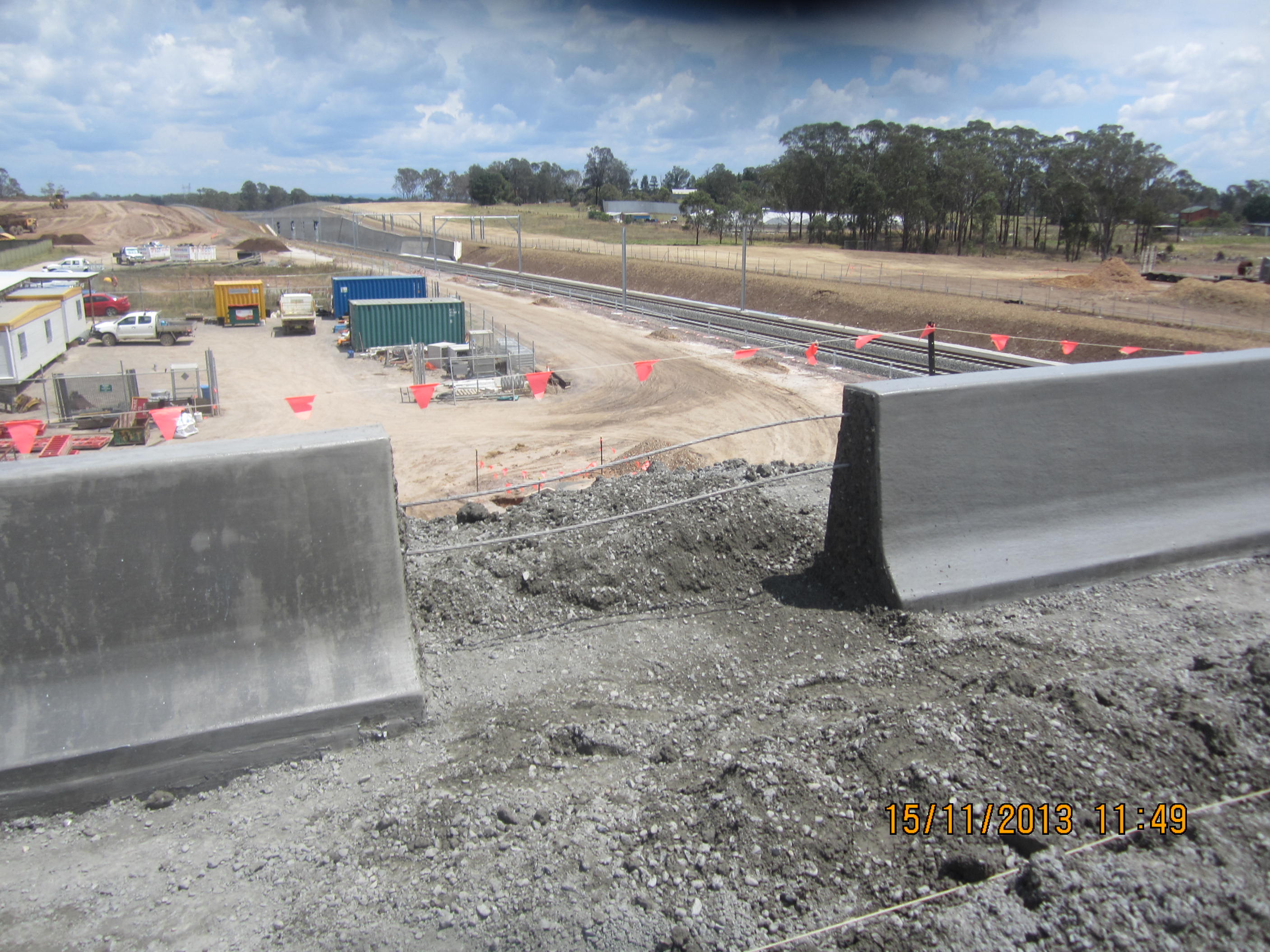
I forgot to post a photo but here is my completed creation over the past 9 months!
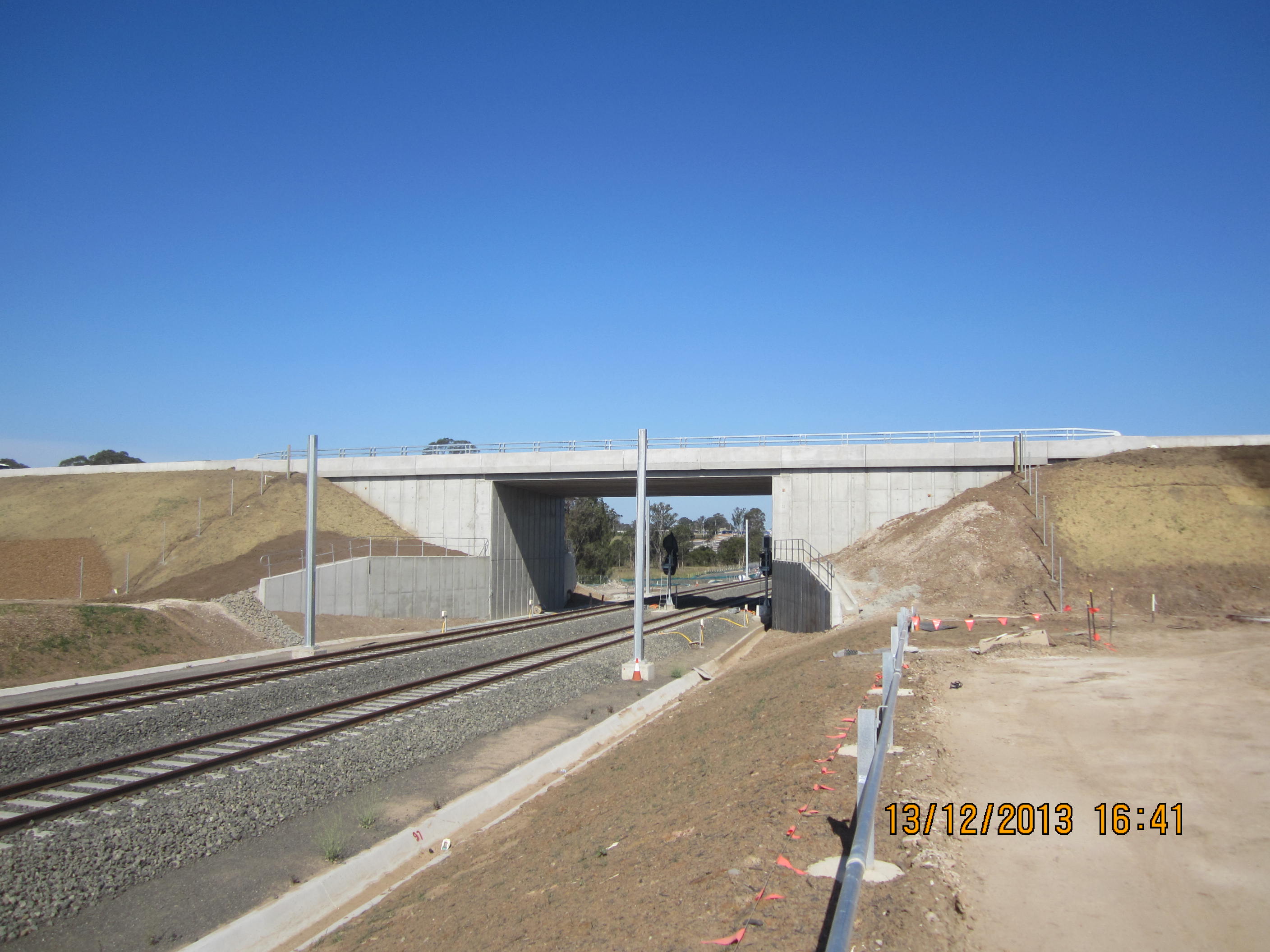
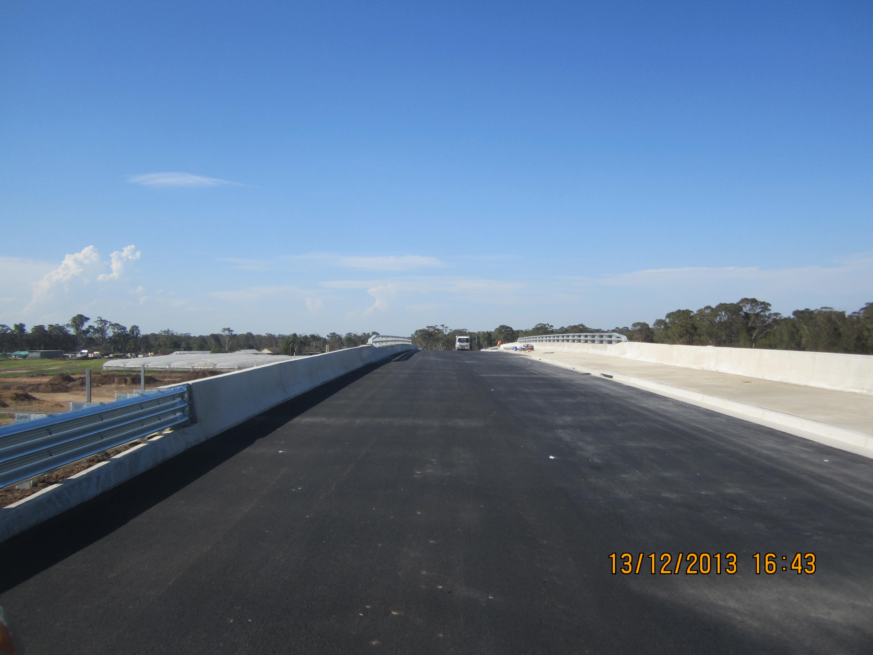
Bridge complete….just about!
After coming back from a great holiday in NZ I pretty much expected a complete bridge and was quite surprised at how little had been done. The bridge is very close to complete but when I left on Fri evening there were still the throw screens to install and a fair amount of concrete surface work on the barriers especially where the slip formed barriers meet the sections that had to be hand formed. When I went on holiday there were four very small concrete pours to complete which and `i had arranged and booked everything in which would have only taken a week so I am not sure what they have been doing for the other 2 weeks. As a result I have still been on site a lot more than I anticipated in my final week rather than closing out all the QA paperwork and closing documents such as the ‘red line’ drawings and RATM’s. I have forgotten what RATM’s stands for now but it is simply a spreadsheet that documents all the contractual requirements where I had to write or file the relevant evidence that proves we have met the requirements such as a work lot number or particular photograph.
My last post showed one of the slip forming runs with a missing portion. Well, we did four separate runs of approximately 18-20m and that was run 3 which we did on the morning of the second day. That was simply a product of pour concrete supply by the concrete supplier. The concrete mix was a 10mm slump mix and as such they limit the transport load to 3m^3 per ruck. Throughout the two days even with constant phone calls we had a very poor service to the point where I requested that the project rep came out to visit site. The gap in the barrier was where we were waiting over an hour between loads to the point where the concrete would have gone off in the mould so we had no choice but to break out a section and start agin when the next load arrived. They accepted responsibility and I informed them that I would be putting in a claim to hand form that section which would be back charged to them. When I left for holiday I informed commercial about this but I get the impression it was ignored as the Commercial Manager doesn’t like to rock the boat so close to the end of the project. In my opinion no one especially the supplier wouldn’t have had a problem with this as they fully admitted liability especially when considering other issues we had with them. We were supplied the wrong concrete mix on the first day which was a kerb mix not a type F barrier mix which had 10mm stone rather than 20mm. After I sent it back I argued that this was their mistake and after they checked phone records of the order they apologised but the mix did not work well at first. The first run formed very poorly in the mould with most of the top section missing and having to be formed by hand with a 6 man crew training behind the mould. The subcontractor was blaming a lack of air entrainment within the mix but when I requested the air content of the mix (min of 4%) they said they had no capability to test the air content. The subsequent runs were much better so something changed within the mix. We had a further issue when the supervisor asked one of the excavator operators working nearby to remove some of the excess concrete that had been picked out at the end of run 1. This was now quite hard and as we had a 300mm foundation which had not been separated or saw cut it resulted in most of the barrier cracking along about 2/3 of its length. This meant we ended up breaking out most of run 1 and hand forming in on Dayworks which was expensive.
The roadworks seem to have been pretty slow but were complete when I left aside from street furniture and line marking so it looks like following the Road Safety Audit early next week the road should open next fri before xmas.
I start with SMEC on mon which I am not sure I am looking forward to as it is just going to mean more office work but I am hoping the hours will be more sensible. My commute is certainly a lot shorter so I should be able to bike to work a few days a week. At the moment I have had no official confirmation of how my rent will be paid and I have no car having given back the Ute on Fri. Hopefully I will be able to sort out the details at SMEC face to face with HR as JH certainly don’t seem to be keen to help – I find it ironic that being here to increase my contractual understanding I am with a company that has difficulty in honouring a simple agreement with the RE!
Offline for 3 weeks
I was planning on writing my final phase 2 blog but I have run out of time as I race to try and leave the site in good order for 3 weeks and also submit AER3 before I fly out to NZ early Sun morning.
I will leave you with a teaser which I will wrap up when I get back. Needless to say slipforming is not as easy as it looks to get right!
The rain may defeat me!
This last week has seen slower progress than I wanted, however we have managed to complete the walkway along the eastern side of the bridge and installed the water main and the six conduit runs. We also managed to pour a total of 18m of traffic barrier out of the 108m along both sides of the bridge, although I was hoping to get 27m complete I had further issues with the reinforcement supply. The steel scheduler rarely seems to get the schedule right which has forced me to check every schedule he sends me to try and spot the error ASAP so I can get a timely resupply. In this instance he forgot the end transition barrier steel completely and some for the barriers on the wingwall but after stressing to him the urgency it still took a week for delivery and what was delivered was about 2T more than I was expecting – at $1123.50 a T I’m inclined to send it back and not pay the invoice or cash it in with the steel bin so we can have a final BBQ!
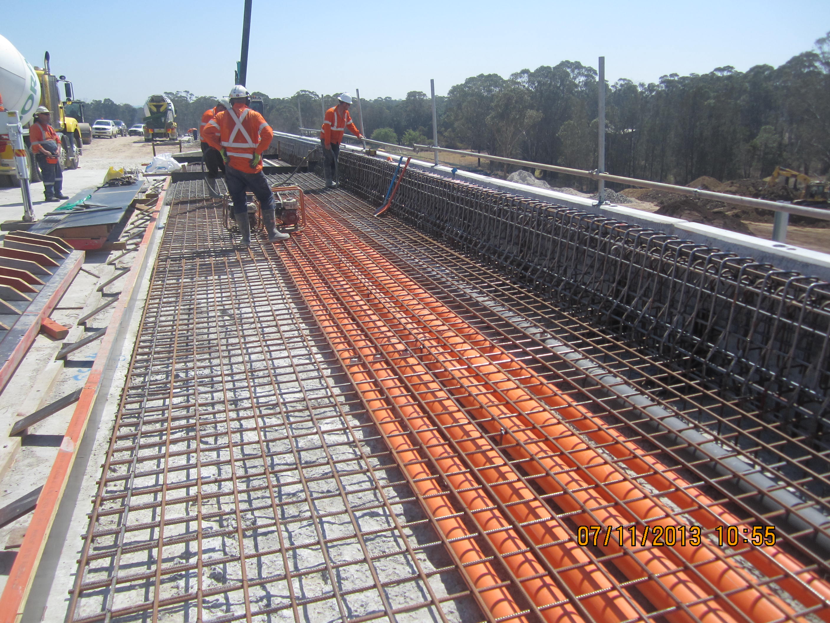
I have had to move the slipforming to the right by two days due to rain forecast for early next week. Usually the weather forecast is pretty useless and the weather can be very different out in the west than it is on the coast but as we haven’t had rain for a long time the met gurus have put up a convincing argument that Mon will be a washout. I am almost looking forward to some rain as it means I will have a chance to catch up with a large portion of my QA paperwork and load it on to the worklot register to pend to the quality coordinator. The main hassle with trying to close lots is waiting for the concrete test results which almost never get issued at 28 days and often take 40 days+ before they reach you. I am currently badgering the concrete supplier the day the cylinders are tested so they can send me the results so that I can pend as many lots before I go on holiday this sunday.
Another issue that stops worklots being closed is outstanding NCR’s. The RMS spec only allows surface concrete cracks of less than 0.1mm after 28 days which basically means any cracks you can see have to reported as an NCR and an RFI also needs to be raised even though the repair method is always the same. This does generate a lot of paperwork and takes time from the engineer.
I was trying to think back to the issues I have raised through the blogs so far (I could look back over the blogs I suppose but hopefully I can remember the pertinent ones) and it has occurred to me that most are still an issue and have not been resolved as they are either sitting with the designer or we have no resources available to currently do anything about them.
Pile concrete mix. The initial issue was that the concrete did not meet the required strength at 28 days but after applying age correction factors to 56 day results (the concrete supplier argued that it was a 56 day product therefore it may not reach 50MPa after 28 days) and an assessment of – there near enough – the designer accepted the strength results we had. A later issue was that when we looked through the batch records they had actually supplied the wrong concrete mix for two of the ten piles which was a mix that was not even a project authorised mix. This mix had a high cement content, higher than the max allowable limit according to the Durability Assessment Report (DAR) so an RFI was submitted to accept as is. The designer and Project Verifier (PV) had concerns about Early Age Thermal Cracking and that is still where we are. The advice from the designer who produced the DAR was that we conduct a PIT which in theory we could do if we exposed some of the pile and notched into the face of it but that is a lot of effort for potentially unreliable results so our response was no, please review again considering our solution to ‘leave as is’ which does seem to be the default setting for RFI’s at JHG.
Conduit expansion allowance. Scalabrini Creek underbridge had the Combined Services Route cast into the walkways without allowing for expansion of the HV conduits at either expansion joint of the bridge between the deck and approach slabs. After going back and forth numerous times with the RFI procedure I finally managed to get the services designer to agree that simply cutting the conduits flush to either face to create a 50mm gap would be the most practical and cost effective approach. Concerns about damage to an exposed cable at the joint were dismissed once it was highlighted that a steel cover plate is installed at the top of the walkway and along the deck which will protect the cable. Other concerns regarding pulling the cables through along cut and potentially sharp edged conduits were also toned down once reassurance was given that strict operational procedures would be followed to ensure firstly that the conduits would be cut cleanly and the edges smoothed off and secondly the installation would be conducted with care and spotters at each joint to monitor the cable pull. The actual process of cutting the cables was not an easy process and took me about 3weeks to achieve. In the end I had to get in another concrete cutting subcontractor as the two we had been using were useless. The only thing we could do to reach the lower conduits was to stitch core them using concrete core bits – it didn’t look very neat at first but its amazing what a motivated labourer with a file can achieve. The cables are now installed and the client has accepted the work so issue closed.
Settlement issues. I think I have mentioned a few issues with initial settlement at some of the retaining walls and practically all the bridge approaches. I was asked by the Construction manager to compose an RFI to ask for the settlement tolerances expected and request that any movement below this value be ‘left as is’ and I suppose we are just hoping that there is no movement greater than the figure the designer gives us. The initial response came back quoting something out of an initial design report by the JHG design manager but I have spoken to Senior designer at SMEC who had designed the retaining walls and he said he expected vertical movement of up to 100m on some of the RW’s and certainly on two of the walls we have had 80mm movement which has resulted in the corner of the wall resting and crushing against the corner of a bridge pile cap. I haven’t really had time to pursue this any further as I was instructed to focus on completing Dickson Rd and that all defect work will be addressed in the new year. If I have time I may revisit this with the Construction manager to at least close the RFI. Eastwood Rd overbridge settled 5mm over a 3 week period but it seems to have stopped and the cause has be blamed on poor material being used for the backfill against the abutment. It was probably due to poor compaction methods as well having watched the civil team at work at Dickson Rd doing layers much deeper than the specified 150mm, using a pad footed bulldozer to compact and employing a rather dubious subcontractor to conduct the compaction testing at supposedly every 300mm.
There may be more issues I need to close but I think this is enough for now. Richard, I think you are probably one of the few who are still reading my blogs so if you think of any issues I haven’t covered I am sure you will let me know. The monsoon has just started outside as expected.
