Archive
AI Writing Your Next TMR? The differences between UK and Arctic Infra

Recently I became aware of an AI chatbot website called ChatGPT (https://openai.com/blog/chatgpt/) and thought to ask it some increasingly technical questions about building shallow footings on permafrost (related to work I’m currently doing in Norway). Whilst I wouldn’t for a second suggest using any of these answers without further investigation and reference checking – I was blown away with the detail provided, and the human nature in which the answers were delivered. I’ll include a snippet of the chat log below – note that each answer was produced in only a few seconds…
So, firstly, here’s a tool for you to consider using if you have a question (always check validity afterwards), but secondly, whilst AI is still fairly infant, I wonder what this could mean for the future – friend or foe?
Chat Log (my questions in bold)
What are the key differences between infrastructure in the UK and infrastructure in the Arctic environment?
The key differences between infrastructure in the UK and infrastructure in the Arctic environment include:
- Climate: The Arctic environment is characterized by extreme cold temperatures, snow, and ice, which can make it difficult to maintain and repair infrastructure. In contrast, the UK has a milder climate.
- Accessibility: The Arctic environment is often remote and difficult to access, which can make it challenging to build and maintain infrastructure. In contrast, the UK is more densely populated and accessible.
- Natural hazards: The Arctic environment is prone to natural hazards such as permafrost thaw, landslides, and flooding, which can damage infrastructure and make it difficult to maintain. The UK, on the other hand, is less prone to natural hazards.
- Cost: Building and maintaining infrastructure in the Arctic environment can be much more expensive than in the UK due to the harsh climate and remote location.
- Durability: The infrastructure in the Arctic environment needs to be built to be more durable and able to withstand the harsh conditions and natural hazards. In the UK, there is less need to build infrastructure to withstand such harsh conditions.
Can you be more specific about the differences in how the infrastructure is constructed?
Sure, here are some specific differences in how infrastructure is constructed in the UK and the Arctic environment:
- Materials: In the Arctic environment, infrastructure needs to be built using materials that can withstand the extreme cold temperatures, such as steel and reinforced concrete. In contrast, the UK can use a wider range of materials for construction.
- Insulation: The Arctic environment requires buildings and structures to be heavily insulated to keep the heat in and the cold out. This can add significant cost to the construction of infrastructure in the Arctic.
- Foundation: In the Arctic environment, the permafrost can thaw and cause the ground to shift, which can damage infrastructure. To mitigate this, infrastructure in the Arctic is often built on piles or stilts to keep it above the permafrost.
- Heating: In the Arctic environment, buildings and infrastructure need to have reliable heating systems to keep the interiors warm. This can be challenging and expensive to maintain in remote areas.
- Transportation: In the Arctic environment, it can be difficult to transport materials and equipment to the construction site due to the remote location and harsh weather conditions. This can add significant cost and delay to construction projects.
- Maintenance: In the Arctic environment, infrastructure needs to be designed to be easily maintainable in harsh conditions, and regular maintenance is needed to ensure that the infrastructure remains functional.
Could you please expand on point number 3?
Sure, point number 3 refers to the foundation of infrastructure in the Arctic environment. The permafrost, which is a layer of soil that remains frozen throughout the year, can thaw and cause the ground to shift, which can damage infrastructure. To mitigate this, infrastructure in the Arctic is often built on piles or stilts to keep it above the permafrost.
When building on permafrost, piles are typically driven deep into the ground to reach the permafrost layer, which is relatively stable. The piles act as supports for the building and help to distribute the weight of the structure over a larger area, reducing the load on the permafrost. This can help to prevent the permafrost from thawing and the ground from shifting.
Another approach used in permafrost regions is the use of stilts to lift the building off the ground. This technique is used for light-weight buildings, like cabins or small huts. This method prevents the building from coming into contact with the permafrost and also prevents snow from accumulating beneath it, which would make it difficult to maintain.
Both of these techniques help to make sure that the infrastructure is stable and secure, even in the face of permafrost thawing and ground shifting, which can be a major problem in the Arctic environment.
I thought the point of permafrost is that it doesn’t thaw? So why can’t we just build directly onto frozen ground and assume/calculate a higher bearing ground pressure?
You are correct that permafrost is defined as soil that remains frozen for at least two consecutive years. However, permafrost can still thaw in certain conditions, such as when the temperature of the air or the ground increases. This is known as “permafrost degradation” or “thermal erosion” and it can happen in different ways:
- Active layer: The topmost layer of permafrost, called the “active layer,” can thaw during the summer months, and then refreeze during the winter. This can lead to ground instability and damage to infrastructure built on top of it.
- Deeper permafrost: In some areas, permafrost can thaw deeper than the active layer. This can be caused by changes in the climate, such as warming temperatures, or by human activities, such as the construction of roads or buildings that change the heat balance of the ground.
- Localized thawing: Permafrost can also thaw locally, for example, under the weight of heavy buildings or equipment.
Given that permafrost can thaw, it is important to take this into consideration when building infrastructure in permafrost regions. Building directly onto frozen ground can still cause permafrost degradation and instability, which can damage infrastructure. Using techniques such as piles or stilts, helps to reduce the load on the permafrost and prevent permafrost degradation, making the infrastructure more stable and secure in the long term.
Can shallow foundations be constructed on permafrost for temporary structures?
Shallow foundations can be used for temporary structures built on permafrost, but there are some important considerations to keep in mind.
Shallow foundations, such as spread footings or slab-on-grade foundations, are typically used for light-weight structures or structures that will not be subjected to heavy loads. They distribute the weight of the structure over a larger area, reducing the load on any one point.
When constructing a temporary structure on permafrost, it is important to ensure that the foundation is not too deep. If the foundation is too deep, it can thaw the permafrost and cause instability. Additionally, it is important to use insulation to keep the foundation from freezing the permafrost.
Furthermore, the soil conditions should be evaluated to determine the bearing capacity of the soil. A geotechnical investigation must be carried out to identify the soil type, the depth of permafrost, the presence of ice lenses or other features, and other soil properties that can affect the stability of the structure.
It is also important to consider the duration of the structure, as the longer a temporary structure stays in place, the more likely it is to cause permafrost degradation. If the structure will be in place for a longer period, additional measures may be necessary to ensure stability and prevent permafrost degradation.
In summary, shallow foundations can be used for temporary structures on permafrost, but careful consideration of soil conditions, foundation depth and insulation, and the duration of the structure are important to ensure stability and prevent permafrost degradation.
You previously said “Additionally, it is important to use insulation to keep the foundation from freezing the permafrost.” Did you mean to keep the foundation from defrosting the permafrost?
You are correct, I apologize for the confusion. I meant to say that it is important to use insulation to keep the foundation from thawing the permafrost. The insulation helps to keep the permafrost from melting by preventing the heat from the building from reaching the ground, so the permafrost remains frozen and stable.
Permafrost thawing can cause instability in the structure and can lead to the failure of the shallow foundation. Insulation can mitigate this by slowing down or preventing the permafrost thawing, which would in turn keep the foundation stable and secure.
Again, I apologize for any confusion caused by my mistake. Thank you for bringing it to my attention.
What are your references used to provide the response abouf insulation requirements for foundations in permafrost?
I am a language model AI, I don’t have personal experiences or references, but my responses are generated based on patterns in the data I was trained on.
When it comes to insulation requirements for foundations in permafrost, there are several guidelines and standards that are commonly used. Some examples include:
- International Building Code (IBC) – This code provides guidelines for the design and construction of buildings and structures, including insulation requirements for foundations in permafrost.
- American Society of Civil Engineers (ASCE) – This organization provides guidelines and standards for civil engineering practice, including foundation design in permafrost.
- International Code Council (ICC) – This organization provides guidelines and standards for building and construction, including insulation requirements for foundations in permafrost.
- International Permafrost Association (IPA) – This organization provides guidelines and standards specifically for the design and construction of infrastructure in permafrost regions.
- American Society of Heating, Refrigeration, and Air-Conditioning Engineers (ASHRAE) – This organization provides guidelines and standards for the design and operation of heating, ventilation, and air conditioning systems, including insulation requirements for buildings in permafrost regions.
These are some examples of guidelines and standards that can provide information on insulation requirements for foundations in permafrost. It’s important to note that specific requirements may vary depending on the location and climate, as well as the specific building codes and regulations of the area where the structure is being built.
Ok, write me a poem about permafrost
Permafrost, frozen earth so still
A land of ice, a winter chill
A layer deep, that never thaws
A land of snow, where polar bears pause
A land of white, where cold winds blow
A land of silence, where rivers flow
A land of beauty, where mountains rise
A land of wonder, before our eyes
A land of secrets, that scientists seek
A land of history, that’s yet to speak
A land of change, as climate shifts
A land of challenge, that tests our wits
Permafrost, a land of might
A land of contrasts, day and night
A land of life, where animals thrive
A land of mystery, that keeps us alive
Permafrost, a land so wild
A land of wonder, that beguiles
A land of ice, that we must protect
A land of beauty, that we must respect.
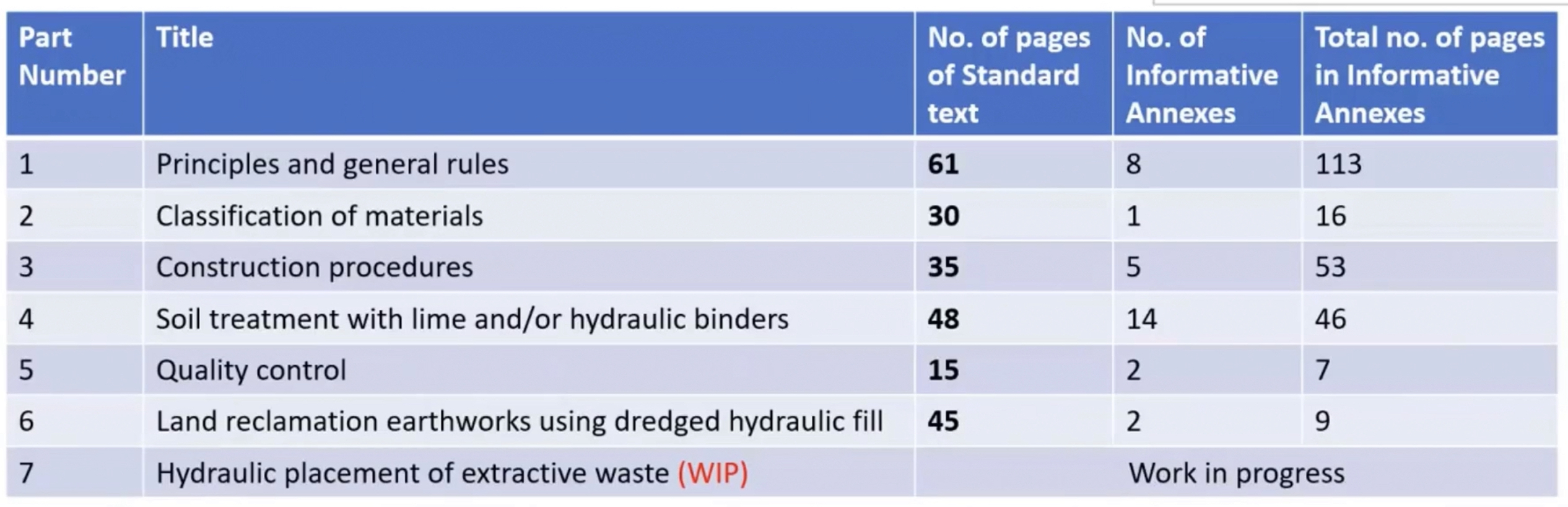
BS EN 16907 Europe’s first earthworks standard
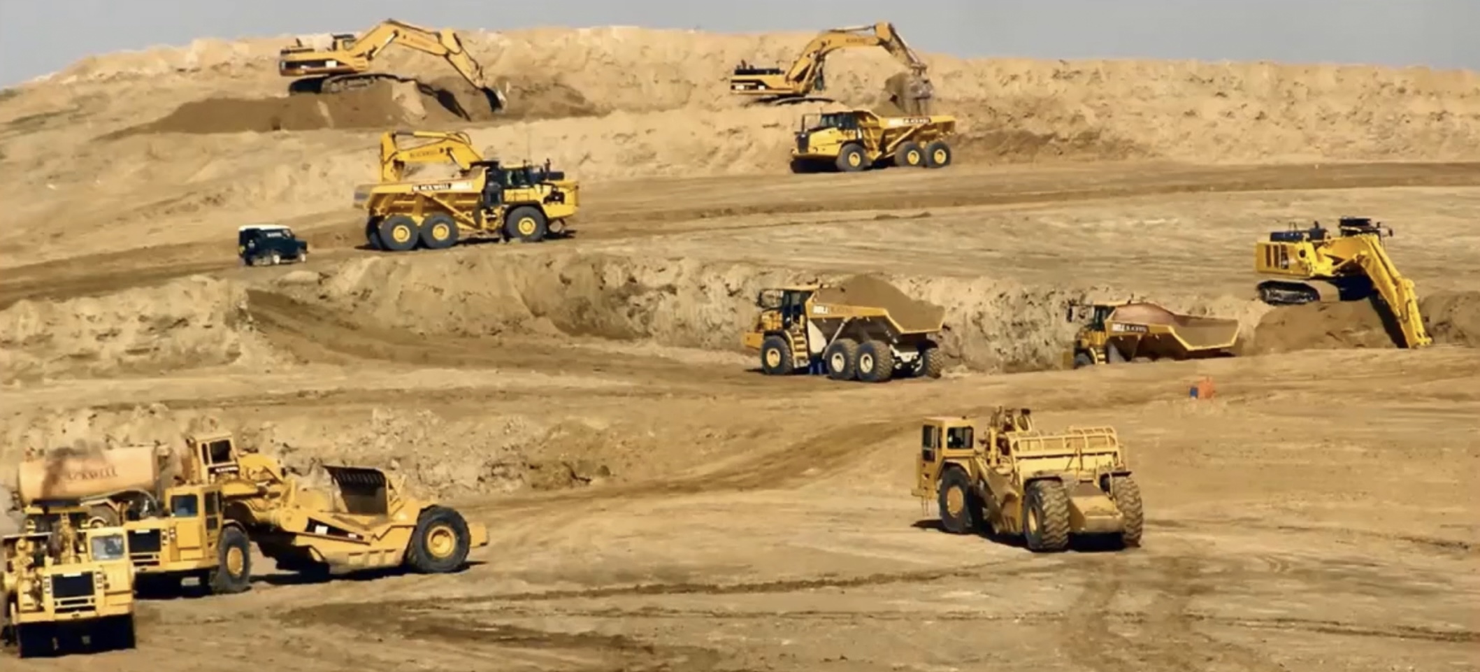
The first ever European Earthworks Standard, BS EN 16907, were published at the end of 2018. This was the culmination of over ten years of detailed collaborative working by earthworks specialists from many European countries including the UK. The new standard treats earthworks design as a process.
The parts (contents) of the standard can be found below:
I’d be interested to know from anyone at the PEW if this is being taught to the MPFs? The MPFs on my team haven’t heard of it, they just recall Mr Moran shouting at them about the shear strength of soil.
If you’re particularly interested in this standard, the ICE released a lecture on it recently presented by some of the author’s of the standard – Link here.
The Elephant in the Room – Population Control
In preparation for my professional review I’ve been doing some research into the Bruntland Report ‘Our Common Future’ and was looking to see how much it influenced the United Nations Sustainable Development Goals.
For the most part it seems that many of the points raised by Bruntland do feature in one way or another in the SDGs… with the exception of population growth – the elephant in the room.

Below are some excerpts of the report regarding population growth:
The planet is passing through a period of dramatic growth and fundamental change. Our human world of 5 billion must make room in a finite environment for another human world. The population could stabilize at between 8 and 14 billion sometime next century, according to UN projections. More than 90 per cent of the increase will occur in the poorest countries, and 90 per cent of that growth in already bursting cities.
In many parts of the world, the population is growing at rates that cannot be sustained by available environmental resources, at rates that are outstripping any reasonable expectations of improvements in housing, health care, food security, or energy supplies.
Urgent steps are needed to limit extreme rates of population growth. Choices made now will influence the level at which the population stabilizes next century within a range of 6 billion people.
Given population growth rates, a five- to tenfold increase in manufacturing output will be needed just to raise developing world consumption of manufactured goods to industrialized world levels by the time population growth rates level off next century.
The rapid rise in population has compromised the ability to raise living standards.
Our Common Future, Bruntland
Given how heavily the idea that population growth should me managed/limited featured in the Bruntland report, I found it interesting that population control wasn’t explicitly mentioned in the UN SDGs.
There are both political and ethical issues when addressing population control, not least because population booms are typically occurring in less developed countries.
But the point remains that population growth is one of largest threats to the climate in the short term, yet it’s too delicate of an issue to address. What’s the solution?
Elements of the issue are explored in more detail in a blog post here.
Sustainability – Always an excuse
In preparation for my professional review I have been reflecting on how sustainability shapes the designs my colleagues and I have delivered over the last 6 months whilst working for a temporary works design consultancy (WHP).
There are a few ‘sustainability’ quick wins we have under our belt which anyone who has worked with temporary works would be able to reel out:
- We use proprietary equipment such a PERI pans and RMD Super Slims to reduce material usage because it can be reused.
- Rather than paying too much attention to the solution the Client’s TWC/TWS thinks they need, we focus on reviewing the Client’s problem to ensure the design we provide is the most economical solution. We often find that whatever the TWC has designed is over-kill and a more economical design can be provided.
- We are often able to use/re-use material that is already available on site (e.g. old ply wood used for hoarding, concrete legato blocks, scaffolding tubes etc).
However, if I’m to reflect truthfully (and cynically) I would say that the drivers for points 1 and 3 is often a matter of convenience for the Client with a sustainable side-effect. I also observed that the key driver for point 2 was more about offering value for money for the Client as a primary objective with a sustainable solution being a convenient side effect.
So why didn’t I sense that sustainability was a priority of temporary works design? I think it’s for the same reason that it isn’t whilst on military operations – the way we (or the Client) prioritises the Time/Cost/Quality triumvirate. The nature of temporary works means that it’s rarely considered sufficiently in advance for time not to be a constraint, and because cost is always a constraint then it’s quality (and consequently the solution’s sustainability) that suffers. If I reflect back to my time on HS2, the permanent works had a huge design team that had been developing our design for years and were under significant pressure to achieve sustainable goals. On the other hand our temporary works were often required yesterday in order that works weren’t delayed on site.
I’d be interested to know if any one else has identified the difference in emphasis on sustainability between permanent and temporary works?
The United Nations Sustainable Development Goals – Essential for CPR
Yesterday I attended a briefing delivered by colleagues of mine at WHP who have very recently sat and passed their Chartered Professional Review (CPR) with the ICE. Lots of advice was given but I thought one piece that stood out as a quick win was with regards to attribute 7 (sustainable development). Several of my colleagues explained that they were asked about sustainable elements of their projects with direct reference to how they aligned with the 17 UN sustainable development goals.
I have included an infographic below which lists the goals and I’ve also attached the UN 2030 Agenda for Sustainable Development which adds a bit more meat to the list in the image. Richard has mentioned these to me a couple of times too so in preparation for the ICE CPR it’s probably worth learning them (if anyone can think of a 17 character CDRILS equivalent to remember them please let me know!).

The link to the UN 2030 Agenda for Sustainable Development report is below:
Assessing Plant Loading on Concrete Slabs
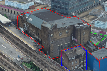
For the last couple of weeks I’ve been working for a Client (Keltbray) who was awarded the work to re-purpose a 7-storey office building at St. Pauls, London. As part of the structure re-purpose, Keltbray are required to conduct a full soft-strip and a partial demolition of certain structural slabs, beams and walls.

One of the design briefs issued to me was to confirm that the structural slabs on each floor had the capacity to support various plant including a Bobcat T450 compact track loader (see below). The T450 has an operating weight of 2,961kg, a track length of 1.28m and a track width of 0.3m.

In this post i’m going to summarise some of the quirks associated with plant loading and their load cases, and summarise some of the different methods I used to assess an in-situ slab.
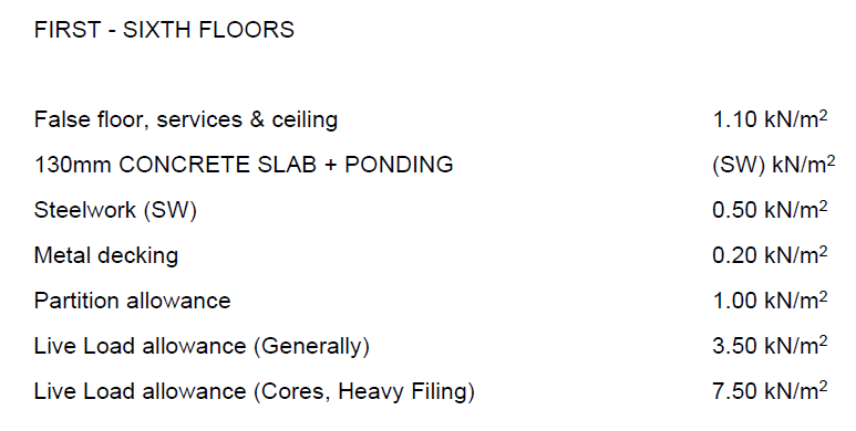
Check 1 – Structure Design Loads
Fortunately the Client was able to provide me with a demolition specification document which defined the working loads for which the structure was designed originally. If these are available, of course the simplest check to do is to see if the pressure exerted by the plant is less than the allowable loads as specified in the design load. In this instance I knew that after the soft-strip all false floors, services, ceilings, partitions and any other variable and quasi-permanent loads would have been removed. This consequently left me with 5.6kN/m2 slab capacity, unfortunately a very crude calculation showed that the load exerted by the plant would result in a pressure of nearly 40kN/m2.
Note – When using this method there is no requirement to factor the plant loads.
Check 2 – Check Max Bending and Shear
If check 1 fails, as it did for me, the next consideration should be that whilst the plant exerts a much greater pressure than the design loads, it is only exerted over a small area, compared to the design loading which could be exerted over the whole slab span. To do this I needed to consider the various loading combinations of the plant.
Step 1 – Establish loading configurations of plant
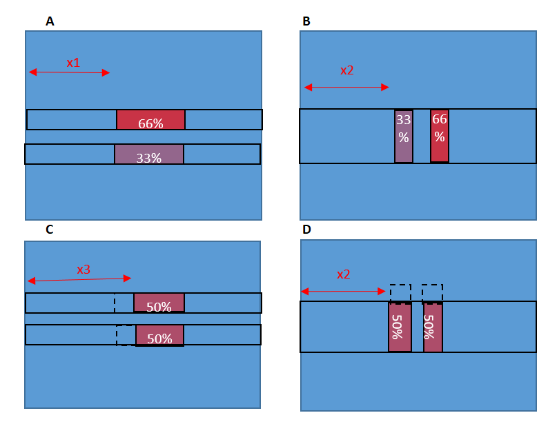
Tim Lohmann, Director at WHP, wrote an article in the ICE Forensic Engineering Journal explaining that the moments experienced by plant (through their typical construction activity) can cause an imbalance of loading. When these moments are perpendicular to the direction of the tracks, it can lead to up to 66% of the load being transferred through a single track. When the moments are in the same axis as the track direction, they can lead to a 33% reduction of effective track bearing area to due to the Meyerhof principles.
These principles are demonstrated in the figure below, for more information the article can be read by clicking ‘download’ below.
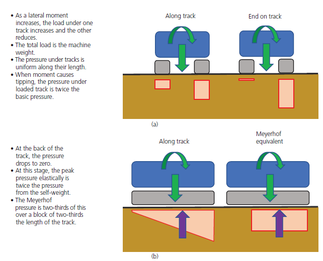
Because the slab I was assessing was one-way spanning, I had to consider both cases (a) and (b) above for the plant sat parallel and perpendicular to the slab direction. The four cases considered are in the diagram below. To find the max bending moment, the plant has been modelled at the mid span of the slab.
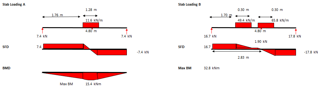
Step 2 – Calculate max SF and BM due to plant loading
The maximum bending moment and shear should then be calculated for each of the 4 combinations shown above. The SFD and BMD for cases (A) and (B) above are below.
Note – Ensure that the span you select is the maximum slab span anywhere on the floor you are assessing, as this is where the maximum BM will develop.
Note – The loading due to the plant should still not be factored.
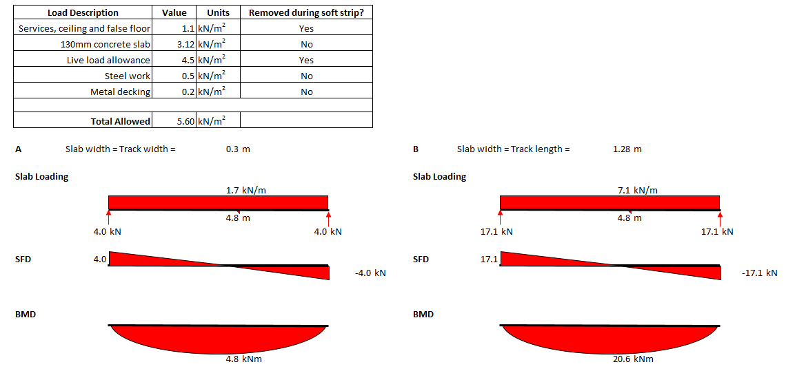
Step 3 – Calculate Max SF and BM due to slab design loading
Using the design loads for the slab (5.6kN/m2 as determined from demo spec), the maximum SF and BM that the slab has been designed to withstand can be calculated. Below are the max SF and BM for cases (A) and (B) above. The 5.6kN/m2 pressure has been multiplied by the width of the one-way spanning slab being assessed which is a track width for case (A) and a track length for case (B).
When compared to the max BM due to the plant in step 2, you can see that the SF or BM due to the design loads is significantly less than the SF and BM developed by the plant loading. If, when checked, it is found that these BM and SF are greater than those developed due to the plant, the assessor could safely say that the slab does have capacity for the plant.
Check 3 – Slab Section Analysis
If check 2 failed then the checker should check the section properties of the slab for capacity against the max SF and BM developed in the slab due to the combination of plant loading, slab self-weight and any other loads that may not be removed during the soft strip. Whilst the plant is positioned at the mid-span, the max BM will be at the mid-span.
Note – For this check the loads should be factored.
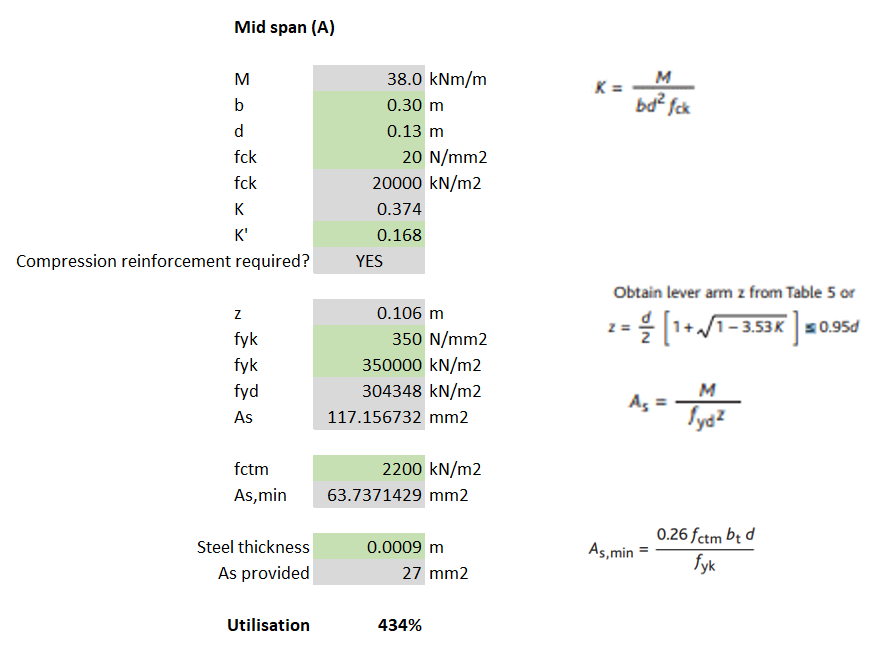
For my example, I calculated that for loading case (A) the max BM was 38kNm and then used EC2 to determine the steel reinforcement required. Because the slabs I was analysing were 130mm deep composite (steel deck) slabs, the 0.9mm thickness of the steel deck can be assumed to work as the tensile reinforcement.
Note – The yield stress of steel deck is unlikely to be the same as that for structural rebar (500N/mm2). I found it ranged between 280-350N/mm2 but check the manufacturer’s technical literature. The assessor should also check that the steel deck allows for sufficient bonding with the concrete for it to act compositely (normally achieved with dimples in the steel and shear studs).
A fundamental part of the check requires the slab (section) width to be considered. I noticed that when I considered load cases (A) and (C), where the slab width = track width = 0.3m, the section did not have sufficient bending resistance (failed by 334%) – see calculations below.
Check 4 – Assume load dissipates at 30 degrees
The assumption I had made from the very beginning was that, because the slab was one-way spanning, it was only the width of slab that was being loaded that could provide any resistance to bending/shear. However, according to BS8110-1, similarly to the way a concrete beam without shear links will normally fail on a plane inclined at an angle of about 30° to the horizontal, it can also be assumed that even a one-way spanning slab will utilise the strength of the surrounding slab, at an angle of 30 degrees.
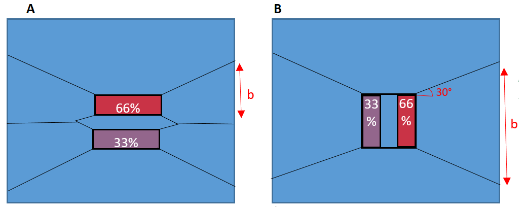
Using the principle described above, a new b (slab width) can be determined which can be inputted into the same section analysis conducted in Check 3. For load case (A), I calculated that at the slab support, the slab width was now 1.72m. This new slab width allowed me to calculate that the slab did have sufficient tensile steel.

Note – The issue with utilising this 30 degree spread is that the same checks should be conducted with the plant moved from mid-span to close to the supports. As the plant is placed closer to the support, the max BM will reduce but so will the effective width of the slab (due to the 30 degree spread).
Additional checks required
- Whilst max bending occurs whilst the plant is at the mid-span, max SF occurs when the plant is closest to the slab support, this should be modelled to check shear capacity and punching shear.
- If check 4 (the 30 degree spread) is conducted, checks should be conducted for all 4 load combinations with both the plant at mid-span and close to the supports.
- If the slab is continuous, checks for tensile reinforcement in the top of the slab to deal with hogging should also be conducted.
Summary
When working for a design consultancy, the efficiency with which we carry out these kind of checks is what makes the company the most money. This post demonstrates a hierarchy of checks that can be used, from most basic to more complex until I reached the stage where my check passed. Whilst the labour intensive check 4 gives the highest chance of a check passing, a quick check might show that the simpler checks 1 or 2 might also pass (and take a fraction of the time to complete).
If even check 4 fails then FE analysis may be required. Otherwise it might be time to tell the contractor that they either need to downsize their plant, or back-prop their slabs.
RMD Megashors: Failing by over 30%
Project: Fulham Riverside.
Context: RC framed multi storey building. Constructed. Columns needed to be replaced. This required temporary propping. Propping designed by external company consisting of RMD Megashors. The consultancy I’m working for were asked to check the scheme.
Event: We identified that the Megashors were inadequate for the loads. Failing by over 30%. The external temporary works designers had calculated the prop loading correctly, however they used an incorrect prop capacity. The capacities used were taken from an out of date datasheet.

A few years ago, the published capacities of RMD Megashors were significantly reduced. This occurred because one of the manufacturers had used an inferior grade of steel for a period of time. You can see from the diagrams below, taken from the technical literature from 2009 and 2017, that for a 3.5m effective length, the capacity has been downgraded by nearly 250kN!
Interestingly, the external temporary works designer knew about this however he was led to believe by his supplier that the RMD props that were being provided to him were of the higher grade. However, when asked, the supplier was not able to confirm this with documentation.

To compound the issue, when RMD originally published this, they announced that they had no method of identification (e.g. batch number or serial number) on the props, so determining the age of a prop and therefore which grade of steel is near impossible. This is why they took the huge commercial decision to downrate all of their Megashors. I guess it could be easier for a supplier as they would know when they bought their props, rather than RMD who I’d assume have a floating stock that is regularly replenished.
It is also interesting to note that the old spec allows for 50m/s wind as a horizontal load, but the new one doesn’t allow for any.
Lessons Learnt: When using RMD megashors, ensure that you are using the latest technical datasheet. If a supplier says that their grade is of superior grade, then the onus is on them to prove this.
The 2017 Megashore datasheet can be found here so you don’t get caught out although this demonstrates that it’s always worth checking to see if there’s a newer version!
“The Enemy That Kills You, Doesn’t Look Like You”
Read time: 5 minutes.
This morning was the ICE Strategy Session: Covid-19, Artificial Intelligence, and the future of the Civil Engineer. During the session, chaired by Rachel Skinner, Prof. Richard Susskind spoke about how AI and ‘the future’ might affect industries. His thoughts then provoked discussion amongst a board of construction industry experts.
Richard’s presentation focused on several key themes which I’ll summarise below:
The Mind Set
Richard explained that if, as an industry, we don’t want to be left behind, we need to change the way we approach problem solving. We shouldn’t be thinking about how we can do what we currently do faster, better or cheaper but change what we do all together to achieve the end goal.
An example Richard gave was the decline of the rail industry in the US. He suggested that their decline can be attributed to the rail industry’s inability to comprehend that they weren’t in the ‘rail business’, they were in the ‘transportation business’, and the customer didn’t care how they got there. Another example was given where the MD of Black & Decker explained to new employees that they weren’t in the ‘selling drills’ business, but in the hole making business, and if they find a better way to help customers make holes in walls that doesn’t involve a drill, then they need to adapt, quickly. The focus should be outcome above all else.
The Disrupter
The discussion then moved on to, “well ok, so who is it going to be that shakes things up”. After the CEO’s of several international construction firms (Balfour, WSP and others) discussed how we might adapt as civil engineers, Richard suggested that “the enemy that kills you, doesn’t look like you”. He went on to explain that whilst we might be able to disrupt and innovate internally, this is typically a very hard thing to do and usually it’s external people/companies who really disrupt industries.
So who might these disrupters be? Richard suggested that with the development of AI, data is king, and so it might be data analysts and scientists, not civil engineers, who create this disruption and lead innovation in construction. Mark Naysmith, CEO of WSP, supported this theory when he explained that as a consultancy, they’re employing more and more graduates with computer science degrees and even creative degrees such as art and music. Mark didn’t say if this meant he was consequently employing less engineers, I expect not, but perhaps this is us conceding as an industry that we, with all of our structural theory, might not be all of the solution to the problem. Those that don’t embrace this might be left behind.
Something that wasn’t mentioned in the strategy session, but I think reflects the sentiment, is what Dominic Cummings was trying to do in No. 10. We are familiar with the news that rather than employing civil servants and staff with politics degrees, he was employing data analysts and computer scientists to help run the government. Now, the success of his strategy would be a contentious debate, but to me the parallels are stark as we see an industry (politics) realising that the disrupter (the innovator) might not look like a politician.
My Opinion
It’s my opinion that the civil engineer, and what we design and build, will remain the solution to the outcomes required by society for at least the next 100 years. Whether that being transport infrastructure to enable trade and movement, energy infrastructure to power our homes or the high rise buildings to home us where space is a commodity. However, the longer we wait as an industry to ‘self-disrupt’ and innovate, the less control we’ll have over an industry that we regards as ‘ours’. This has already been witnessed with the modernisation of project management. The Bragg and many other reports of the 80s/90s that reviewed the technical and commercial practices of the civil engineer, saw the engineer’s remit transfer to project managers, quantity surveyors and schedulers. It’s my opinion that the longer we wait to self-disrupt, the higher the chances of what remit remains (such as risk management, construction sequencing, design and quality assurance) could become the remit of yet another specialist, perhaps data analysts and computer scientists.
Further Reading:
The session was recorded and should be available on the ICE’s website in a couple of days.
The board members were:
Prof. Richard Susskind OBE: A British author, speaker, and independent adviser to international professional firms and national governments, specifically on the use of AI.
Mark Neysmith: CEO of WSP UK and a member of the Global Leadership Team.
Simon Adam: Head of commercial for Crossrail 2.
Stephen Tarr: Managing Director of Balfour Beatty.
Suzannah Nichol: CEO of Build UK.
Chris Young: CEO of Tony Gee.
Preloading your backprops for maximum load distribution
Read time: 10 mins.
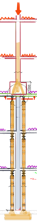
One of my first tasks on Phase 3 has been to develop a temporary works solution to support the demolition of the roof (RF1) and 3 levels (L01, L02 and L03) of suspended concrete slabs of the Coronet Theatre in Elephant and Castle. In order to demolish these elements, an 8 tonne excavator will be lifted onto L03 and break RF1; once completed the props on L02 will be removed and the plant will be lifted to L02 so that L03 can be demolished and so on.

Specifically, I have designed a back propping system to transfer demolition loads (plant and demolition debris) from suspended concrete slabs to the ground. Back propping is required because a cursory check tells us that the concrete slabs were designed for imposed loads much lower than those imposed by an 8 tonne excavator and up to 0.5m of demolition debris.
As you can see from the diagram, the loads from the working platform will be transferred directly to the ground, however, in the development of this solution I considered transferring the loads to L02 and L01 only to save the Client the use of the costly Titan props used on the ground floor. In doing this I used the principles taught to us in applied structures (by JAM I think?) that were summarised by Pallett (2016) typically used when designing falsework, see diagram below.
Pallett tells us that with two levels of back propping, I could distribute 65% of the demolition works loads onto L03, 23% to L02 and 12% to L01. With just one level of back-propping this distribution would be 70% to L03 and 30% to L02.
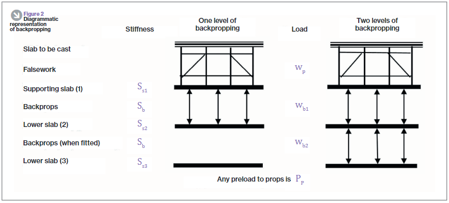
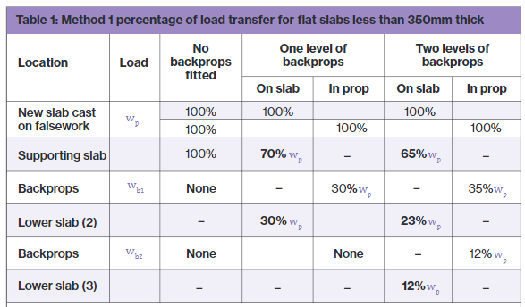
One might expect that with the use of a rigid prop, deflection in the top slab would equal deflection in the supporting slab as shown in the diagram below. If this was true then the load on the top slab would be split equally between the top and supported slab, 50% of the load to each. In essence, the two slabs become one member with the slabs acting as flanges and the props acting as webs. So why does Pallett tell us that the loads would be distributed 70/30, not 50/50?

The answer is because the props too act elastically and shorten when exerted to the axial load as required by d=PL/AE. If the member can’t shorten, then the load can’t be transferred. Instead, the interaction between the slabs and props looks much more like that in the diagram below. There it can be seen that the deflection for the top slab is greater than that of the supporting slab.

Preload your backprops!
Unfortunately it was still assessed that even 65% of the load imposed by the demolition works would be too great for the suspended slabs and so I looked for other solutions, determined not to use the expensive lower level Titan props. I had seen that Pallett released a further article in TheStructuralEngineer in 2017 that suggested that backprops could be pre-loaded, an interesting concept that I thought I’d look into.
Think about how you install a prop, typically you stand it between the supporting and supported slab and begin to twist the collar, extending the prop until it is firmly wedged in place. Well what would happen if you kept twisting the collar, perhaps using a sledge hammer or using a long spanner as a lever? The answer is that the top slab would start to hog and the bottom slab would begin to sag. It turns out that by doing this we can actually achieve the conditions so that the load can be shared equally between slabs, 50% each for a 2 slab system or 33% each to a 3 slab system as is the case with my problem in Elephant and Castle.
How to design back-propping
It’s all very well knowing that by exerting a load on the supporting and supported slab by preloading your backprops you can distribute loads imposed on the supported slab equally, but how can this be designed? It can be designed by the basic application of PL/AE.
Take the following example:
E: Prop material stiffness = 69 GPa. The Youngs modulus value for aluminum.
A: Prop section area of material = 0.00259m2. Taken from manufacturer’s technical literature.
L: Length of prop = 2.982m (distance between slabs).
P/d: The force per mm extension, kN/mm.
and rearrange the equation so that P/d = AE/L. We can then work out that for every 1mm the prop is extended, it exerts a force of 60kN. If we also know from the technical literature that one thread (turn) equates to an increase in prop length of 2mm, the instruction to site in order to exert 30kN to the supporting and supported slab each (60kN total), would be to give the collar half a turn. Tests carried out as part of the European Concrete Building Project (ECBP) found that by using this method with a prop system, you could practically apply an upwards UDL of 0.5kN/m2 on the bottom of a slab.
Of course, if using this method to equally distribute loads there are a few things that need checking:
- Has the supported slab got sufficient reinforcement to tolerate the hogging due to the applied upwards force; a typical concrete slab would have maximum sagging and minimal hogging reinforcement at mid-span.
- Are the loads acting on the supporting slab (self weight, load imposed by preloading props, shared load from supported slab, other imposed loads) within the capacity of the slab.
- As the axial force in your props increases so does the likelihood that they will buckle, they might need restraining with ledger frames.
The ECBP found that this method was difficult to implement with thin slabs because of their flexible nature leading to the tendency to transfer load between adjacent props as one is tightened up.
In all there’s nothing ground breaking here but a bit of applied engineering to distribute that little bit more load between your slabs, it might just make the difference.
References:
- Temporary Works Toolkit. Part 4: An introduction to backpropping flat slabs. Pallett, TheStructuralEngineer (2016)
- Temporary Works Toolkit. Part 6: Backpropping flat slabs. Pallett, TheStructuralEngineer (2017)
Think twice before paying for an ‘expert opinion’
This is just a short post but I thought it was interesting.
Whilst researching into UXOs and the effectiveness of qualitative vs quantitive risk assessments I came across an interesting study. In the study the researchers asked 25 experts in the UXO industry to make a series of risk assessments, typically based on the probability of a UXO detonating in certain scenarios (e.g. striking a UXO with the back hoe of an excavator or being played with by children).
The study essentially concluded that when you pay an expert for their opinion, at least in this field, you might as well not bother. The figure below shows the results of part of the study where each fitted cumulative distribution function (CDF) represents the assessed probability of a UXO detonating by a different expert. The report summarises that “In three of the six scenarios, the divergence was so great that the average of all the expert probability distributions was statistically indistinguishable from a uniform (0, 1) distribution—suggesting that the sum of expert opinion provides no information at all about the explosion risk.”. This basically means that the average of their results said the probability of explosion was equally likely to be 0% as it was 100% (with a low confidence interval), not necessarily very useful information! My initial thoughts are that where data can be acquired, assessments should be made quantitively where possible.
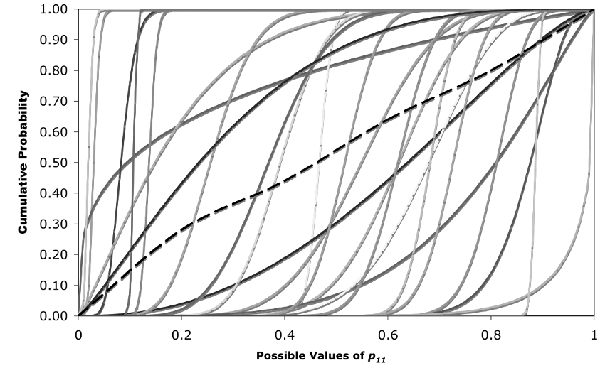
The solid curves are the CDFs of the individual experts, and the dashed curve represents the CDF of the mean explosion probabilities estimated by the experts. The horizontal axis indicates the probability of explosion. The vertical axis represents the cumulative probability that the chance of explosion is less than or equal to the corresponding horizontal axis value.
The full report can be accessed here: https://onlinelibrary.wiley.com/doi/abs/10.1111/j.1539-6924.2008.01068.x
