Archive
Future Phase 3 (Civil) placement in London
Hi everyone, not a technical blog, just passing on contact details of my Phase 3 in case anybody wants to go there next year.
I have been working for Wentworth House Partnership (WHP), who are part of the Keltbray Group. Keltbray are a specialist contractor, traditionally in demolition, but have expanded into piling, asbestos removal and rail amongst other things. They have recently set up a structures business (concrete framing) in its own right, and have just won the contract to build Battersea Phase 3A.
WHP are the design consultancy for Keltbray, but do about 25% of their work for external companies. Most of the work is for temporary works, which means fast paced designs and a very varied experience. I cannot say if this is better or worse than a permanent works design office as I’ve not worked in one, but it has suited me. More hand calcs, less importance put on things being used to 100% of their capacity, as long as it works and is 80%+ efficient it is usually good enough.
I have designed in steel, timber, concrete and lots of design work using scaffolding and other off-the-shelf solutions. Some geo too; there is a geo ‘department’ (4 guys) but I have only really dipped my toes into the water there and done the simple analysis. All in there about 45 engineers and technicians in the office.
The three directors are all Fellows of the ICE and IStructE, and two are active ICE reviewers. They know what you need to pass CPR, and are a really good source of advice. They arrange weekly CPD in house over a free lunch and at any one time probably have about 5 or 6 of their own staff going through the Chartership process.
Stuart Marchand (the managing director of WHP) was a founding member of the temporary works forum and a previous chairman. Tim Lohmann (another director at WHP) is the current chairman, and the final director (Stuart Vaughan) probably will be chairman in the future. My point is that WHP is a very good place to learn about temporary works, which I think share many characteristics to a lot of military engineering solutions.
The office is in Esher, so really handy if you live in The Keep. If not it is a 24 minute train ride from Vauxhall. The full address is: Wentworth House Partnership St Andrew’s House Portsmouth Road Esher KT10 9TA.
If you’re interested, email the directors and mention the PET Course, they have hosted myself and Fred Kiddie before me so they know what the course is about.
director@wentworth-house.co.uk
Demolition Engineering – Load Testing
I am conducting my Phase 3 at Wentworth House Partnership (WHP) who are the in house design office for Keltbray Group (KG), a specialist contractor with varying business units from demolition, through piling, to rail. About 75% of WHPs workload is from KG, the remainder is for non-competitors. Demolition is KGs biggest sector, hence the majority of WHP’s work, and my work to date, is to do with demolition.
The usual method of demolition in urban areas is top down demolition, which is essentially construction in reverse. Due to the construction techniques that were prevalent in the post war years, the majority of demolition is currently that of multi-storey reinforced concrete buildings.
To facilitate this form of demolition, plant is lifted to the top floor of the building and methodically demolishes the building one floor at a time, usually using the lift shafts as a drop zone for debris. The larger the machine is, the quicker (and therefore generally cheaper) the demolition process is.
The loads imposed on a structure during demolition are generally larger than the building was designed to accommodate. The loads come from demolition debris, plant used and changes in load paths by removing structural elements.
Removing structural elements and using heavy plant on suspended floors presents two main engineering challenges; determining the load capacity of the floor plates to size the machine that can be used, and ensuring that the building remains stable during demolition. This blog will outline the various methods that I have used for determining the capacity of the floors.
Option 1 – Allowable floor loads.
If the original purpose of the building and the year of construction are known, the relevant floor loading can be found from the codes which were in force at that time of construction. This is clearly the simplest approach, but it has two main drawbacks. Firstly, you have to ensure that no modifications have been made to the building, usually requiring time consuming opening up works. Secondly it is very conservative, resulting in either lots of back propping to mobilise the capacity of several floors, or smaller machines being used resulting in inefficient demolition. Engineering judgement allows the floor capacity to be increased by calculating the weight of non-structural finishes, partition walls, plant, etc., which will be removed prior to demolition. Additional capacity can be proven through knowledge of the safety factors that were used, under the BS factors were 1.4 for dead loads and 1.6 for live loads. Even with both of these methods, this option is still very conservative.
Option 2 – Back-analysis of structure.
It is possible to assess the floor to current standards to determine the capacity. However this relies on either original drawings existing, or time consuming opening up works being conducted. Currently I have only worked on one project where some drawings existed and assumptions were made (and communicated to the client) based on these. On other jobs, I have had to use the code of the period of construction to identify the minimum area of steel, cover, material properties, etc., and then use current codes to design based on this. Again, this is a very conservative technique.
Option 3 – Load Testing.
It is acknowledged that the design capacity of a structure is a lower bound value for the strength and that there may well be significant additional strength as a consequence of rational design, conservative assumptions in design and material strength issues. Large scale load testing can be used in order to establish what this additional strength is.
There are no standards for the structural testing of buildings during demolition. The approach that I have used is to select bays that are to be demolished and to test these to a load that represents the applied load from the demolition, with a suitable factor of safety. The factors applied to the load are 2.5 for flexural testing and 3.0 for shear testing.
Generally there are 5 common failure mechanisms for reinforced concrete buildings; flexural, beam shear, punching shear, buckling and progressive collapse. My experience suggests that most demolition projects involve flat slabs, built before the lessons were learnt from Ronan Point, so punching shear and the potential for disproportionate collapse are usually the limiting factors.
When I have specified load testing, I have used the approach shown in Figure 1. This consists of 3 separate types of test, all conducted in separate bays, selected for their uniformity across the project.
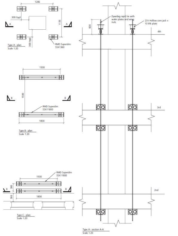
Figure 1. Load Testing Arrangements.
All tests follow the same basic set up; jacks are positioned on beams (generally sections on RMD super slim soldiers) which are tied to a number of floors below to achieve the required mass to jack against. The jacks can be propped from above instead of tied from below, but the props require large sections to resist buckling when compared to a 15mm diameter bar which is rated to 9t in tension. The specifics of each test is below:
Test Type A:
This is designed to test the capacity of the concrete columns. The test checks punching shear at the column faces in order to ensure that the excavator does not punch through the slab at these points. Set up shown in Figure 2.
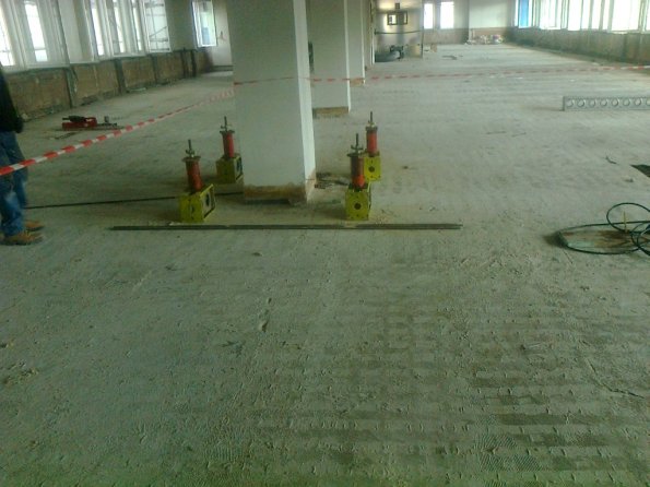
Figure 2. Test Type A.
Type B:
The Type B test is designed to test the capacity of the concrete slab and will take place at the point generating the largest moment and shear actions. The proposed testing will check flexural and shear strength in order to ensure the excavator does not fail the slab at these points.
Type C:
The Type C test is designed to test the capacity of the walls or edge columns. The proposed testing will check punching shear at the edge columns and the face of the wall in order to ensure that the excavator does not punch through the slab at these points.
Outcome
Generally option 1 and 2 are conducted, and unless a minimum of 8t machine (actually 9.6t with demolition equipment attached) is able to be used on the slab, load testing is requested. Load testing is time consuming, but it can generally be conducted during soft strip and has the potential of allowing a far larger machine to be used, saving much time in the process. When all three options have been used and the required capacity has not been achieved, the slab will be back-propped to a number of floors below to achieve the required capacity. Back-propping is time consuming and resource intense, so the fewer levels of back propping the better. As a matter of course, KG back-prop at least one level around all columns to mitigate punching shear.
Reflection
Load tests generally result in the floor having a capacity of circa 300% of the design value. Some of this accounted for by rational design, conservative assumptions in design and material strength, as stated earlier. I have identified the following additional reasons.
‘Non-structural’ screed
Most slabs have 50mm of screed on top. This is taken into account in the self-weight, but is neglected from structural calculations. In reality, screed does possess significant compressive strength. When the compressive region of the slab is on the top, which is usually the case, this screed increases the lever arm of the slab, increasing the capacity.
Ultimate limit state
Demolition engineering is not concerned with serviceability limit states, although there are exceptions, such as partial demolitions. Cracking in the tension zone is not a concern if the building is being demolished. This allows far greater loads to be applied whilst maintaining structural stability.
If anyone has any extra theories as to why structures are so much stronger than their design suggests then I would be interested to hear them.
Can you under-sling a DROPS rack?
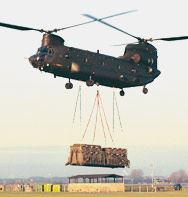
I have been asked to look into designing a system that would allow a lorry loaded with supplies to pull up under a crane, and have all its stores unloaded in a single lift. This could range from a full load of rebar, to a single machine, weighing up to 15t.
The purpose is to speed up unloading so that the crane can get on with construction, and to remove the lorry from site sooner, as logistics and unloading spaces are tight.
Does anyone know if you can under-sling a DROPS rack? I am relatively sure that the APFB comes on a DROPS rack, and clearly that can be under slung, but I am not sure of the maximum load that rack could carry like this (ignoring the limitation of the hook, the crane is perfectly capable of the loads required.)
I have trawled through the BA Battlebox logistic pamphlets but with no luck. I know that the DROPS can carry 15t and has a self weight of 1.5t, but I do not know if this capacity would reduce if lifted by a crane and not loaded onto a lorry.
Any suggestions?
The Rising Factory
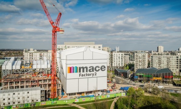
Figure 1. East Village, Stratford.
Summary
As part of the handover between Skanska and Mace, all Battersea phase 2 staff are getting various presentations from Mace to tempt us to join them. Yesterday we had a presentation which featured a different Mace project, East Village in London, which is being constructed in a really innovative way, and I thought I would share. I must stress that I have not worked on, visited (I am trying to arrange this) or even seen this site, and that my knowledge is restricted to what is contained in here. They are using jump forming of sorts, but instead of just producing a concrete core, they are raising the ‘rising factory’ to reveal a completed floor of the building. Interestingly, all lifting is done via gantry cranes inside the rising factory, utilising the riser shafts within the building. This negates the need for tower cranes (NB the tower crane in Figure 1 is for the surrounding construction) and eliminates down time due to high wind. The weatherproof factory environment also allows for safer construction year round.
Background
The jump form and slip form systems are well established, but what emerges is the raw core of a building with all the remaining elements still to be constructed, with all the associated programme disadvantages. The ‘rising factory’ is a 10 storey high enclosure inside which the construction of a complete multi-storey building takes place over 5 construction levels. What emerges as the factory is jacked up on its weekly cycle is a level of newly constructed building which from the outside is complete and just requires finishes to be applied internally. Cranes (including vehicle container offloading), storage and welfare facilities needed for the construction activities are all within the enclosure and varying types of activities happen at each level from construction of the structural columns and slabs at the top to completion and sealing of the cladding at the lowest level. A jacking system is permanently attached to the factory columns and the jacks engage with the support brackets when the factory makes its weekly lift. The factory facilitates the construction of a 30-storey building with a cycle of a week per floor, giving large programme and site health and safety benefits. These benefits are significant for all parties.
Operation
In 2016 Dorman Long Technology (DLT) were awarded the contract by Mace to supply two pinned climbing jack systems for the construction of twin residential towers at their East Village Development. The project aims to construct two high-rise residential towers using pre-cast concrete construction. The ‘rising factory’ concept is used to create a waterproof factory environment for construction and fit out of each floor. The scheme uses a temporary steel rising factory building erected over the top of each residential tower during construction, which contains two 15t gantry cranes. After each floor has been constructed the temporary steel rising factory is lifted by 3.3m by the 4 x DL-CP250 pinned climbing jacks which remain static, but lifts the climbing bar connected to the rising factory, allowing the next floor to be built.
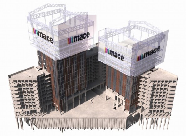
Figure 2. Image from 4D modelling.
The first jump of the rising factory was completed successfully in Feb 2017. During this jump the factory was raised 6.6m – twice the intended standard jump distance of 3.3m. This was to allow completion of assembly & cladding of the factory structure and construction of the next two floors of the 30 storey tower. Figure 3 and Figure 4 show the factory before and after the jump. The factory, which in this partial completed state weighed 565t, was lifted using four 250t DL-CP250 pinned climbing jacks controlled by DL-P40 computer control system, as shown in Figure 5.

Figure 3. Tower before jump.

Figure 4. Tower after jump.
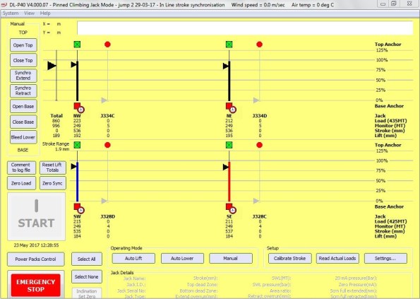
Figure 5. DL-P40 computer control system during jump
During construction of towers, the weight of the rising factory is supported by four hydraulically operated pins (Figure 7) which connect it to the high-rise building via four jump brackets, one fitted to each corner column of the building. All vertical and horizontal loads from the rising factory are transferred to the building via these pins. During factory operation the pinned climbing jacks (Figure 6) and climbing bars are not subjected to any imposed loads. During the jacking of the factory the pins are hydraulically withdrawn and the pinned climbing jacks lift the climbing bars which are fitted to the rising factory. The pinned climbing jacks are each mounted on top of a jump bracket via a pair of link plates.

Figure 6. DL-CP250 Pinned Climbing Jack.

Figure 7. Hydraulically operated pin.
Conclusions
This method appears to offer huge benefits to construction, but like many innovative techniques, it must be chosen early in the design stage. The footprint of the building must not be too big, and the risers must be sufficiently large and appropriately placed to allow all of the required materials to be lifted through them. Although this case study uses pre-cast concrete elements (saving further time) I cannot see why it could not be adapted to contain a concrete pump and use cast-in-situ construction if desired. The benefits are obvious, and although there are numerous projects where this construction method will not be suitable, I expect to see an increase in the use of rising factories.
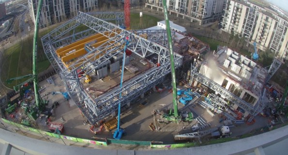
Figure 8. The rising factory from above.
The dangers of storing piling casings upright
Just a quick blog to warn about the dangers of storing piling casings upright, something which is done at BPS as space is tight, and I am sure is often the case elsewhere too.
When excavating down to the pile to construct pile caps, the reinforcement cage was clearly damaged on two adjacent piles, as shown in Figure 1 and Figure 2. After a brief investigation, it was concluded that the damage was probably caused by screwing a casing into the ground as indicated in Figure 3.
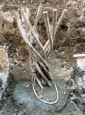
Figure 1. Damaged reinforcement cage 1.

Figure 2. Damaged reinforcement cage 2.
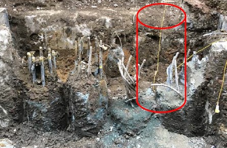
Figure 3. Assessed cause of damage.
What is going to happen now?
- Mitchellsons to break down the pile to sound steel and concrete which could be deep, attach couplers and extension bars and add additional shear reinforcing rings if required;
- Mitchellsons to then build the pile back up.
Impacts to Bauer (Piling Contractor)
- Repair and re‐work charges to be expected from Mitchellsons;
- Could cost Bauer up to £10,000 or £15,000 on this pile! There could be other piles where this has happened, not all are excavated yet.
Preventative Action
- Avoid screwing casings into the platform for storage as much as possible;
- If possible lay casings on the platform;
- If needed to store casings vertically, before screwing the casing ask the setting out engineer if the location is free of previously completed piles;
- The engineer will specifically locate clear areas and mark them out, or place casings into new pile locations to start to form the next pile.
SUPERLATCH – An innovation in piling safety and a time saver
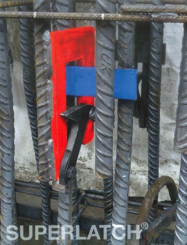
Figure 1: Superlatch connection system.
Today I used SUPERLATCH to splice the pile reinforcement cages for the first time, and I thought that the overall system is interesting and worthy of a blog. The inventor (Steve Render) was here as the system is in its infancy, so I had a good opportunity to ask a few questions and to get a brochure from him as well.
Superlatch is a highly efficient means of connecting spliced reinforcement cages during the construction of rotary bored piles, and I was assured that it can be used in CFA and diaphragm walls too. It has two main aims, to save time, and to increase safety. I will cover these separately below:
Safety
Traditionally the connections between sections of reinforcement cage have consisted of multiple shackles or u-bolts which are secured by the contractor between the piles. This practice requires that the operatives reach through the gaps in the cages with their hands or even whole arms, whilst the lower cages are suspended on the casing with temporary supports, and the top cage is suspended by a crane. Although this process has been used at BPS for all piles so far without incident, if either of these cages were to move, the arm / hand would be at serious risk. Superlatch is welded to the cage off-site during cage construction, and when the cages are lowered onto the preceding cage, the latch mechanism (covered later) automatically secures the connection with no need for any operatives to reach through the cage. If the cage needs to be dismantled for any reason, there is a release tool (Figure 2) which again does not require an operative to reach through the cage.

Figure 2: Release Tool
Time
In theory, not having to manually splice the cages clearly saves time, however so far my experience of Superlatch (one pile consisting of 5 cages and 4 splices) is that it is slower, although I am confident that it will soon speed up. The cages which it is being used to splice are formed of 44no 40mm diameter bars, spaced equally in pairs. There pairs are welded together in places, the uppermost of which is approximately 1.2m from the end. This results in some pairs having gaps between them at the end, as shown in Figure 3.
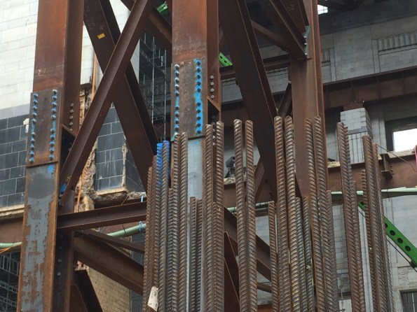
Figure 3: Gaps in paired bars.
When lowered, the Superlatch in the upper cage sticks into the lower cage like a fin, as seen in Figure 4. These fins need to be located between the pairs of bars, but it has proved difficult to achieve this, often resulting in many lowers and raises of the cage before it is in the correct position. I have suggested that the pairs of bars are spot welded at the top to mitigate this problem – but no welding of the cages is allowed on site, and attempts with tie wires proved insufficient. The fabricator will be contacted and asked to do this weld at the top, which should improve the time taken on piles where the cages are yet to be delivered. Clearly this will not be an issue when single bars are used. I expect this system to save approximately 10-15 minutes per splice in the near future, resulting in a considerable saving of 40-60 minutes per pile, as well as increasing safety.

Figure 4: Multiple latches per splice protrude like fins into the inside of the cage.
How does it work?

Figure 5: Superlatch Mechanism.

Figure 6: Mechanism in position.
As can be seen in Figure 5 and Figure 6, Superlatch works with a simple spring loaded latch, which is lowered onto a receiving band (shown in yellow on Figure 7) on the cage below. This bands can be substituted with a plate for a diaphragm wall. There must be a minimum of 2 latches per splice, today we had 3 for the lowest splice and 4 for the remainder, due to the load each splice would carry increasing up the length of the cage (the cages are suspended during the pour.) A range of sizes of Superlatch are available, with an individual load range of 1-6 tonne, so it can be suitable and efficient for small to large cages.
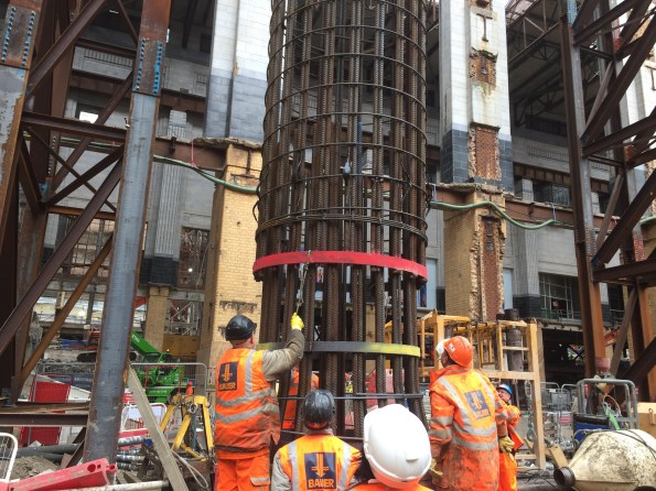
Figure 7: Lowering the cages together.
Conclusion
This system is undoubtedly safer, but in my experience of piling (admittedly limited to just 7 weeks) the risk which it mitigates has a very low likelihood already, and potentially does not need further mitigation. However, as a time saving product, I think that it is a really good option. Bauer and their cage fabricators have not used Superlatch before, and the operatives here and the fabricators at the yard are still learning the initial lessons of how to adapt their techniques and designs to maximise the potential benefits. With a little more experience in splicing cages in this way, coupled with an extra / repositioned weld when bars are in pairs, I think that the product will be a success.
I have added the Superlatch brochure here if anyone is interested, and I will reply in 1 to 2 weeks with an updated opinion of time savings once I have used it more and when the modified cages arrive.
How your Great Grandad built a Chimney.
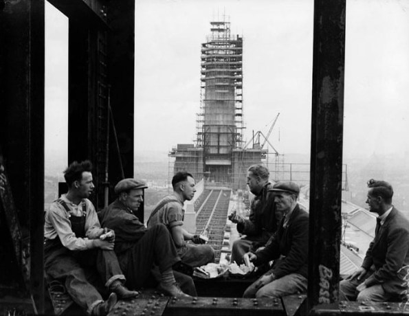
Figure 1: The original construction of Battersea Power Station’s chimneys.
English Heritage had many stipulations before planning permission was granted for the redevelopment of Battersea Power Station, a key one of which was the restoration of the iconic chimneys. These had to be built using the same methods as they were in the 1930s, which has led to some interesting issues during construction.
Jump forming over slip forming.
The original proposal was to slip form the main shaft of the chimney using a smooth form, and then go back and attach the ribs, which are mostly cosmetic and contain no reinforcement, afterwards as well as marking on the day joints (Figure 2.) However, the use of jump forming was enforced as this was used during the original build. This is where the formwork is lifted 1.22m (4 feet as per original design) every other day, building the chimney in a series of rings. This results in the horizontal rings, or day joints, as a by-product. The ribs are cast at the same time during jump forming. Having not been involved in slip forming I do not know if these ribs could be included in a slip form, could someone enlighten me? To ensure that there is an interlock between the pours, the top of the pour is sprayed down at the end of the day to remove the grout and expose the aggregate, allowing the next pour to bind to the previous one.

Figure 2: Original chimney, showing taper, day joints and ribs.
The taper.
As can be seen in Figure 2, the chimneys taper as they rise. This is achieved by using removable plywood panels within the outside formwork (Figure 3), which have a slight taper and are trimmed by 1.5mm per side per jump. They are sized to fit between each of the ribs. To make this small cut easier, there are 3 sets of panels, so after each form is used it is trimmed by 4.5mm on each side and introduced back into the cycle. The ribs themselves are a constant size throughout. As there are no ribs on the inside, the formwork is simpler and consists of metal sheets which can slide over each other to reduce in size.
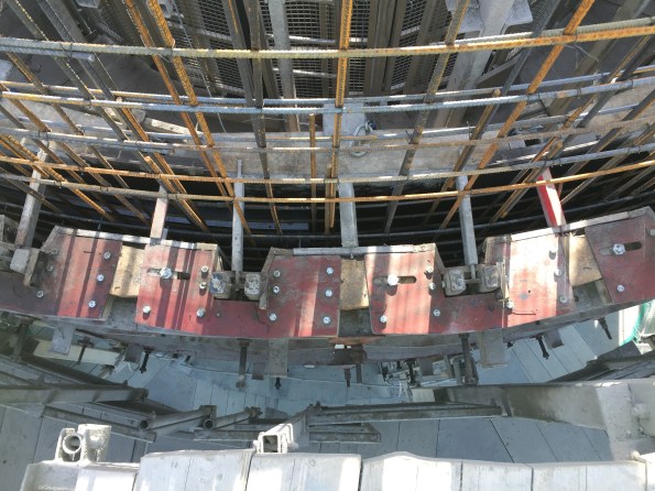
Figure 3: Formwork.
Concreting.
Due to the low quantities of concrete required per jump, a concrete pump was not suitable as more concrete would be required in the hose to achieve the height required than is actually needed in the formwork. Instead, there is a 600L hopper on mini train track installed within the hoist (Figure 4), which is filled from the onsite batching plant (which is purely for the chimneys and can only produce 300L per batch) via another hopper on a set of forks. The hopper is then pushed back into the hoist and ascends. At the top this hopper is used to fill 4 wheelbarrows, which are moved in a one way loop around the top of the chimney, pouring into the formwork via a wooden slide, before continuing around to be filled again. There are two wooden slides (Figure 5) which leap frog each other around the chimney, and despite the system being so low tech, it is remarkably efficient. The workforce of 7 (4 on wheelbarrows, 1 on the hopper / hoist, 1 with a vibrating poker and 1 supervisor / slide mover) quickly pour the 600L into place. Using this system they are now able to achieve 1 jump every 2 days.
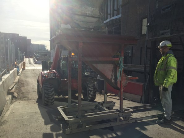
Figure 4: Hopper on tracks.
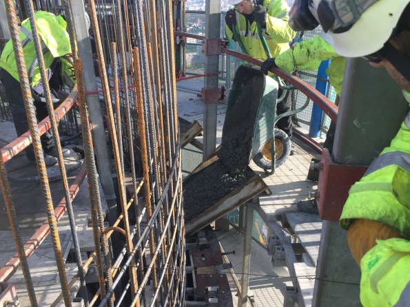
Figure 5: Wooden Slide.
Reinforcement.
This is shown in Figure 3 and Figure 5, and it consists of an inner and outer mesh which is constructed from straight bars every other day, in between pours.
Future use.
There are Halfen channels cast into the inside of the chimneys, as there are various fixtures being installed later on. All will have internal ladders for maintenance, one will have 5 flues for the various plant rooms across the development (so that the chimney will “smoke” once again) and 1 will contain a glass viewing platform in a lift which Willy Wonka himself would be proud of, as shown in Figure 6.
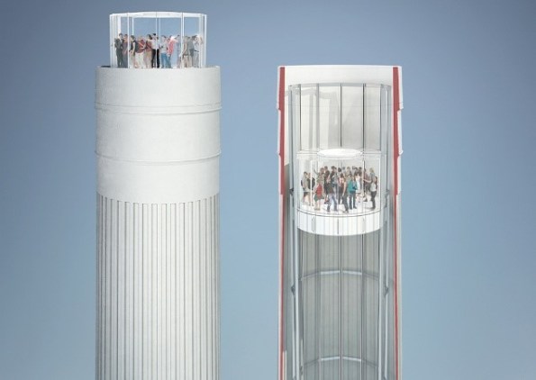
Figure 6. Glass Elevator in the North West Chimney
Summary.
I think that this construction method proves two main theories; keep things simple where possible, and that repetition will improve speed. Firstly, I think that there will always be a place for the simple, low tech solution in construction. Although simpler methods may not be as quick as more modern techniques, the potentially low set up cost and running costs, coupled with the speed at which they can commence, could often offer a more affordable solution. Clearly this may not be the case if the task is on the critical path where time is likely to be the main driver. Secondly, where things can be designed to be repetitive, they should be. There are a total of 4 chimneys to be restored, each requiring over 40 jumps. The overall process is becoming slicker each jump, and although the crew quickly reached the maximum allowed rate of 1 jump every 2 days, the total working hours to achieve this has reduced.
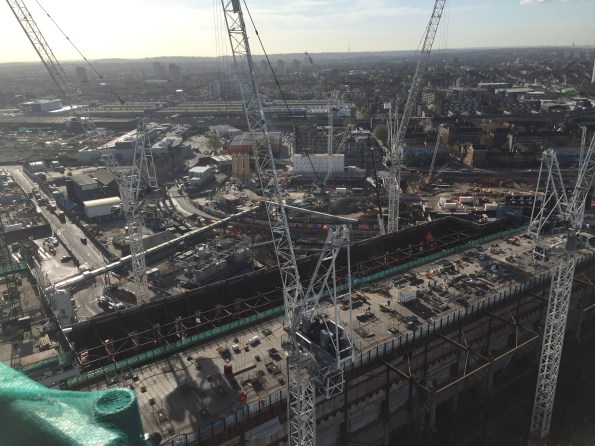
Figure 7: The view from the top (looking at the NLE.)
The chimneys are now finished, and a construction enquirer article has been written.
http://www.constructionenquirer.com/2017/06/05/two-year-rebuild-complete-of-battersea-chimneys/
Piling case pulling out reinforcement – Request for advice.
I am working on Phase 2 of the Battersea Power Station redevelopment, inside the power station itself. Within this I am managing the piling package inside the Boiler House, which in way of orientation is the main, central building of the power station, with the towers and chimney in the corners.
I have recently encountered my first issue, and although we have found a solution to allow construction to continue, we have not found the cause. I was wondering if anyone has any previous experience of this and knows the cause, so that hopefully I can prevent it happening again.
The design for this pile had the toe depth located in London clay, and as such the casing was used to seal into the clay, but no further, with the undrained strength of the clay allowing the rest of the bore to be drilled without the need for bentonite support. However, after over drilling beyond the London clay layer and into the aquifer below, and with the bentonite plant not yet operational, further casings had to be used to prevent the Thanet sands from collapsing into the bore. With this new depth a pile redesign was required, resulting in little more than a longer length of reinforcement cage needed, which was spliced on, and the concrete pour went without incident.
A total of 30m of casing was installed on this pile, far more than had been designed for, and it is when the casing extraction began that the issue arose. As the second section (3m) was extracted, the reinforcement cage rose with the casing. The cage had somehow become stuck in the casing and was being pulled out with the casings. Bauer (the piling contractor) were unable to push the casing back down, and after numerous attempts to rectify the situation, Bauer made the decision to remove the entire cage for the pile, and core through the existing pile to form the new one.
Unfortunately the first (top) splice joint in the reinforcement cage failed (it was not designed for tension with a load a wet concrete on it) during the casing extraction, and only the top cage (approximately 12m long) could be removed. After several hours of failing to dig out the cage (I believe the concrete was still too wet) it was left as is. Currently the dip to concrete is 7.3m from ground level and there is 8m of casing on, but lifted above the concrete.
It has been decided to backfill the void and to place a new pile either side, with a capping beam on top, rather than try to rectify this pile. Space allows for this and schedule is the driving factor, with this being put forward as the quickest solution.
Where I am after advice is what caused this to happen. Currently there are 2 possible options being discussed, but I am having difficulty accepting how either of them could have caused the issue. I have outlined the options and my thoughts on each below:
- The cage was simply caught on the teeth of the casing. The spacers should have kept the cage away from the teeth, and if this was the cause then I can struggle to see why only the top cage was caught. It would make more sense to me that the entire cage would be pulled up if it was caught on the teeth. Or am I missing something?
- Grout loss during the pour. If there was a large amount of grout loss then could the denser concrete and increased aggregate have simply jammed the cage into the casing? If this grout loss was towards the top then I can see how that could explain why it was only the top section which was jammed, but I fail to see how there could be grout loss inside a casing?
If anyone has any further information on either of these options, or has other theories to throw into the mix, then please get in touch. I have about 200 piles to go and would like it if the rest went more smoothly!
Phase 2 Placements
To all C’s,
The time is now upon us students in phase 1 to start looking for our placements. There are at least 7 of us staying in the UK, with the majority looking to work in London.
Do you know of any interesting projects coming up within your companies that would be good for us to jump on in March 17, or will there still be work on your sites which we could take over, and if so can you give us an outline of what that work would involve?
Finally, do you have any tips for finding placements other than scanning through Construction Enquirer which it currently our main point of reference. Any information would be greatly appreciated.
