Archive
Design Risk? Perhaps think twice or double-check…
I’ve delayed sharing this post as I was waiting for the completion of the investigation report however it looks like it will continue for some time. The information in blue italic text is taken from the draft incident report summary prepared by the safety team on site. I’ve also interspersed comments and pictures to aid understanding. This incident is a sharp reminder of design responsibility as we look to transition onto Phase 3 next month. At the heart of the incident is the combination of 5 issues:
- Incorrect design/design shortcuts
- “I’ve done this before/This is how we did it last time”
- Short notice change of plan on site
- Lack of communication between the site team
- The interface between unplanned or different activities on site
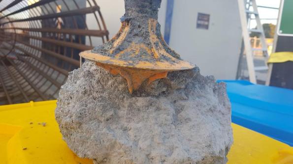
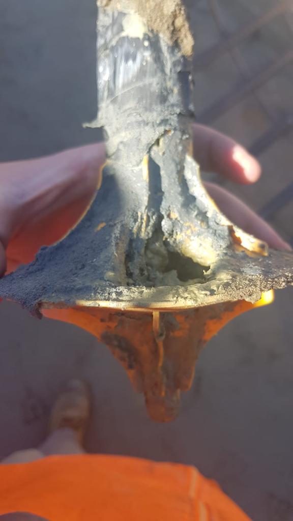
First, a few pictures to whet your appetite to read further…


Now the pictures have got your attention I thought I would share a little bit about the serious incident that happened at the pre-cast yard in September. The incident was classified as a 1P incident under the John Holland system. 1 = most serious (deadly consequence) P = potential (fortunately there were no injuries). The incident cost is valued at A$ 100,000
Executive Summary
John Holland has been engaged by Roads and Maritime Services (RMS) to construct a new bridge on the A1 Princes Highway over the Clyde River at Batemans Bay. The new bridge will improve access to Batemans Bay and surrounding areas, allow access for larger trucks, reduce traffic delays and improve the Kings and Princes Highways intersection
The project involves the upgrade of approximately 1.55km of Princes Highway between North Street and Kings Highway from predominantly two lanes to four lanes, two lanes in each direction. It includes a new 420m long bridge over the Clyde River, located to the north-west of the existing bridge. The bridge consists of a total of 168 segments currently being manufactured at the projects temporary precast facility located approximately six kilometres south of Mogo.
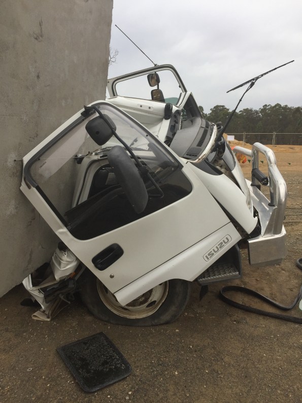
At 09:00 on Friday 20th, September 2019 a 250-tonne crawler crane lifted Segment P5-1U (the segment) off the transfer table and placed the segment on support pads. The segment weighed 95 – tonnes. The support pad arrangement consisted of three support points, two on one side and one on the opposite side, the pad on the single support point taking fifty percent of the load.
A section of the support pad arrangement is shown below: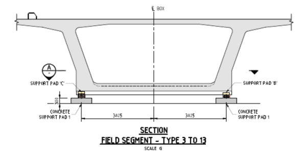
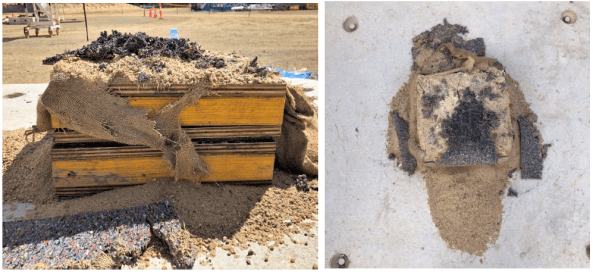
The support pads consisted of a concrete pad with a specified shim arrangement on top; the shims consisted of an anti-slip rubber mat, sandbag, and timber shims made from TRU Form and LVL plywood. Each segment had a specific support pad shim arrangement to suit the segment profile detailed in the Temporary Works 23 design package (TW23).
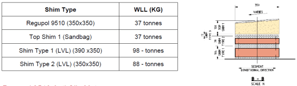
An example of the shim arrangement is shown below. The WLL table was produced as part of the post-incident analysis and was not available on-site prior to the incident.
Segment P5-1U was one of the larger segments cast to date and as a result, was to be utilised during the Straddle Carrier Crane Safe load test scheduled for Tuesday 26th September. The Straddle Carrier WLL was 110 tonnes. The Crane Safe certification test required a test load of 110% (121 tonnes).
On Saturday 21st September, the Precast Manager instructed the crane crew to place concrete pads next to the segment in preparation for the load test. Later the crew were instructed to load four concrete pads onto the Segment. Between 10:00 – 12:00 four concrete blocks, each weighing 2.2 tonnes, were placed by the crawler crane in predetermined locations on top of the segment to achieve the required weight for the Safe load test.
The following table shows how support pad B was overloaded by 28.4% prior to adding the concrete blocks and 40.3% after adding the blocks.

At approximately 12.30 a truck arrived from the main bridge site, returning a spreader beam. The truck driver was instructed by a rigger to park within the radius of the nearby crawler crane. The crane crew unloaded the spreader beam; the truck driver then proceeded to prepare his truck for departure.
I highlight the interface between concurrent activities on site which contributed to the severity of the incident.
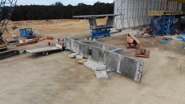
At approximately 12.55, almost 28 hours after placing the segment, the truck driver was standing at the back of his truck and heard a noise. Upon looking up, he saw the segment moving at which point he quickly moved further away from the back of the truck. The segment then fell over, landing on the cab of the truck and concrete pads.
The truck driver had just tightened his last truck ratchet strap and was about to get back into the cab of his truck.
The following picture shows the failed shim. The grey/black material is the Regupol mat.
The Precast Manager immediately attended the incident scene and, having determined no one was injured, secured the area and ceased all works in the precast yard, and made the required notifications.
Key findings:
• The WLL of the anti-slip rubber mat was not checked during design
The design had been used previously on another project in Sydney however the segments on that project had a maximum weight of 70 tonnes.
• There was no technical specification for the sandbag in the design
• The WLL of the anti-slip rubber mat was exceeded by 10.5 tonnes (28.4%) prior to the placement of the concrete blocks (8.8 tonnes) and by 14.9 tonnes (40%) when the additional 8.8 tonnes was added for the Straddle Carrier Safe load test
The issue of the inadequate design was exasperated by a site change to the load test procedure.
• The TW 23 design package was assessed as Low Risk, requiring no independent design certification. Had the risk been rated as “significant” (i.e. by way of Catastrophic consequence and Unlikely frequency, independent design certification would have been required.
• Support Pad inspection on P5-U identified there was not full contact between the various shim layers and the segment. Thus load transfer may not have been evenly distributed across the surface and may have resulted in potential point loading. This may have placed further stress on the anti-slip rubber mats
• The support pad design was not reviewed following initial issues observed with the sandbags during the placement of the segment P5-U
However it was discussed with the Engineers, Precast Manager and TWC.
• Support pad failure was not identified as a risk when planning the Safe load test, therefore no exclusion zone established around the segment.
Hence the truck was directed to park within the crawler crane radius for unloading. This was next to the stored segment.
Actions:
• Establish an exclusion zone around segment P5-U
• Design a temporary support system to secure Segment P5-U, before lifting and reseating on the new temporary support system.
The segment has been quarantined and cannot be used. It will now be crushed for disposal.
• Review Segment Storage Pad (TW23) design and design validation by an independent professional engineer
Works in progress.
• John Holland TEK Team shall conduct a project-wide Temporary Works Audit (3 days)
• Review the Design Management Plan to include the requirements of JH-MPR-DES-003 TEMPORARY WORKS DESIGN AND IMPLEMENTATION
• Review the Temporary Workers Register classifications and ensure design verification and validation is completed in accordance with JH-MPR-DES-003 TEMPORARY WORKS DESIGN AND IMPLEMENTATION
Review and audit of all TW activities and processes conducted by an independent JH team.
• Review [Activity Method Statemet] to include temporary pad installation and segment placement, detail all temporary works design requirements associated with the activity.
• Develop [Task Risk Assessment] specific to the task of pad layout, installation and placement of segments
• Inspection and Test Plan (ITP) check for pad configuration and shim configuration
• Project Wide toolbox discussing the importance of speaking up if you have an issue or concern
• Communicated Change Management requirements to the wider project team
▪ SQE Risk Management
▪ Design Change
▪ Resources (plant, people, equipment)
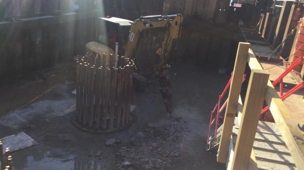
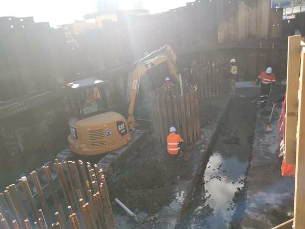
Pile Cropping
posted about how his project was using a mechanical pile cropper to remove the excess portion of the driven pre-cast piles. This method is suitable due to the high number of piles and small diameter of the pile head.
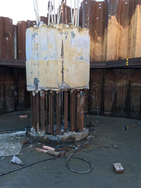
On my project, we have 21 bored piles which vary in diameter between 2.1m and 2.4m. The piles consist of a 16mm thick hollow casing is vibrated into the ground to an established depth. A drilling rig is then used to remove the spoil from within the casing and drill a prescribed depth into the rockhead. When the geotechnical engineer is happy reinforcement cages are secured in place and the piles are poured using a tremie method (to prevent concrete segregation and due to groundwater horizons). This method means that poor quality concrete rises to the top of the pile during the pour (due to laitance) so to compensate the piles are poured a couple of meters higher (‘the overpour’) which is removed as waste concrete. This exposes the reinforcement which is then tied into the pile cap. Due to the large diameter and low number of the piles and the requirement to minimise bending the pile reinforcement a mechanical pile cropping method isn’t feasible.
My project has been using an ‘innovative’ chemical expanding system called Recepieux to break off the overpour at a set level with the overpour lifted off by a crane using pre-installed lifting hooks. This minimises the amount of jack-hammering required pile head and saves a significant amount of time and money. Well at least that is the theory…
To find out more about Recepieux follow these links:
Of the 6 piles the system has been used on so far we have had a 50% success rate. Of the successful breaks, we have struggled to lift off the overpour with a crane so have also used jacks to assist with the removal. A new system on-site often has teething problems and the team have adapted their methods to improve the reliability of the installation, decrease rebar bonding and pre-cutting of the steel casing assist concrete cracking. For the 50% that failed (first 3 piles poured) two weeks of jack-hammering ensued adding delays, noise and dust emissions. The next piles we will be using the system on are marine piles so I’m hoping we have more success as there is limited space for jack-hammers.
Below are some pictures and videos from site:
Recepieux fixed to rebar cage prior to installation inside the casing
Jack-hammering overpour where recepieux was unsuccessful – increased environmental pollution from noise and dust.
Additional labour costs to remove waste and construct access platforms
Recepieux flasks failed to expand as expected
Expanding grout had not had the anticipated effect
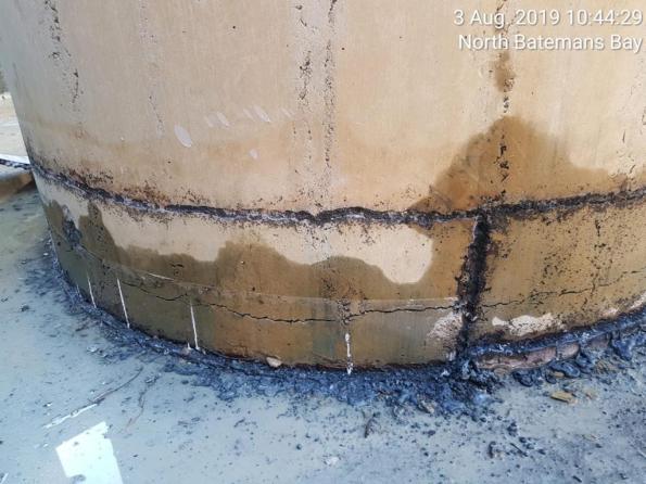
Improvements made to recepieux installation resulting in a crack around pile (note the dark black marks are from oxy-cutting the casing to remove it)
Hydraulic jacks were used to assist removal as the crane could not remove overpour due to the rebar bonding to the concrete
Early stages of jacking
Getting closer 60mm at a time…
Overpour removed
(the video makes it look a lot closer than it was…
a number of H&S issues were improved on)
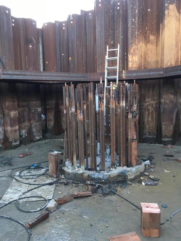
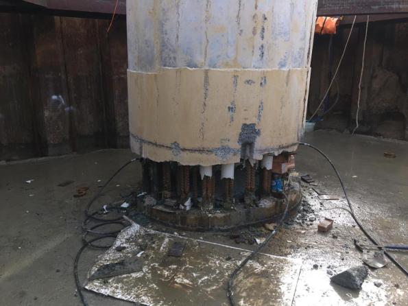
Rebar exposed after overpour removal. Head of pile cap cleaned up and levelled using manual methods
The following document shows the formulation of the above method by the TWC on site: BBB-VSL-DWG-TW-3054-A-
Temp PT
Tom, I’ll keep this one short just for you!
I’m currently writing a SWMS for the installation of 98t precast pile cap shells onto the marine piles. The idea is a RC precast shell is constructed on the foreshore and the steel working platform installed prior to the lift. Once in position, the gaps between the piles and the shell are grouted with underwater grout and the water removed to create a working area to remove the pile overpours and complete the RC pile cap. The working platform is then used to support the TW access platforms for the pier construction.
It seems quite a clever and well thought through. There are only a few challenges to the plan:
- Piling and pre-cast shell tolerances require a larger hole in the precast pile cap shell than the pile casing. This will let water in.
- In order to seal the gap between the pile casing and precast shell a seal is required to prevent environmental contamination of the river a seal is required. This will need to be positioned and removed (ideally without using divers due to cost). You can buy inflatable ring seals for this purpose but in true Blue Peter style we are making our own from plywood forms and rubber extrusion seals (think large car door seals). We have been doing lots of discussing and sketching of ideas in the office so I look forward to seeing if it will actually work.
- A method to lifting the precast shell and suspend it in the correct position is until permanently connected to the piles is required. This is what I want to blog about.
To lift the precast pile cap shell two lifting beams have been fabricated (each beam is made from twin 457 x 152 UBs joined together with additional stiffeners, bearing plates and lifting lugs). To suspend the shell at the correct position three hanging beams (same design as lifting beams) are used and will fix to the pile casing (2100mm diameter steel CHS 6mm thick). To counter the uplift forces a hold-down bracket and clamp system is proposed (but unworkable as we can’t source the required clamps) and are requesting a design change.
The shell lift will need to be conducted in two stages. The first using a 400t land-based crawler crane (with maxer) to position the shell closer to the river bank. The second stage will use a barge-based 400t crawler crane (with maxer) to pick up the shell and position it onto the piles. The problem is how do you stop the concrete being subjected to tensile stress?
The solution is temporary prestressing. The design includes 10 No. 40mm diameter prestress bars anchored into the shell wall below the lifting/hanging beams. A number of load cases have been examined which determines the lifting case is the most critical. To prevent the development of tensile stresses the bars were initially due to be stressed to 670kN to give a retained stress of 500kN after prestress losses (mostly due to lock-off). Further calculations indicate the concrete shell would fail if the bars were stressed to 670kN so the pencil has been sharpened and a new prestress limit of 470kN is proposed (300kN retained stress). This is still undergoing verification but as the pile cap shell base was poured last week and the walls are being poured tomorrow things could quickly change.
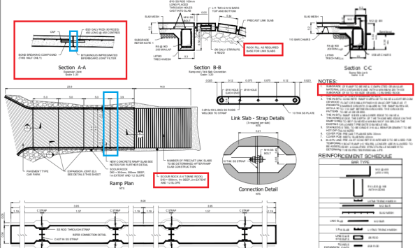
I thought this was an interesting use of temp PT by VSL who specialise in PT (as Freyssinet’s main competitor) so I hope you enjoyed the read. Below is the proposed construction sequence and precast pile cap shell drawings (temp PT highlighted in red boxes).
Planned construction sequence:
Stage 1 (not shown) – install sealing rings.
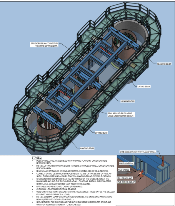
Stage 2 (above) – Lifting pile cap shell onto piles. Model shows lifting beams, hanging beams and temporary working platform.
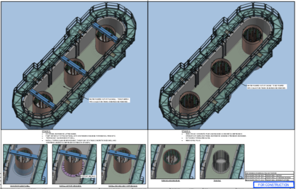
Stage 3 (above LHS) – Removal of lifting beams and sealing of gaps and removal of water.
Stage 4 (above RHS) – Second stage slab pour, removal of hanging beams and removal of pile overpour and excess casing.
Stage 5 (not shown) – Complete pile cap RC pour
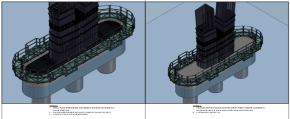
Stage 6 and 7 – Construction of bridge piers (additional working platform construction not shown).
Pile Cap Shell Drawings
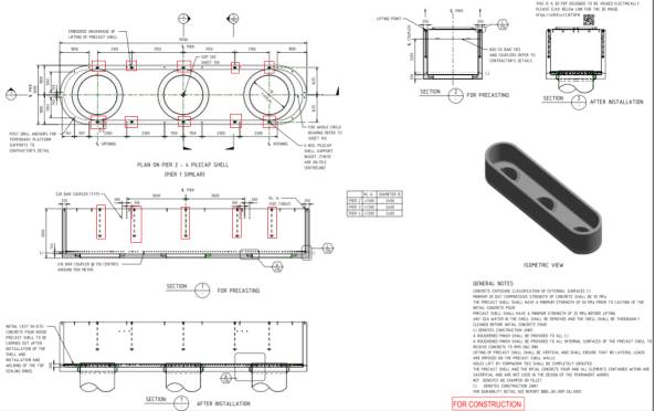
Pile cap shell drawing (above)
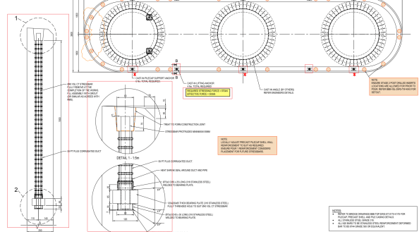
Temp PT drawings (above)
Revit Model
Tony Guy Partners (the permanent bridge designer) have added QR codes to their drawings with web links which allow anyone to download the revit model for that drawing from Autodesk myhub. No Autodesk software licenses are required and it allows 3d mark-ups, exploded views and sections/cuts to be viewed. These have been a real lifesaver for the engineers working on the rebar schedules/ITPs.
If you want to view the model you can download it from this weblink: Pile Cap Shell Revit Model
Practical Lessons from Cofferdams
Note: Pictures are included at the end of this post.
Background
As part of the bridge sub-structure package, my team has been responsible for the construction of two cofferdams on the foreshores of the Clyde River to construct the pile caps. I was responsible for the planning of the cofferdam works. Unfortunately, I was off-site when some of the works were executed but have been involved in resolving a number of the issues outlined in this blog.
The northern foreshore cofferdam is located at bridge pier 1 and the southern cofferdam at bridge pier 5. The Clyde River is tidal at Batemans Bay with tides typically varying between +0.900m AHD (Australian Height Datum) to -0.500m AHD. The Geotechnical Design Report concludes that the groundwater is assumed to be hydraulically connected to the Clyde River.
The cofferdams are slightly irregular in shape (trapezoidal) due to a HV cable running within 300mm of the cofferdam wall at Pier 5. The same design was adopted for both cofferdams to reduce design costs and the works planned sequentially to reduce fabrication costs by re-using one set of waler beams. Later a decision was made to accelerate the construction programme which required a second set of walers and concurrent construction adopted.
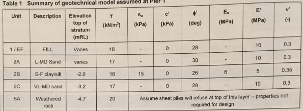
Ground investigation boreholes indicated a varying rock profile with bedrock occurring at approximately RL -5.000m AHD at Pier 1 but in excess of RL -30.00m AHD at Pier 5. The geotechnical design models for the cofferdams at Pier 1 and 5 are shown in the tables below. It was anticipated that cut-off could be achieved at Pier 1 but not at Pier 5 due to the rock-head depth.

Pier 1 Cofferdam
The northern cofferdam is located within the tidal zone. At low-tide, all sheet piles are above the waterline but at high-tide the majority of the cofferdam sheet piles are within the river.
The cofferdam was constructed at Pier 1 in two stages. The first stage was to drive the sheet piles on 3 sides of the cofferdam to create cantilevered retaining walls for the construction of a TW platform for a piling rig. The rig installed 3 No. permanent bridge piles (1.8m diameter bored piles) before the cofferdam was closed. When the cofferdam was complete all sheet piles hammer-driven 200-400mm into the rock-head.
GU18N piles were procured and cut down on-site to reduce the number of piles required. The minimum design embedment was RL -5.000m AHD. The external ground level on the land-side was is RL +1.700m AHD with a final excavation depth of RL -1.200m AHD before 150mm of drainage rock and a 50mm blinding layer was placed.
Delta-13 corner connectors were used to increase water-tightness however the connector at the final corner could not be installed correctly due to differences between the design and as-built alignments.
Pier 5 Cofferdam
Due to program sequencing and existing access for the piling rig, the 3 No. permanent bridge piles were installed prior to the cofferdam construction.
The Pier 5 cofferdam is located approximately 15m from the edge of the river bank. 12.0m SPU-IIIw piles were driven under vibration to a minimum toe embedment of RL -9.600m AHD. The surrounding ground level is a TW platform at RL +2.000m AHD and a final excavation depth of RL -1.850m AHD was achieved (based on the on-site Geotechnical Engineer’s direction) before 300mm of drainage rock and a 50mm blinding layer was placed.
Again delta-13 corner connectors were used to increase water-tightness however the final connector could not be installed variation from the design and as-built alignments.
Problems:
- Budget. The cost of the cofferdams was overlooked during the tender, therefore, the cofferdam works had no budget. All decisions have been made on this basis with no appetite for additional expenditure to mitigate potential risks that may not materialise. Observation: Remember to include the cost of TW in tender submissions.
- Confined space requirements. When is a cofferdam a confined space? It seems everyone has an opinion and no two are the same! On the southern foreshore there are mangrove swamps which creates the potential for the soil to contain pockets of hydrogen sulfide gas (H2S) due to the decomposition of the organic material. High concentrations of H2S gas have been found at other project sites on the south of the river. A lot of my time planning the execution of the cofferdams was spent managing the potential confined space risks that could occur in the cofferdam due to H2S gas and plant or welding fumes. The risks to workers were reduced by providing ventilation fans to circulate air and using gas detectors to monitor the atmospheric (oxygen, carbon dioxide, hydrogen sulfide and explosive gas levels) to ensure levels remain within acceptable limits. As part of this process every shift I conduct a confined space assessment to determine if the cofferdams should be classified as a confined space. Observation: The risk of contaminated ground was covered in the teaching prior to Ex COFFERDAM but I don’t recall discussing confined space risks. Would this risk be worth highlighting to future PET courses?
- Lack of knowledge. There is a lack of knowledge about cofferdams amongst the site engineers. I found that I had more knowledge than most based on Ex COFFERDAM. One Senior Project Engineer initially designed the cofferdam (before an external geotechnical consultant was employed to verify the design). He has admitted that it was the first time he had designed one and would do things differently if he was to design another cofferdam. A John Holland supervisor has constructed cofferdams previously on other projects. Observation: You might actually know more than you think after Phase 1.
- Personalities. I have found the personalities of the site supervisors key in the standard of works they achieve. One supervisor is optimistic, under-resourced and over promises – consequently, he routinely fails to deliver. Another supervisor is well-organised and has invested time in building his team – they routinely deliver works to a high standard. Observation: It has been interesting to observe the same design delivered by the different teams and observe how their work ethos has affected the problems faced on site.
- Pile procurement. To reduce the cofferdam costs surplus/second-hand sheet piles and connectors were purchased from other construction sites. Essentially you get what you pay for – the poor quality second hand piles have caused a number of issues on site (increased labour costs, slower installation rates and clutch leaks). Observation: Trying to save money upfront has cost significantly more in the long run.
- Clutch Leaks. To save money, no clutch sealant was used prior to driving the sheet piles. The view from the optimistic supervisor was that the cofferdams would be fairly watertight and any leaks could be sealed post-excavation via calking rope or welding. At Pier 5 the wall leaks have been relatively minor except for at the corner where the delta-13 connector could not be installed. This resulted in a surface sinkhole as the groundwater caused fines to migrate into the cofferdam. This was sealed by blocking the gap and using stabilised sand to prevent further fines migration. At Pier 1, every clutch leaks…badly. Due to other work priorities, and needing to work at low tide slow progress is being made on welding the clutches. Observation: This is a big issue for permanent work construction as the groundwater will contaminate the rebar and prevent concreting works. Options for sealing a cofferdam after sheet pile installation are very limited – it is advisable to use clutch sealant before driving the piles as the other methods as it is too late when you start excavating.
- Boiling/Piping? At Pier 1 due to the rock-head and reduced toe embedment, there appear to be issues with a high hydraulic gradient boiling at the base of the excavation in the middle of the river sidewall even at low tide. I’m not sure if this would be classified as boiling/piping but you can see for yourself in the video below. This increases the groundwater flow into the cofferdam with 100mm routinely made overnight and up to 500mm over a weekend. In contrast, the increased embedment depth at Pier 5 appears to have minimised the issues with groundwater penetration due to the increased hydraulic flow path around the sheet pile and the increased soil plug weight inside the cofferdam. Of note, the drawings state ‘water tightness of temporary structure not designed. If waterproofing is required, to be designed and documented by others.’ Observation: I have not found any assessment of the hydraulic gradient or flow net for the cofferdam. This appears to have been largely ignored during the design stage. I have measured the recharge rate of the Pier 1 cofferdam but have been unable to assess this further due to other workloads.
- Groundwater. The lack of geotechnical knowledge and understanding of groundwater is worrying. A spear dewatering system was installed at Pier 5 but there was significant disagreement of when it should be turned on and off. The system was removed following the blinding layer installation as the system was extracting 0.5l/sec which the SPE felt could be managed via sumps. This is achievable during working hours however site environmental restrictions prevent dewatering out of hours which has resulted in a flooded cofferdam in the mornings and at weekends following high tides. The ability of the spear system to depress the groundwater level below that of the sump is not understood nor is the importance of running the dewatering system over a protracted timeframe to depress the groundwater levels. Interestingly I have just been instructed to organise the installation of a spear dewatering system in the Pier 1 cofferdam to reduce the water entering the cofferdam. I believe this is the only option we have to control water ingress below the blinding layer as the clutches are not sealed. Observation: The rush to demobilise ‘unnecessary’ dewatering equipment is causing challenges with the permanent works (reinforcement and concreting works) which need to be kept out of the groundwater.
- Alignment. There were significant issues with maintaining the design alignment when driving the sheets as no driving frame was used (sheets were driven individually). As fixed walers were fabricated the 300mm+ variation was significantly more than could be accounted for with metal packing shims. A Temporary Works Modification Request was approved which replaced the fixed waler support brackets and metal shims with restraint chains and hardwood packing. At pier 1 the location of HV cables within 300mm of the wall required non-destructive testing to expose the cables so the asset owner could observe the cables as the sheets were driven. This required formal notifications, additional Safe Working Method Statements and made installing and aligning the wall more challenging due to the open trench. Observation: Adjustable proprietary strut/prop systems can be adjusted more easily to compensate for installation inaccuracy. If using fabricated (fixed) props I recommend assembling the walers first in situ and using them as a driving frame to minimise alignment variations. Proprietary waler restraint chains were far easier to install than the fixed bracket design.
- Quality Issues. The works were due to be self-performed by John Holland (JH) employed labour to reduce costs. A JH crew started the sheet pile installation at both cofferdams but later handed it over to a sub-contractor (the Temporary Boat Ramp failure [see previous blog] disrupted the permanent piling contractor’s works so they were employed on day rates to perform additional works to minimise demobilisation costs). The cofferdams have subsequently been handed between JH crews. With the works starting behind programme the focus has been on time at the expense of quality. Pier 1 sits on the project critical path. The blinding pour was rushed and started too late in the afternoon to be completed within the site working hours. This resulting in inconsistent blinding levels above the RL and critical trench reinforcement (to support the pier formwork) being installed in the wrong position (horizontally and vertically). Critical sections of the blinding including the trench reinforcement have been ripped out and replaced loosing over 4 days of productivity at Pier 1. Observations: The lack of crew ownership combined with a desire to recover the programme and a vague ITP has resulted in the delivery of low quality work. This is most noticeable at Pier 1. The Pier 1 blinding pour should have been delayed. The engineer managing the blinding pour was pressured into making mistakes.
- Wall Monitoring. Part of the designer’s requirement was to monitor wall movement at 16 locations around the cofferdam (2 positions on each wall at waler height and 2 positions on each wall 0.5m above the base excavation level). Set deflection limits were agreed including 80% trigger levels to increase monitoring requirements. This was a great idea in principle but was practically impossible to achieve on-site due to physical site and line of sight constraints. This was discussed with the designer and a practical proposal developed on site. The wall monitoring was to be conducted daily until the wall movements stabilised. The monitoring identified that the Pier 1 land-side wall one wall moved 17mm (greater than the 80% threshold limit) over a weekend. This triggered significant consultation with the geotechnical engineers and structural designers to determine a solution. The wall movement was attributed to a surcharge load from an excavator (which was permitted in the design). As the deflection remained less than those permitted in the cantilevered state new deflection thresholds were agreed with the designers. The wall movements have no re-stabilised and are monitored bi-weekly by the site surveyor. Observation: The set wall monitoring procedure developed with the site surveyor was essential to detect the wall movement. Simple solutions developed in an office may not be practical on-site. The designers were receptive to adjusting the monitoring plan based on-site practicalities.
Any guidance or ideas of how to seal the cofferdam clutch leaks would be very welcome!
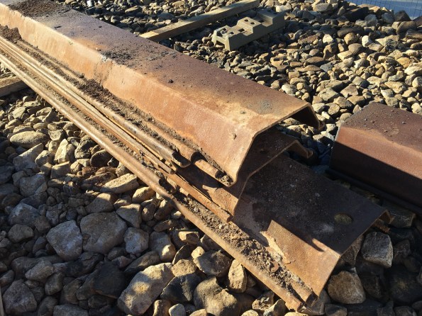
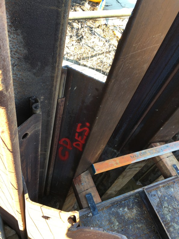
The state some of the second-hand piles arrived in…
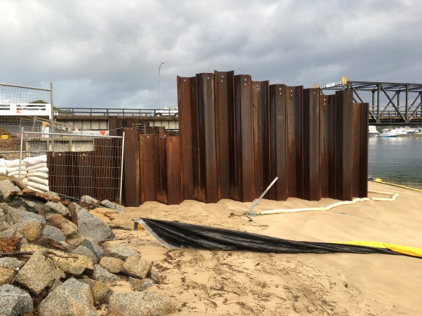
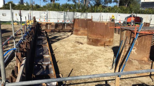
Pier 1 cofferdam as cantilevered retaining walls for the piling platform
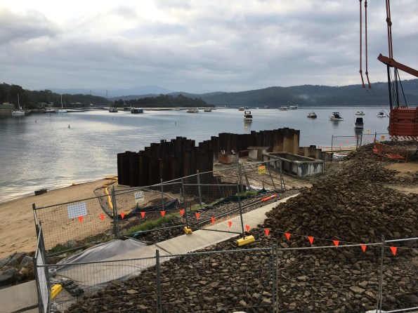
Pier 1 cofferdam showing proximity to river at low tide. Piles on LHS are shorter to reduce the number of piles and prevent tides from entering cofferdam around the side during construction.
Pier 5 cofferdam at stage 1 dig (prior to waler install). The foreground shows the dewatering spear system and header main.
Pier 5 cofferdam waler installation.
Pier 1 delta-13 connector not closing on sheet pile clutch due to misalignment
The lack of delta-13 connector at the Pier 5 resulted in visible groundwater flow
The groundwater flow washed fines through the gap resulting in a sinkhole outside of the cofferdam.
Installation of walers at Pier 1 cofferdam (level appears lower due to removed piling rig platform removal and reduced toe depth.

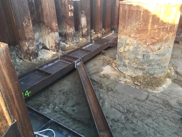
The waler restraint chains were used to solve the issue of a lack of sheet pile above the waler at Pier 5. The chains were easier to install than the fixed brackets. Note the timber packing that was initially due to be 1-10mm steel plate.

Blinding layer complete at Pier 5
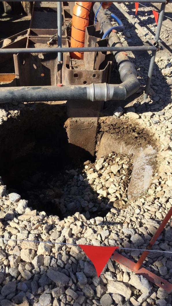
Meanwhile high hydraulic gradient at Pier 1. Possible piping/boiling? The sand is being forced into the cofferdam from the river bank/beach outside the cofferdam.
Pier 1 water penetration through the clutches due to tide.

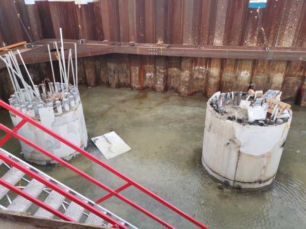
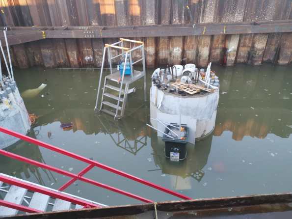
Flooding at Pier 5 due to groundwater. Usually <50mm.
Flooding at Pier 1 cofferdam. My usual morning view of 80 – 100mm above blinding layer.
Pier 1 following a high tide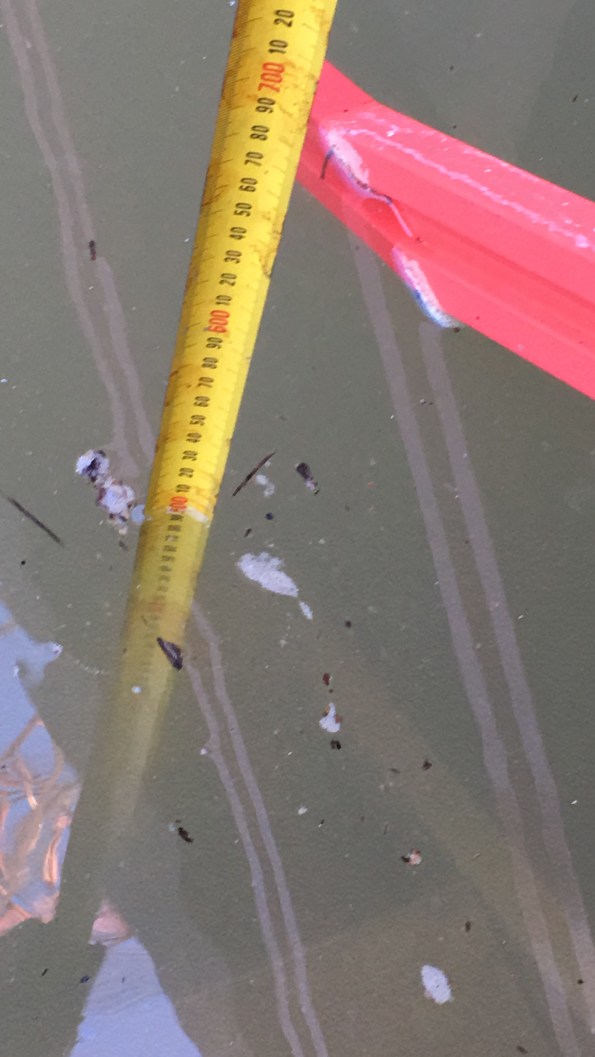
Pier 1 record water level of 500mm above blinding following a weekend with high tides.
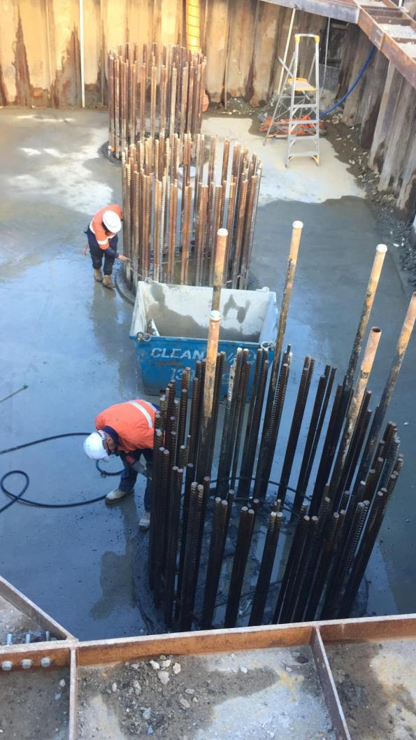
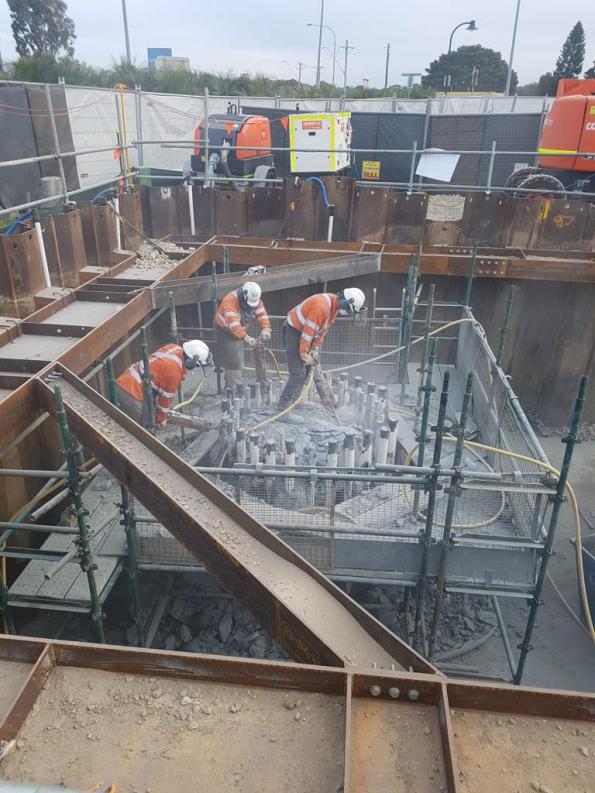
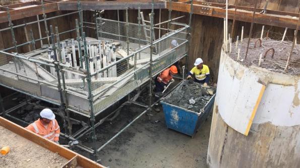
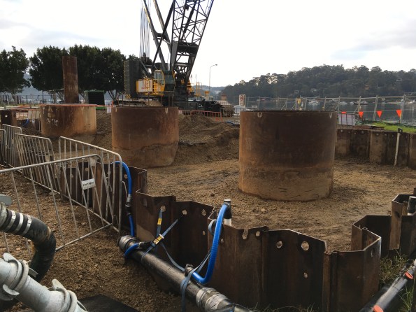
Pier 5 pile overpour break back complete. Cleaning rebar for insitu pile cap. Groundwater managed by sump pump (back right corner).

Current works at Pier 5. In situ steel fixing.
Current works at Pier 1. Breaking out blinding and reinforcement.
New blinding in the excavated trench was laid at Pier 1 today.
What is a Soft Start?
A few weeks ago we had two notifiable incidents occur within 24 hours. Fortunately, there were no injuries but both were classed as the most severe category (1P) under the John Holland reporting system as they had the potential for workers or the public to be killed. Details about the two incidents are included at the bottom of the blog but for the timebeing, I want to focus on the procedure to restart works.
What interested me most about the incidents was the Project Director’s response. After conducting John Holland’s reporting procedure and informing the Client of the incidents he closed the site. The next working day all directly employed staff attended a meeting where the incidents were discussed in detail. The bottom line was that safety is always the priority and that these incidents were a ‘free pass’ as no-one was injured but we needed to to do better going forward. He identified 5 key areas of concern:
- Services
- People and Plant Interaction
- Lifting operations
- Temporary Works
- Pubic Interaction and Traffic
Following the meeting all construction managers, engineers and supervisors were tasked with reviewing their procedures, Safe Working Method Statements, Task Risk Assessments and work permits for their respective areas. The workers arrived mid-morning and were involved in the process. The afternoon consisted of site health and safety inspections to identify areas for improvement. This allowed improvements to be made to the existing procedures, method statements and constructions site set-up. A feedback session was conducted late afternoon for the directly employed staff. No project productive works were completed that day.
The next working day a ‘soft-start’ was conducted which was a gradual return to works with the identified changes implemented under closer supervision from the supervisors and engineers. For areas requiring additional time to review their procedures and documentation, the Project Director supported the delaying of the ‘soft-start’ in their area for as long as was required.
What impressed me about the way this was handled?
- The Project Director was clear where his priorities lay and drove the process.
- It generated increased involvement and attention from the construction managers and senior engineers that I hadn’t experienced previously on site.
- The time to pause and review was critical.
- Input and empowerment of the workers was essential.
- The Project Director was willing to bear the cost of a non-productive day and liaise with fixed price contractors as required to ensure their buy-in.
- A re-focus on the basics. John Holland has a set of Global Mandatory Requirements (GMRs) that are used to manage key construction risks which are used when planning activities. These headings formed the basis of the review. On site we have a handy booklet but the GMR sub-headings can be viewed here.
I’m interested to hear if anyone else has experienced anything similar on site. If so how was it handled and what did you learn from it?
Incident #1:
The first incident was a dropped load from a gantry crane at the pre-cast yard. A worker was using a gantry crane to turn over a pre-cast mould bulkhead to weld plates on both sides. There were a number of factors that caused the incident in a ‘swiss cheese’ scenario:
- The worker operating the gantry crane is a dogman (rigger or slinger in UK/military terminology) but had not been used much in this role previously on site.
- The worker had not operated the gantry crane before but the supervisor thought he had. (Following the incident it has not been possible to determine if the individual completed the on-site training from the gantry crane supplier as no record of the training was maintained).
- The worker was not aware of the designed lifting points on the bulkhead.
- An engineer was asked about the weight of the lift. The engineer remembered lifting a bulkhead previously so stated the weight he remembered. No plans were checked and he estimated the weight incorrectly.
- The worker decided to use soft-slings to lift the load. He was aware of the potential for the metal edges to cut into the slings so used rubber to pack the metal edges against the slings.
- As the load was picked up the rubber packing moved.
- The soft-slings were cut/snapped on one side of the load resulting in a dropped load onto the foundation slab.
Following the incident works were halted, the load was made safe and the incident scene preserved. Senior management were informed and external bodies notified. The senior management team used a technique called 5 Whys? (similar to the combat estimate and asking ‘so what’) to get to the root causes of the incident. A number of areas were identified that could have prevented the incident from occurring. Examples include:
- A bespoke and accredited gantry crane operators course.
- Identifying designated gantry crane operators and alternative operators.
- All precast lifts are identified at the morning pre-start and discussed with the team.
- Two engineers are required to check the drawings and calculate the weight of each lift independently. Their assessments are compared prior to conducting the lift.
- The use of soft slings is now restricted at the precast yard with a permit system adopted.
- More emphasis has been placed on ensuring the correct mix of qualifications and site experience (SQEP) across the work crews.
- Giving nominated personnel responsibility for tasks such as maintaining designated work zone signage.
These have now been incorporated as new processes or procedures at the precast yard with the Safe Work Method Statements and Task Risk Assessments updated accordingly.
Incident #2:
The second incident related to an excavator which hit an elevated LV cable when tracking from one working area to another and pulled it down to ground level. This was classified as a 1P event as the pylon also had a HV cable which was not disturbed. Again there were a number of factors that contributed to the incident:
- In preparation for the weekend site closedown, the excavator operator was instructed to conduct environmental controls in a different area of the site.
- The excavator driver was guided by a pedestrian spotter under the power cable to access the other area of the site and completed the environmental controls.
- The excavator operator returned to their original working area but was not guided under the power cables.
- The operator was aware of the power cables but lost sight of them as he was passing under the cables resulting in contact with the LV cable.
A similar incident review process was carried out and the following root causes identified:
- A change in planned activities (over here they call it Change Management*). This is considered to be a contributing factor in most site incidents.
- No ‘goal-posts’ or overhead power lines signs were displayed. The signs would have had little effect as the operator knew about the power lines but the ‘goal-posts’ might have given warning that the excavator’s arm was too high.
- There was no requirement to track the excavator across the top of the embankment. Traffic barriers have now been installed to prevent access.
- The operator failed to adhere to the project spotter procedures when operating near power lines.
*This is different from the use of the term on Project ANEMOI where it refers to the deliberate/planned change of the design following a formal process.
It always comes out in the wash…
Introduction
Gareth – it sounds like we could have done with the approach you describe in your blog post about 4 weeks ago… A little more attention to detail and closer supervision might have been of benefit!
The past few days have seen unsettled weather across eastern Australia. There has been snow in the mountains and even in the sunshine state (Queensland) to the north. The area I am in has survived largely unscathed however we have had high winds (gusting up to 130 kph stopping crane operations) and over 70mm of rainfall in one night (for perspective, site drainage is sized against a 37mm event).
Today was due to be the completion and opening of a new public temporary boat ramp which would allow us to close the existing boat ramp and start piling works on the temporary jetty. The jetty is required to transfer precast bridge elements from the shore onto barges in the river. At least that was the plan until 0705 this morning…
Background
Due to a number of delays, the senior site management has decided to conduct concurrent works to save costs and recover the programme. This has required a number of activities to be brought forward onto the critical path. To gain momentum on these activities some engineering ‘best guess’ has been applied in order to complete designs and gain environmental approvals. The temporary boat ramp is one example of this and there has been a big push to construct the temporary boat ramp as quickly as possible.
John Holland initially struggled to attract enough experienced site and project engineers so have backfilled with a number of engineers from their graduate programme. Sadly due to the lack of experienced engineers in the office and concurrent works, a lot is being asked of the junior engineers who are getting limited supervision from the experienced engineers.
To meet the required boat ramp construction timeline the decision was made to use the concreting contractor working at the precast yard. For two months they have been producing pre-cast boat ramp planks alongside the in-situ concrete foundation at the precast yard. The past two weeks have seen the workers move across to the boat ramp site to complete the in-situ concrete pours and install the pre-cast planks. The construction of the boat ramp has been nothing but challenging and from the sidelines, it has seemed like everything was ‘going off half-cocked’ resulting in poor quality finishes produced by the subcontractor (but that’s another issue). All the time this has rested on the shoulders of one of the graduate engineers.
Temp Boat Ramp Drawing. Red boxes highlight the expansion joint detail and subgrade and rock armor notes. Blue boxes highlight the expansion joint.
So what happened?
This morning at the pre-start meeting (workers-management meeting) everyone was asked to check their areas for any issues. Shortly after the workers set off for the boat ramp the telephone calls started…
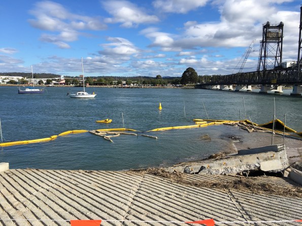
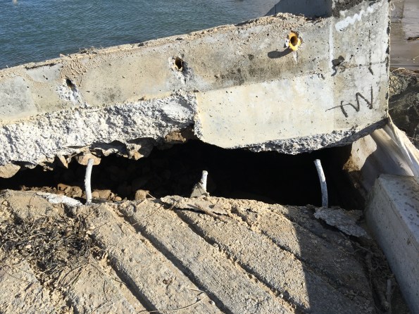
What follows are a series of photographs I took this afternoon at low-tide:
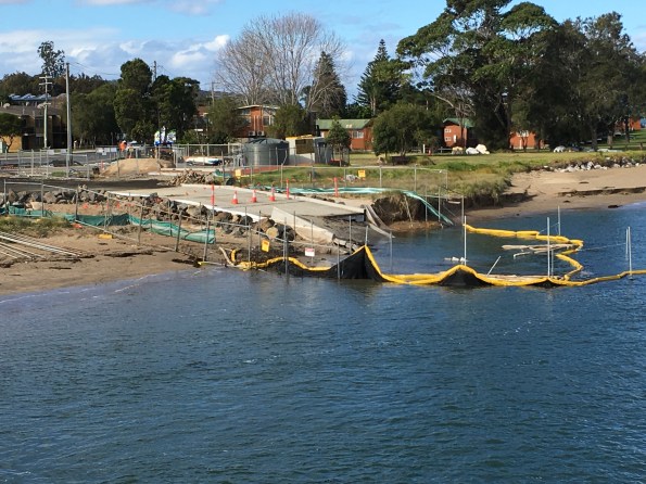
View from the existing bridge. The yellow and white floating items are silt and hydrocarbon booms which are part of the site environmental controls.
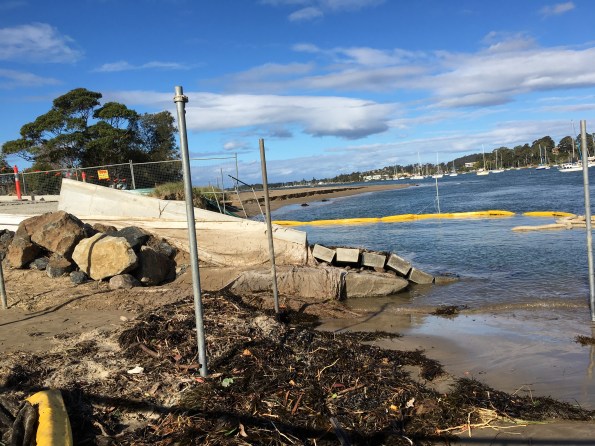
Side view from the bridge side. Note the rock armour on the left of the picture.
View standing on the ramp. Note the raised slab and seaweed position.
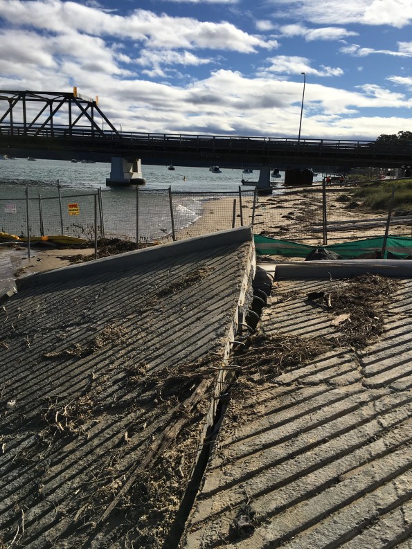
View back towards the bridge along the expansion joint. Note the curved dowels.
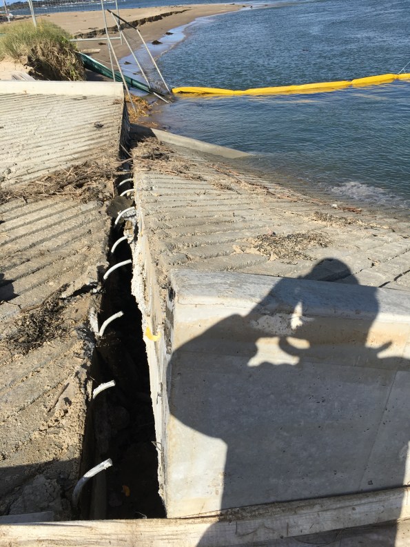
View along the expansion joint facing away from the bridge. Note the tilt and shift in the slab on the right of the picture.
Close up of lifted slab showing dowel sleeves and bent dowels. You can also see elements of subgrade stuck to the bottom concrete layer.
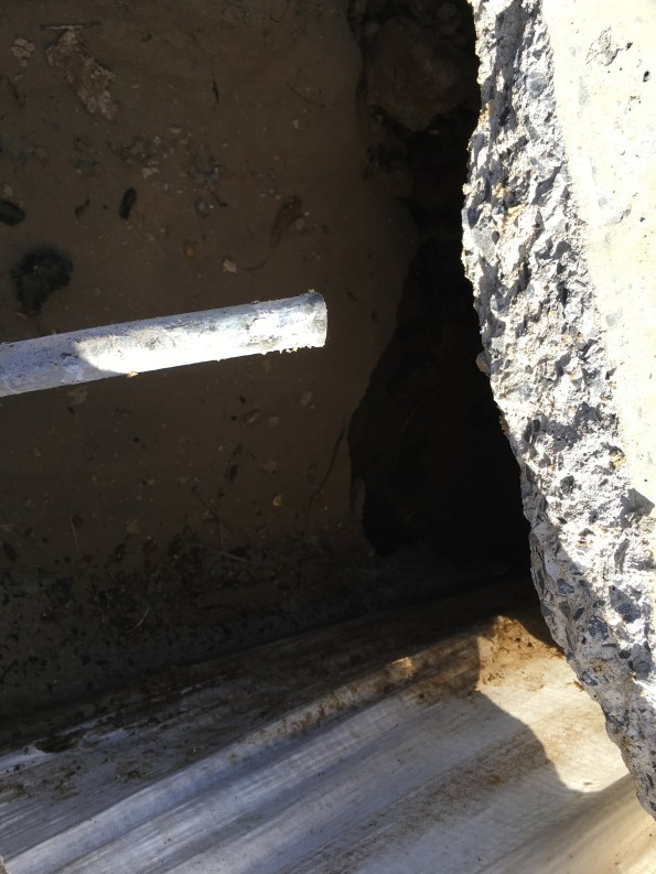
View between the slabs at the expansion joint. No subgrade is visible.
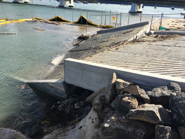
Side view facing back towards the bridge. The edge of the slab is 650mm thick so the slab has dropped at least 650mm at this side.
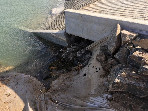
Focusing on the surrounding material. Note the geofabric, washed out material and missing rock armour. Apparently the workers tested the depth here with a 6′ scaffold pole which disappeared below the water surface at high-tide.
Analysis
It seems a number of errors and unfortunate circumstances have combined (swiss-cheese effect) causing a GEO failure. This resulted in structural failure of the expansion joint and serviceability requirements.
Today I was told the project looked at a number of locations to build the temporary boat ramp. The site near the bridge was chosen for speed and convenience despite recommendations not to build there. The sandbanks there are described as ‘highly-mobile sands’ and locals have known them to move frequently move position 10 – 15m. The site is also close to the existing bridge piers as you can see from the photographs. The combination of the piers in the river channel and construction of the boat ramp out into the river will have changed the river flow and velocity at the boat ramp location. This is likely to have increased the localised scour effects.
Typically the mean high tide level is 1.4m above the Australian Height Datum (AHD). Last night there was a high tide surge to 1.9m AHD (remember the seaweed in the photograph above) with water above the expansion joint. The effect of the surge (linked to the recent bad weather) was to undermine the boat ramp slab and scour away the foundations. Greater scour was experienced on one side of the ramp (seaward side) resulting in the slab tilt and shifting. The damage to the expansion joint was caused by the self-weight of the slab.
The drawings show a minimum 200mm subgrade of 50 – 150mm gravel or crushed rock. They also show the scour rock armour was to be 500mm deep and extend 1000mm from the ramp up to the end of the in situ concrete works. The rock armour was to continue around the precast planks in a larger size rock, 1000mm deep and 2000mm out from the precast planks. The rock armour was incomplete (due to be finished this morning) but already questions are being asked about the design and if it had been constructed correctly.
The bad news (from John Holland’s perspective) is that damage to works from tidal events are not insured (are John Holland’s risk) and the site is in the center of town so is bad PR. The good news is that no-one was hurt and the ramp had not been opened for public use.
Conclusion
It is still too early to determine exactly where the fault lies and if closer supervision of the junior engineers would have given a different result. The question is now is what’s ‘Plan G’? Was it an out-of-design event? Should we reinstate or rebuild elsewhere? DO we need to change the design to include sheet pile scour protection? I’m sure it will all come out in the wash (pun intended).
The impact will be significant reworks to remove and reinstate/construct (additional cost). There will also be delays to other project work packages as the existing public boat ramp cannot be closed. This will cause delay and disruption to the piling sub-contractor who will soon start to accrue daily standby charges. The figures make the eyes water! So a quick resolution is in everyone’s interest.
When things don’t go to plan… engineer your way out of trouble!
Over the last few weeks we have experienced a number of issues on site. For those who missed my first post, I am working on a bridge replacement project in Australia. My current job is working with the team to establish the precast yard for segment production. This post covers the main problems encountered so far and how we are engineering our way out of trouble…
- Design. The precast yard is essentially temporary works on a large scale. To maximise profit, the contractor spent limited time and money as possible on the consultant design. The result was independent design teams working on the earthworks, drainage, structural design and environmental plans. This approach could have worked however, no attempt was made to overlay and combine the designs. Needless to say there have been a number of oversights which have only been identified on site during construction. This issue has been compounded by a lack of access to CAD drawing files on site (and project level) and a lack of setting out information on the drawings. This has resulted in issues with the earthworks and drainage across site.
Lesson Identified: saving cost on design = additional cost in execution.
- Earthworks. A GPS grader was chosen to perform the majority of the earthworks due to ground conditions and speed, resulting in cost savings but has not proven to be the case. The grader was used to cut/determine the majority of levels on site. Although the technology is pretty accurate (verified by an on-site surveyor), the machine is only as good as earthwork model provided. Due to design constraints, the model was oversimplified and contained a number of errors. The result has been a lot of repeated work and significant overspend on earthworks. We are now using a surveyor to set out and confirm the remaining earthwork levels which is an additional cost.
Lessons Identified: (1) Technology is great when resourced correctly. (2) Always check levels with a surveyor.
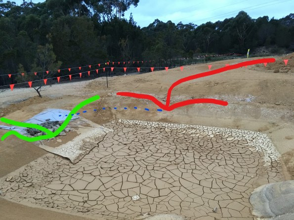
- Drainage (1). As alluded to earlier, the precast yard design has not been completely coherent. An example of this is the drainage ditch along the eastern boundary of the site. The ditch is shown in different locations on the stormwater and environmental plans (without setting out data) and is omitted completely from the site GA dwg. The ditch was initially constructed as shown on the environmental plan (alignment marked red in picture below) but was later identified during an as-built survey as being upto 10m into the segment storage area. This effectively halved the precast yard segment storage capacity and was considered unworkable. The solution was to move the ditch onto the site boundary (alignment marked in green) and spend even more money on earthworks!

For those with a keen eye, the embankment near the trees is well in excess of the approved design batter (45 degrees). I anticipated this and highlighted my concerns to the Superintendent and Precast PM prior to moving the ditch. The PM (a chartered Australian Civil Engineer) shared my concerns but it was decided to proceed. If required Superintendent agreed to stabilise (or potentially shotcrete) the slope later if necessary but nothing will be done initially to save money. I’m interested to see how the slope copes during the next period of heavy rain.
Lessons Identified: (1) If it doesn’t feel right trust your instincts. (2) As-built surveys can help identify issues early before they become a big problem (or nightmare to fix later).
- Drainage (2). During the early earthwork stages, one Supervisor decided to go a little ‘off plan’ and decided to connect a sedimentation pond at the northeastern corner of the site with the eastern ditch (shown above). This would remove the need for the sedimentation pond and allow free drainage around the site to a larger off-site sedimentation pond. Although a good idea in principle, after some extensive earthworks to connect the two features, it was realised that the Supervisor had failed to check the required levels. The picture below shows the eastern ditch highlighted in red and the north ‘overflow’ channel in green. The overflow outlet level is approximately 500mm lower than the eastern drainage ditch outlet. To work as the Supervisor intended the entire eastern ditch would need to be dug lower. Due to the earthworks overspend and slope stability issues this won’t happen.
Lesson Identified: Don’t cuff it, double check it.
- Piling. Due to the weight of the segments, deep foundations are required for the segment mould casting area. The solution was 52 No. 350mm square precast piles with predicted toe depths varying between 6.5m and 13.0m. Having only seen videos of piling I was excited to see live piling in action so made sure I had a good view for the first drive. The left-hand picture was taken after the first two piles had refused early at approximately 6m and 4m above the intended toe depth. The piling team started ‘sucking teeth’ over the more difficult than expected driving conditions which started a mild panic in the project team as the contract cost of pile ‘break-back’ per meter was going to cost a fortune. As briefed during the Retaining Soils module the piling crew left the piles to settle for over 24 hours and attempted to re-drive with an increased hammer weight. The right-hand picture shows a photograph of the piles at the end of driving. The good news was the first two piles were driven further (up to 3m); the bad news was that a number of piles were significantly proud. After searching for ‘experienced-wisdom’ and seeking advice from the piling sub-contractor, a method was devised to cut-off the excessively proud piles to reduce the amount of ‘break-back’ required. Pile Driving Analyser (PDA) tests were conducted on 5 piles which indicate the piles have an ultimate geotechnical capacity in excess of that required.


Lessons identified: (1) Don’t panic too soon. (2) The amount a pile can still be driven following an initial refusal is surprising.
- Reinforced Concrete Foundation Pour. This week we started the foundation pours. The first pour of 167m3 went relatively smoothly however the second 310m3 pour was slightly more dramatic. With pressure on to complete the pour as planned so the concreters could fly home for Easter and the steel erection team could start straight after Easter a big push was required. We initially made good progress and placed 200m3 before the sub-contractor’s concrete boom pump malfunctioned. For safety reasons, the Superintendent immediately prevented further use of the boom pump and instructed for the remaining section of the pour to be completed from the back of the cement mixers. There was no standby boom pump on site and as Batemans Bay is a small coastal town so there was no hope of getting a replacement at short notice. Due to site constraints, the remaining 100m3 in the next pour section wasn’t accessible by cement mixer so the rest of the pour had to be postponed. This initiated a chain reaction of phone calls between the batching plant, boom pump hire company, concreters and sub-contractors to rearrange for the next day. The biggest immediate problem was the 10m3 of concrete already on site that would be in excess of the completed section. We rapidly made plans to use some of the concrete as blinding for subsequent foundation pours however over 7m3 of concrete was wasted as alternative pour locations were not ready.
Lesson Identified: Always prepare an alternative pour location for excess concrete disposal.
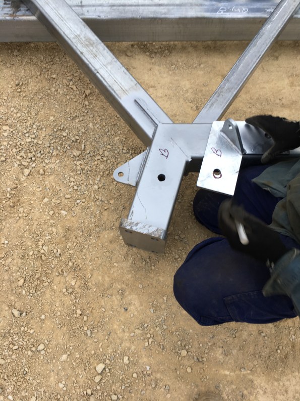
- Steel bracket fabrication. We have also been having issues with the steel frame provided by the fabricator. Their deliveries have been fairly hit and miss and not in a logical sequence to facilitate erection from one end of the structure. With the steel erectors on site this week we identified that all the plates supplied have incorrect bolt holes with each plate requiring a different remedy (picture below illustrates where the bolt hole should be). Due to the Easter and ANZAC Day public holidays, it would take two weeks to get the plates fabricated correctly. With hefty liquidated damages (LDs) for any components not on site before 26 Apr, the Superintendent brokered a deal between the steel fabricator and our steel erectors to adapt the plates on site and keep the steel erection on track. The steel erectors have conducted ground level on-site pre-fabrication this week as we are still awaiting delivery of key bracing components before the structure can be erected. With one delivery expected tomorrow (26 Apr) it will be interesting to see which items are on site before the cutoff and how the LDs work out. The good news is tomorrow I have to account for all the steel held on site – and I thought weapon serial checks were on hold for the next 18 months…
Lesson Identified: It’s the little things that stop the big things from happening…
Scale of Temp Works
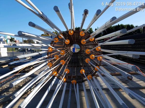
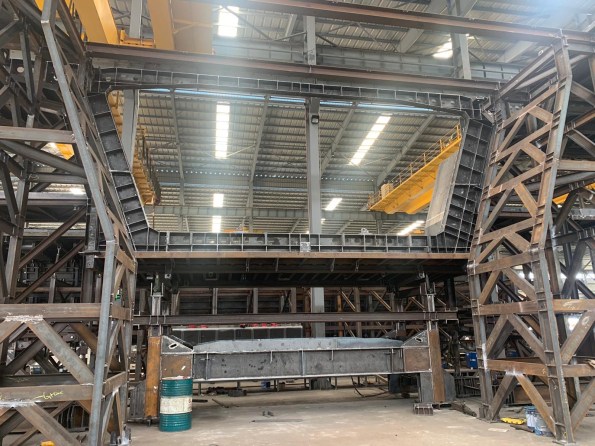
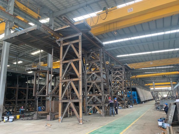
John I remember you telling us in Phase 1 you are always amazed at the scale of temp works that are involved in creating the permanent works. For my project the team are spending AUS $2.5M on establishing and running a precast yard. Below are some pictures from the trial erection currently underway in China of the pre-cast bridge segment forms. The forms are designed to be adjustable to accommodate the curves with the new segment cast next to the previous one to ensure continuity.
The average segment will be 11m long, 2m wide and 4.7m high. I’m not sure what the size the forms are but you can get an idea of their scale from the size of the people in the photographs. I’ll post more detail when they are installed on site and I understand more.

Reflections from the other side of the world…
‘G’day mate’, ‘how you going?’, ‘too easy’ and Struth, it’s hot out here… (ok so that’s enough of the Australian slang from me). Welcome to the first blog post from me on the Batemans Bay Bridge Project. After less than 2 weeks on the project I’m still trying to get my head around the technical side of things so this post will give a project overview and summarise my initial observations.
Project Background
Like me, most of you won’t have heard of Batemans Bay before. Its a small town of about 11,000 people on the East Coast of Australia in New South Wales (see map). To get here you have either a 4 hour drive south from Sydney (170 miles) or a 2 hour (94 mile) drive east from Canberra. The town straddles both banks of the River Clyde with the A1 ‘the Princes highway’ between Sydney and Melbourne passing straight through the town. On the northern side of the town, the A1 meets the B52 ‘the Kings Highway’ which is the quickest route to Canberra and the Australian Capital Territory (ACT). As a result Batemans Bay has a lot of through traffic and has become a popular destination for the Canberra residents as it has the nearest beach.
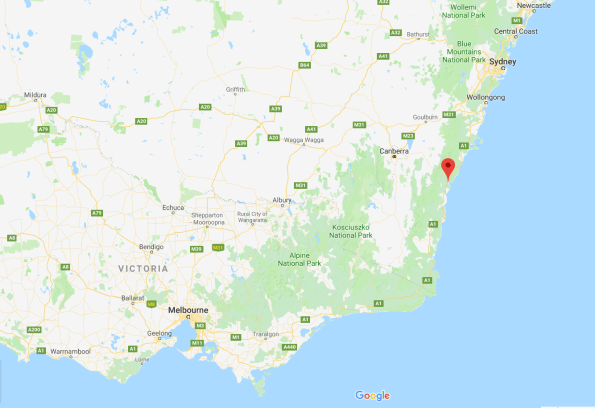
Map showing Batemans Bay location
The existing road bridge connecting both sides of the river is an old 1950s steel truss bridge which supports a single carriageway. It has an unusual design incorporating a central vertical lifting span to maintain marine access upriver (see picture). With increased and heavier traffic flow along the A1, spiraling maintenance costs and congestion from bridge closures for marine access the client RMS (Roads and Maritime Services similar to Highways England) has decided to invest in a new bridge and associated junction upgrades. John Holland’s solution is a joint venture with VSL to deliver a 168 segment precast concrete box girder bridge under a Design and Construct Deed (D&C contract). This construction method was chosen to increase spans and reduce the number of piers following public consultation. An impression of the completed bridge is also shown below.
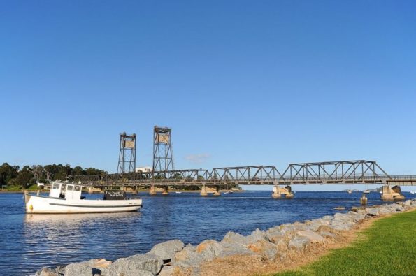
Existing Batemans Bay bridge
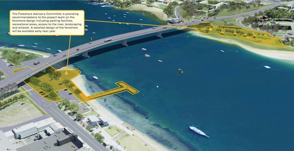
Impression of new bridge.
Further information can be found on the RMS website: https://www.rms.nsw.gov.au/projects/south-coast/batemans-bay-bridge/index.html
The delivery of the project is split into 4 overlapping phases:
Phase 1 – Design, enabling works and service diversions. This phase was due to end this month but has been extended by 3 months after additional works were added to the scope of works to ‘future-proof’ cross-river service capacity.
Phase 2 – Bridge construction. This phase is just getting underway. This week we started the establishment of the precast yard and commenced the first pier foundation pour. Initially, my job will be working as a Project Engineer to establish the precast yard bridge. This is a great opportunity to see a range of engineering including earthworks, piling, reinforced concrete, steel erection and gantry crane installation. Can you tell I’m excited about it?
Phase 3 – Junction upgrades. Elements of this phase will run concurrently with Phase 2. John Holland receives incentive bonuses for maintaining certain levels of traffic flow which will result in a staggered approach to the junction upgrades.
Phase 4 – Demolition and removal of the existing bridge including the removal of all substructure and foundations. Planning for this phase starts next year so if you fancy the job Ash Dale let me know and I’ll make sure your CV gets to the PM…
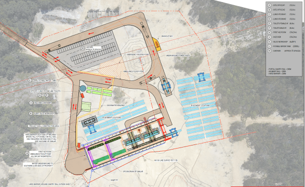
GA of proposed precast yard
Initial Observations
So what are my initial observations after 2 weeks in the office?
- Communication. The Australian construction industry and UK military both have their own slang:
– Slew cranes (mobile cranes).
– Franna cranes (not common in the UK but is used for small mobile lifting operations like a 35t TEREX or RTFL).
– FRP – Formwork, Reinforcement Pour (RC to you and me).
– Star posts (6′ pickets).
It’s definitely worth taking the time to check exactly what is meant by terms you are unfamiliar with to avoid confusion and misunderstanding. Google image search is also a great resource – it’s true, a picture paints a 1000 words and all that! We also have a French contingent from VSL as well as engineers from Asia, New Zealand and the UK. We all use the same technical language which aids communication regardless of the native tongue.
2. Commercial awareness. I’ve been surprised at how commercially involved the engineers are on site and was warned about this by the PM during my arrival chat. Here the engineers are responsible for planning/designing their work packages and resourcing them. For supply of materials this requires a minimum of 3 quotes and a purchase order. If services are required, a short form contract is needed resulting in a tender process. From my initial observations it seems that the majority of the traditional QS role sits with the engineer. There is a small commercial team here who are responsible for approvals, contract negotiation/writing and payments. I’m interested to hear if this matches the experience of the other students on placement as it was not what I expected. So what?
– Advantage: site engineers are more aware of the cost of their works so in theory produce more efficient designs and reduce overall project costs. Reduced costs = increased profit.
– Disadvantages: the organisation is split into various sub-teams working on different parts of the project. With each team resourcing their own packages there are missed opportunities to benefit from economy of scale particularly when there is limited communication between the sub-teams. This results in the duplication of tendering when works across the project could have been combined into one works package. There is also a significant amount of ‘group think’ in the office when selecting companies for tender packages which may not result in best value for money.
3. Drawings. The drawings for the bridge segments are incredibly complex and if I’m honest really blow my mind. Even the pre-cast yard foundation slab and steel shed erection drawings contain more detail than I’m used to. I think Phase 1 needs to cover reading and interpreting engineering drawings in more detail as I’m well behind the standard expected for the role I’m performing on site. Having example drawings at the front of the classroom during project assessments was a good start but I think more time invested in this area would make the Phase 2 transition easier to manage.
4. Military experience. The military environment provides a range of transferable skills that are really useful in the construction industry. From managing people and meeting tight deadlines to technical issues like how to build a bailey bridge (no I’m not joking they are building a bailey/Maybe bridge here) we can add heaps of value. Regardless of what you’re doing two rules remain:
- No plan survives contact.
- Keep it simple stupid.
