Archive
BSRIA Design Checks
Short and sweet post, thesis calls.
I have recently discovered the BSRIA (Building Services Research and Information Association) design check guides. There are a number of booklets for different elements of a building services design (e.g. HVAC systems, variable flow water services, electrical services, etc)
Each guide lays out a map of the design process, lists the relevant standards and legislation and contains a detailed checklist of things to consider. Some examples of the content for the HVAC booklet (the one I am using now) are shown below.
These booklets are used by Bryden Wood to provide a quality assurance record during the design process. They are not freely available, but most design offices should be able to get hold of them. If you need something in particular over the next couple of months then please drop me a line and I can nick the booklet in question off the BW server.
They are an excellent way to rapidly pretend to be an expert on a subject, when you are in fact a clueless Army punter.
Happy thesis writing.
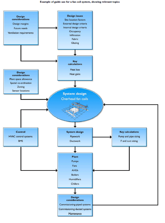
The design process is laid out clearly at the start of the booklet.
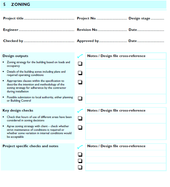
The bulk of the text is a list of checks that prompt you through the design process.

Beside each checklist is a detailed explanation of what to consider at each stage.
British Airways Medical Facility
As my Phase 3 placement progresses I am getting used to the systematic way that the design office undertakes a building services project. This blogs aims to describe the process using a small task I am running with (it is related to aeroplanes – exciting).
The Project:
British Airways have a flight training facility at Heathrow centered around a hanger with a row of articulated flight simulators. The surrounding building contains the plant to operate the machines and a number of offices.
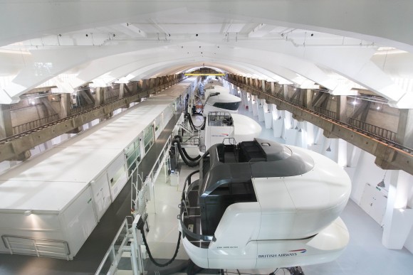
Flight Simulator Hall. I wasn’t allowed to have a go in one.
One office has fallen into disuse so BA has decided to convert it to a medical facility with the following spec:
- Waiting area with seating for six.
- Three conditioned treatment rooms.
- Tea point and unisex toilet.
- All spaces are to be cooled or heated as necessary, supplied with ventilation, hot and cold water and electrical power.
The area is currently used as a storeroom and janitors office – it is unheated and has a number of bits of old air conditioning plant running through it.
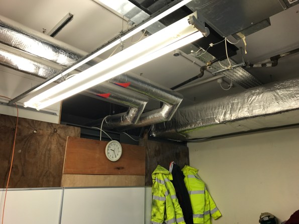
Medical facility – current state. Some homeless facilities manager has been squatting here for a few months, hence the PPE.
Design Process:
The M&E design process at Bryden Wood is almost identical regardless of the size of the project. However, a bit like the combat estimate the cycle is scaled to the time and resources available to the task …. smaller project = less money = less detailed design. With the very small scale of this task the entire plan has to be completed in about a week, giving it the feeling of a Phase 1 design project. Generalised steps to the design are included below:

Schematic of the existing plant room space. Note the Air Handling Unit at the bottom right that the new ventilation design aims to tap into.
Step 1 – Fix the Spec. Meet the client and hammer down exactly what they need and are willing to pay for, bearing in mind that these things are usually decided by different people with very different priorities. During this process I listened to the nurse’s passionate pleas for a tea bar with coffee grinder, zip tap and dishwasher. This has subsequently made it into the design as a sink.
Step 2 – Develop Strategy. This is arguably the stage requiring the most engineering judgement. Decide on what systems are needed to meet the client spec – how it will be heat, cool and ventilate the space. As an example, at this stage I decided to use a wall-mounted unit to provide cooling and piggy-back on a nearby air handling unit to provide ventilation. At last I can now sleep at night.
Step 3 – Calculate Room Loads. Work out the worst case cooling loads (people, lights, solar gain, and equipment on the warmest day) and heating loads (empty room on the coldest day). Add 15% extra capacity for future expansion, wear & tear, etc. Follow a similar process for hot water and ventilation rates. This is easy, bread and butter stuff following CIBSE guidance and rules of thumb.
Step 4 – Speak to Manufacturers. Talk to our favorite manufacturers (the ones who buy the best free lunches) and ask them to quote for the systems needed.
Step 5 – BIM Modelling. Model the selected systems in Revit (the chosen Bryden Wood BIM programme) and ensure there are no clashes with the existing sites systems. I usually outsource this step to an apprentice CAD draftsman who uses Revit like he is plugged into it Matrix-style.

New room ventilation plan. This sketch is handed to the Revit techie who turns it into a sexy model for the client to peer at.
Step 6 – Paperwork. Complete the diligence paperwork required to provide we have met the Principle Designer responsibilities and manipulate the Revit model to produce the final design drawings. Sit back and enjoy tea and medals.
Building Energy Efficiency
How do MEP engineers design a building for energy efficiency? This was a question that had often kept me awake at night…. fortunately thanks to the first few weeks at a design office I have an idea of how the process works. This blog will briefly run through the process of designing the building MEP to specify equipment and meet the UK energy efficiency (Part L) building regs.
Building thermal model in IES – Hevacomp for grown ups
First of all some principles of how the design office operates (so far):
- Minimise time. Time is money for the design office; they are very fastidious about budgeting time to a project in advance and accounting for the time spent. Therefore only the minimum design work is undertaken. g. pump size on the longest pressure drop, don’t both with checking anything else.
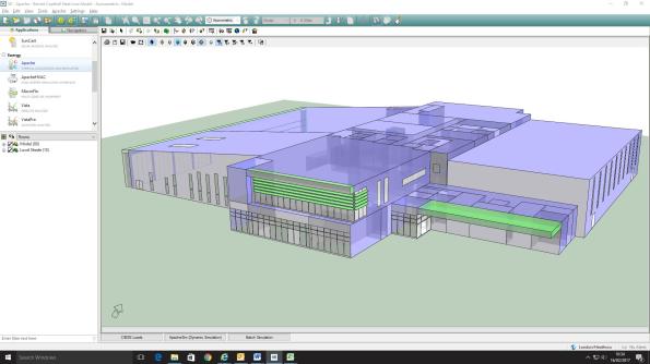
- Deliverables drive the project. In conjunction with the previous point; Bryden Wood will only produce a model when they are required to do so, otherwise Excel is generally used to do the job. In my first project the client has paid for a Revit model update every two weeks, but all equipment sizing is done on Excel. The data in this model is minimised to limit time wasted; for example pipes are shown uninsulated as it would take time to draw it on, drawings are not colour-coded, etc.
- Energy Efficiency Legislation is met (just). There is no advantage to the client of smashing the energy efficiency legislation… this would just waste money. The equipment and building materials have been spec’d to meet the legislative requirements and no more.
- Minimise Responsibility. The MEP team is only able to influence a small element of the overall building performance; designing MEP equipment. Unfortunately we are required to predict the entire building performance – which is influenced by the number of windows (architects), orientation (arch), structure (civils), etc. Therefore time is spent recording other stakeholder’s decisions to protect BW if/when the building fails the performance checks.
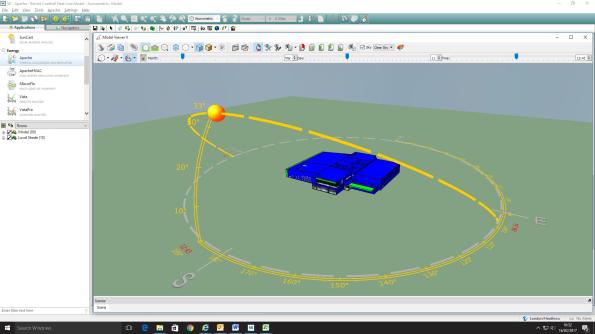
Sun path graphic for Barnet leisure center. The program will include solar gains for rooms.
My first project has been the MEP fit-out of two leisure centres in North London. In very simple terms the design process has been:
- Develop Strategy. A scheme for the MEP design is developed based on building use and client wishes. This is generally based on experience within the design office and the clients’ spec; for example the swimming pool will be served by an Air Handling Unit (AHU), Café will have underfloor heating, etc.
- Rough Equipment Sizing. This is undertaken on a big Excel spreadsheet with details of temperatures, room internal heat loads, fabric losses etc. All very reminiscent of the PEW design exercises, based on CIBSE or ASHRAE references. Loads are summed (with a bit of fudge factor diversity) to give approximate plant loads for the building.
- Select Manufacturers. The client has a list of preferred manufacturers who get involved with selecting the equipment for role based on the rough loads calculated above. This stage has an element of project management to it, and a few free lunches.
- Develop Thermal Model. Dedicated Integrated Environmental Solutions (IES) software is used to model the thermal characteristics of the building, in parallel to stage 3. This adds more accurate numbers to allow detailed plant sizing and includes solar gains, heating profiles, etc. The full potential of this software is not used to save time – for example, instead of modelling the transient (or warm-up load) for the building the equipment is sized on the steady-state load +15%!
- Confirm building meets Part L. The IES program is one of four approved to determine whether a building will meet the legal efficiency requirements. Detailed system information is added once plant has been selected, then the program produces an Energy Performance Certificate (EPC) and Part-L compliance certificate.
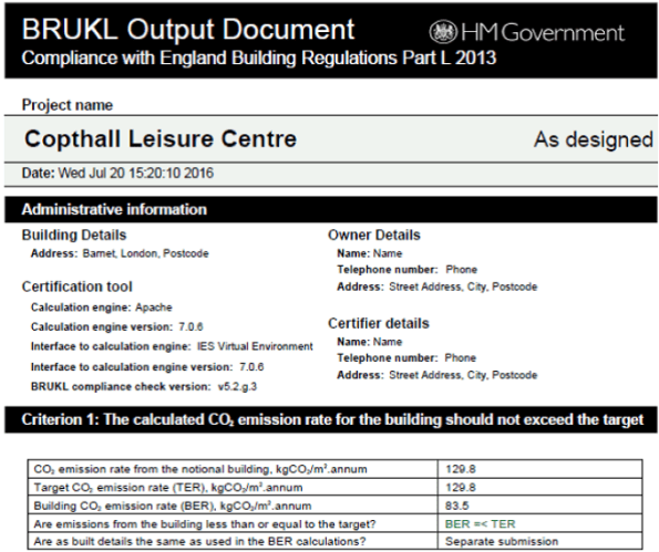
The finished Part-L compliance report
In all this process will have taken a team of three about 12 weeks to complete… a bit more relaxed than the single week we are given on the building services design exercise at PEW.
Bryden Wood Technology Ltd
I have put my nose back to the grindstone after a short cameo as a ski instructor, starting my design office placement working for Bryden Wood Technology Ltd; a small design consultancy of around 130 people based in North London. The practice is focused on architectural design; however has a MEP team of around 20 who handle both the technical elements of multi-discipline projects and some stand-alone MEP projects. This blog is a short intro to what I will be doing over the coming two months.

My approach could be called unique….. It certainly isn’t efficient at the moment.
The first project I have got involved with is the construction of two leisure centers in North London; Copthall and New Barnet. Both jobs have progressed to ‘RIBA stage 3’ (developed design) by a different contractor and over the next couple of months our team will move it on to the next stage, producing a detailed technical design. So far this process seems like a chilled-out version of the PET building services project; producing the loads, air changes and lighting requirements for each room and sizing plant and luminaires to meet the demands.

Anyone for a swim? North London…. bring a stab-vest.
I have been occupied for the first week designing the fabric of the building and selecting equipment to fulfill the requirements of Part L of the building regs (fuel and energy efficiency). The output of this process is a building energy certificate (or EPC) which is required to allow planning consent to continue as well as provide operating information for the end users. This is all carried out on a government-approved computer program called IES, which is basically a modern version of Hevacomp for grown-ups. Like much of the work in a design office, you are not efficient until you are conversant with the CAD.
The project is a big one for the MEP team, containing a chemical dosing and UV installation (for the swimming pools), a small CHP plant and a rooftop solar array. The project is fully ‘BIMed’, and uses Revit and subsequently Navisworks as the main platforms to accomplish the design co-ordination. The project is forecast to finish by the end of March – it should be a good exercise to get used to the CAD programs and the processes that take place in a design office.

Diesel generator + exhaust hot water heater = fuel efficiency. Doesn’t come cheap though.
Its early days, but so far the design office has been a bit of a culture shock compare to the site placement; to compare notes with the other ‘PETs’ I include some initial impressions:
- The nature of the work is very compartmentalised and ordered compared to the site placement. The hierarchy is well established and roles are well defined; with the discipline directors in immediate contact with their project teams. It seems it will be very different to the firefighting I became accustomed to on site.
- The financial aspect of a design is well defined; the company carefully measures the effort it expends on each project and scales effort to the agreed fee (generally fixed price); it is a big deal to ask for extra cash from the client. Again in sharp contrast to Crossrail!
- The office is simultaneously dealing with a large number of projects (in excess of 50); a number of these designs are scoping or concept only and will not be built; this is particularly the case for jobs in the pharmaceutical industry.
- The majority of the work is dictated by design standards, building regulations, codes of practices, etc.
- A lot of the thinking is done by computer programs which are not that intuitive to use. Hand calcs are done for initial estimates only, on a spreadsheet.
- Google Sketchup is awesome and industry uses it a lot…. This is likely to be the only program I can remember how to use when I come back to the Army.
Happy New Year
Contract Incentive?
Apologies for another post in such a short period from my last one; I will try and keep it short. In the last month the tunnel vent project seems to have reached the ‘money grabbing’ stage that Gregg and Steve described in their phase 1 lectures … the budget has run out, instructions have dried up and the client (Crossrail) is looking over our shoulders.
In contrast to many projects for commercial clients the Tunnel Vent NEC 3 ‘cost plus’ agreement is geared to incentivise quality above programme, cost or anything else. Therefore, bizarrely, there are no programme-linked milestone payments or costs for over-runs; all that the contract allows for is the reduction of the contractor’s fee. This is illustrated in the graph below (the risk element covers insurance costs):
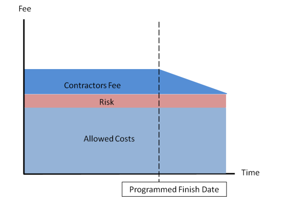
ATCjv cost profile showing tapering reduction in fee past end date
The main way the client is looking to claw back funds is to find disallowed costs… basically finding evidence that we are incompetent or cutting corners. As a result at the point of the project when the contractor (ATCjv) should be concentrating most on the installation phase we are instead trying our hardest to cover our tracks with EWNs and hide mistakes behind other contractors delays.
I’m not sure how many sites would finish on time if their incentive scheme was set up in this way? I look forward to see if the Elizabeth Line opens on time in summer 2018….
Dealing with Delays
The pace of work is speeding up as I reach the last month of my phase 2 attachment. Excellent news *insert sarcasm*.
The finished Bond Street East shaft structure should now be complete to accept tunnel ventilation equipment; cut-away graphic shown below.
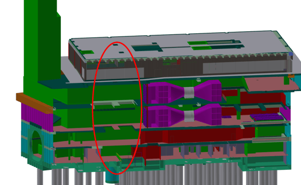
Graphic of the station structure; the ventilation equipment is shown in purple. The red oval denotes a gaping hole currently being filled by the civil contractor (see next photo).
The station structure was due to be complete by Aug 16; however the current site still has no roof, no lights, unsealed walls, etc; as shown in the figure below.
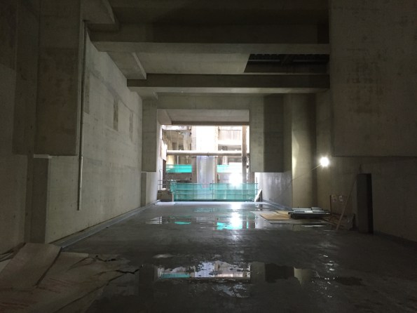
Tunnel vent fan room, missing the end wall (see previous image) and some weatherproofing, paint, permanent lights, etc….
As a result of this delay the mechanical install (by ATCjv, my placement company) has to happen concurrently with the remainder of the civil works to make sure the trains can start running on time. The past few weeks have therefore been dominated by ‘collaborative planning’ to mitigate the civil contractor’s delays. I have eaten through a couple of packs of post-it notes and a lot of coffee to achieve an integrated 8-week plan that both sides agree on, see below:

This is all to achieve an interface control document (ICD); a kind of access and working contract where ATCjv mechanical works are installed in another contractors site Prime Contractor (PC) area. The process has also been a contractual minefield as the ATCjv works information assumed we had uninterrupted access to the entire structure.
The handover process should follow these steps:
- Civil contractor finishes structure.
- ATCjv accept structure and conduct a condition survey.
- Both sign an ICD and ATCjv start installing mechanical ventilation kit.
The actual process has been:
- Civil works delayed by >5 months.
- ATCjv have to start install to achieve Crossrail opening date, 2 weeks of collaborative planning commences.
- ATCjv rinse Crossrail (the taxpayer) for compensation events. ATCjv hide all their delays behind the civil contractors problems.
- ICD signed and mechanical install starts
It has not felt comfortable knowing that I have been part of the dodgy contractor game of blaming all our problems on a third party and getting a wedge of extra money out of the client/taxpayer…. welcome to construction.
On a brighter note we have achieved actual mechanical installation at our Tottenham Court Road site; one gantry crane installed and commissioned on programme. However, I can’t help but feel out-done by the size of Jo’s man-size crane.

Contract vs Common Sense
Over the last few weeks the tunnel ventilation team have been battling the Bond Street Station (BOS) prime contractors on the captivating topic of ‘floor screed’. I think that this is a good example of working to contract rather than common sense… one of many examples on site.
The station design includes a non-structural screed finish to the plant room floors. The main items installed in these rooms are the permanent vent fans, weighing 9 tonnes each. The fans will be in situ for a design life of 25 years, and impose horizontal (thrust) and vibration loads onto the structure through floor fixings.
Tunnel vent fan (Horizontal Installation)
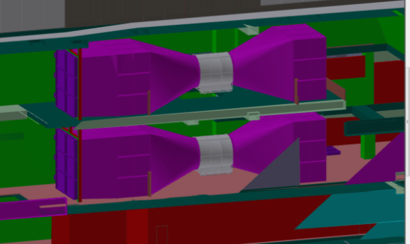
Graphic of the fan installation at Bond Street. The peach-coloured floor is currently being covered in a non-structural screed.
It doesn’t take a civil engineer to see that a non-structural screed will not stand up to this punishment for the station design life. However, despite numerous meetings pointing out the issue the station is carrying on regardless, and this week poured the screed for the plant room floor.

Image of the non-structural screed – note the lack of reinforcement. Please excuse the terrible image quality.
Why is the Bond St station working like this? A few theories:
- The contract incentives are linked to a finished room spec. It is easier to re-work than change the contract, as the commercial department works at a glacial pace.
- It is a lot of effort to search out the information on tunnel vent equipment, and involves liaison with my team. It is easier to claim ignorance, throw the screed finish in and then get money from the client (read taxpayer) to sort it out afterwards.
- The station construction is currently running with about 4 months delay; being instructed to strip-out finished work gives them a solid ‘arse covering’ excuse with the client.
The main contractors are rigidly working to the contract, and the client is unable to co-ordinate all of the separate designs and interfaces between contractors due to the sheer volume of work. I don’t think the client is innocent in all of this, they are slow at issuing instructions and slow at issuing notices to stop.
I expect they will be taking a concrete saw to the brand new floor covering in the middle of next week. Welcome to Crossrail.
Testing & commissioning
After a long delay the Crossrail tunnel vent team have finally completed a project in my patch, all be it only a temporary installation. The temporary tunnel ventilation (TTV) was supposed to complete by the end of Jun, but was finally finished on the 18th Aug; six weeks late on a three month programme. This blog describes the issues that caused the delays and the process of testing and commissioning.
The Bond Street temporary tunnel ventilation will be in continuous operation for over 18 months and is designed to apply fresh air to the running tunnels for construction ventilation at a design rate of 200m3/sec. The four fans are now installed at the -5 level within the Bond Street station construction site. They supply fresh air to ventilate the construction works within the running tunnels.
Plan view of the Bond Street Station TTV installation at the -5 level.
Despite some site access issues the mechanical install was completed to schedule. However, the station main contractor (Costain-Skanska JV) was responsible for the temporary power supply to the installation. They encountered the following delays, mostly due to poor planning and co-ordination:
- The main incomer to the site (from the District Network Operator) was installed with a different phase rotation to the rest of the site. The DNO is a law unto itself and would only come back to site to fix the problem on their terms; this relatively simple process caused CSjv a two week delay.
- The main supply cables to the fans were sized on a ‘back of fag packet’ estimate by an untrained installation contractor. The calculations were not checked by the main contractor electrical installation management. The cables ended up being undersized by about 20%; this required another 250mm2 cable to be run through the running tunnels to supply the feeder pillar, resulting in another 2 week delay.
- The temporary supply cables feeding the vent equipment were supported on the site hoarding; the weight of the cables caused the whole edifice to bow inwards towards the site. Once discovered by the site temp works co-ordinator this installation was condemned and a bespoke cable route had to be constructed. Another 4 week delay.
- The site electrical distribution protection was set to 25% of the circuit breaker (CB) rated power of 1600A. Each of the four fan motors draws 350A at full power. As a result the total power drawn was 4 x 350A = 1500A, way more than the CB setting of 400A. As the fans were run up beyond ¼ power during commissioning the CB cut the supply under load (making a sound like a bomb going off). It took another four days to find a specialist who could adjust the incomer CB to the correct setting.

The DNO searching for the phase rotation problem behind the site main transformer.
When the system was finally energised on the 16th Aug we instructed the vent installation contractor (Hargreaves Ductwork Ltd) to commission the system. Surprisingly, this was not a particularly high-tech process and followed a logical order of testing the safety systems first, then functioning of the fan motors before testing the air flow rates. The stages undertaken are outlined below:
- Emergency stop test. The fans were run up to 25% in pairs before hitting the remote emergency stops at the guardroom. No issues here.
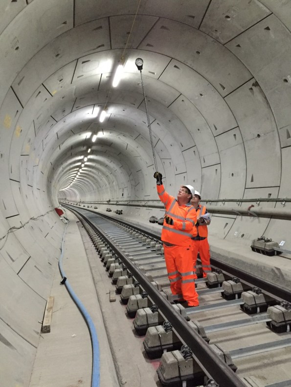
- Fan Vibration Tests. The fan motors were started and tested for vibration using a handheld accelerometer. This measures the peak acceleration in all three axes. The peak values were recorded to compare against the readings at the first service interval in six months’ time.
Airflow path going down through the station structure.
- Fan Air Path. The fan motors were run up through 25% increments to 100% to see if the flow created had any adverse effect on temporary works and debris in the site. At full power the air drawn in through the station was moving at 20 m/s – very windy. This flow was enough to pick up lumps insulation material from two levels above and send it through the fan blades!
- Tunnel Air Flow Rates. The airflow rates were measured from a simple average flow using a anemometer in a grid pattern in the tunnel cross-section, as illustrated in the image below.
Big Ralph using the flow rate measurement grid.
Completing the T&C process marks the end of the temporary tunnel ventilation construction. The installation has been a useful dry-run for ATCjv and our sub-contractors as it has highlighted a number of issues posed by working in an underground site and within the rigid Crossrail quality control procedures. These issues can now be anticipated for the larger scale permanent ventilation installation that is currently ongoing.
On another note is hasn’t been all work and no play. Gary Jackson and I entered a navigation competition in an RAF aircraft and won it! The prize was presented by the Duke of Edinburgh, see below. Most importantly the event included a free bar…

Big Phil presenting a big prize.
Pumping Iron – Not as hard as pumping Concrete
It turns out concrete can be pumped – I have been surprised how far it can be pumped if you try hard enough. The Bond Street East site contains a batching plant at Hanover Square (next to Oxford Street) feeding a pair of chunky concrete pumps. These then feed vertically down a 5-story temporary pipeline to a massive thrust block tied into a group of RC piles by big steel beams. This block enables a 90o turn before the pipe travels another 1.1km along the running tunnels to the track work sites.

Batching plant surrounded by some very expensive flats. I hope they appreciate the token acoustic sheeting.
The scale of the temporary works on these sites is fairly mind-blowing. I sit opposite the guy responsible for making this pipe work; I can assure you it is blowing his mind as well.
Concrete pipes descending from the surface to level -5
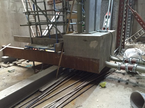
The daddy of all thrust blocks enabling a 90 deg turn.
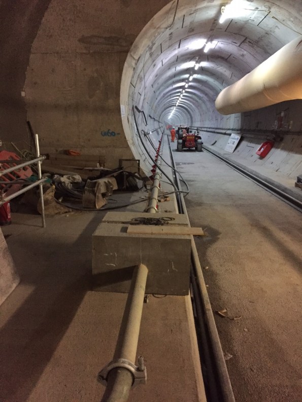
Concrete pipes disappear off into the distance to the work sites.
Unfortunately the scale of the project also creates a lot of inefficiency and interface issues. The above-mentioned pipes had to penetrate a ventilation bulkhead we had erected in a feeder tunnel. Despite being part of the same Joint Venture there was no co-ordination put in place between the teams, leading to a chest-beating discussion about who had the priority. Needless to say the concrete-pumpers won and we had to strip out our bulkhead, only to re-erect it this week. Hopefully the new-fangled BIM will put all these issues to bed. We live in hope.
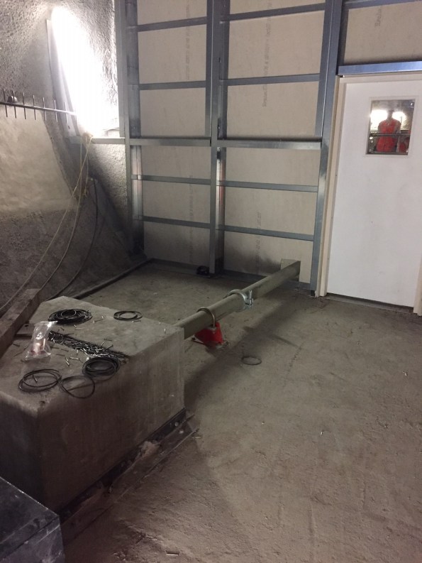
Ventilation bulkhead, version 2. Please ignore the photo-bomber in the window.
In other news I have occupied myself with a bit of ‘commercial awareness’ by firing a magazine of EWNs at Paddington station and following them through the commercial department. Not as interesting as it sounds.
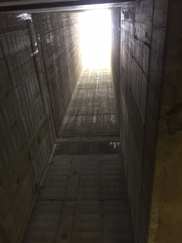
We have also been lifting in some 2m x 2m x 3m silencer pods to the -2 level through the only route big enough to take them; a 5-storey vent shaft. Unsurprisingly it lost a bit of galvanisation from the corners on the way down.

Big steel box + no tag lines = swinging load. It bashed the rim of the shaft on the way in but was ok when it was inside the shaft.
The Crossrail Oil Tanker
In keeping with my esteemed colleagues I am joining the post-AER blog party.
The scale of the Crossrail project coupled with the number of stakeholders involved leads to an awful lot of inertia within the organisation. To push a bad nautical analogy the Crossrail oil tanker makes the British Army bureaucracy feel like driving a particularly nippy frigate.
As part of the tunnel ventilation contract ATCjv has to justify the access and maintenance strategy for the end user (Rail for London, the Crossrail arm of TfL). This includes ensuring the designs allow for the replacement of equipment during the 100-year design life of the stations. I have been attempting to re-write the access and maintenance strategy for a system of dampers installed in a 3 x 3 grid against wall openings at the Paddington Station platform level.
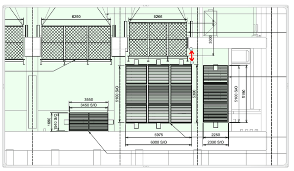
A drawing showing the damper installation – the space available for an access and maintenance crane is shown by the red arrow.
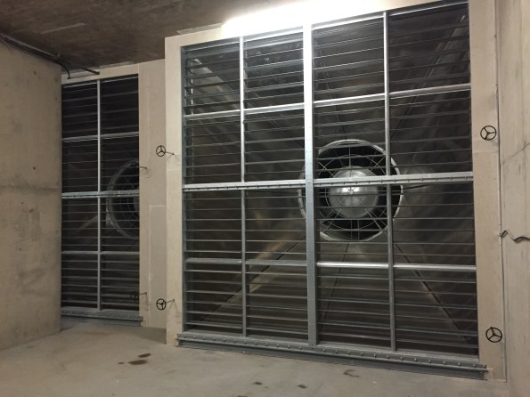
Some similar damper banks installed at Bond Street station
The means of replacement of these damper units was a scope gap in the initial works information for the station contractors. As the stations are running well behind schedule this scope has been moved over to ATCjv on a ‘Cost +’ contract. This is clearly a lucrative deal for ATCjv that has not incentivised the company to seek a low-cost solution in any way. The resulting design is for a series of gantry cranes to allow the replacement of the dampers.

Kone gantry crane in Canary Wharf station – similar to that proposed for the damper access and maintenance strategy.
In the case of Paddington station this solution is not suitable for the following reasons:
- There is no space for the gantry crane on the downstand beam (see drawing detail at top and below).
- The gantry crane would not be able to access the top of the damper frame to remove it (making the whole installation pointless).
- It’s a massively expensive solution to a simple problem.

Gantry crane proposed design. Damper units are the pink louvers in the 3 x 3 grid, crane outline is shown in red. Note the position of the crane hook is below the top flange of the uppermost damper unit leaving no allowance for slinging the load.
Rather than mess around installing and then maintaining a series of electric cranes I am trying to justify using a portable material lift instead:
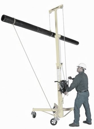
Mechanical material lift, kindly modelled by Mr Tom Docker
Here lies the oil-tanker. Getting this solution approved has required meeting with the end user, maintenance staff, station main contractors, crane installers and Crossrail representatives. The justification has included a feasibility study, cost-benefit analysis and a new access and maintenance strategy. This process has been ongoing for two months, and will hopefully be concluded before I depart for phase 3.
The scale of commercial manoeuvring and arse-covering has been pretty impressive and has given me some pretty good insights into the importance of writing a tight contract instruction. In this way Crossrail could have maintained focus on a simple and common-sense solution to prevent the problem running away into a taxpayer money-pit.
I am guessing that everyone will have a similar example from their own sites; has anyone been successful in actually putting an issue like this to bed?
Mark
