Archive
Obvious Mistake II
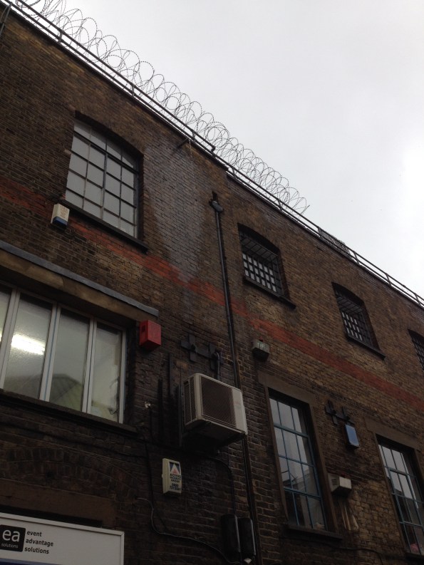
On the same vain as Rich; spot the obvious mistake in this budget E&M installation. It amuses me every day as I walk to work (whenever it rains).
To PC or not to PC…. That is the question.
Sorry about the title. This blog is about the issues surrounding working on someone else’s site; something it seems that M&E engineers have to put up with a lot.
The work being carried out by my employer (ATC joint venture or ATCjv) involves installing a long term temporary ventilation system to replace a slightly cobbled together short term system – please see earlier blog. This involves fitting out most of the bottom floor of the station (level -4) with four ventilation fans, ducting and associated attenuators and dampers. See image below:
Temporary Ventilation Fan Installation
Co-ordinating the installation process has occupied most of my time for the past month. It involves threading the equipment through the existing ticket hall structure, most of which is still an active building site. As you can imagine this creates a nest of interfacing problems with the main site civils contractor, Costain-Skanska Joint Venture (CSjv).
The CSjv site is running to its own schedule and is unwilling to give up an inch of it to allow the tunnel ventilation works to go in. They have taken the step of insisting that ATCjv take Prime Contractor or ‘PC’ responsibility of our work area; leaving the unusual situation of a ‘Russian doll’ arrangement where we own and run a site four stories underground inside another separate site. The extents of the ATC site are shown below:
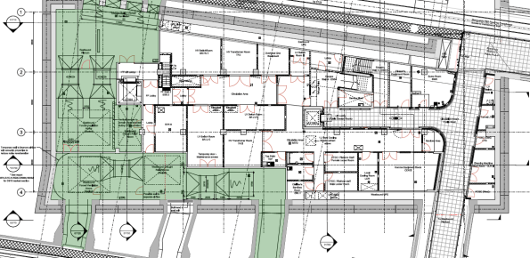
The ATC site shown in green (four floors underground in the CSjv basement)
The process of setting up the PC area was not smooth. Any readers who have yet to undertake the SMSTS course may be in the dark as to the requirements of holding PC of a site. The full requirements are on the HSE website here:
http://www.hse.gov.uk/construction/cdm/2015/principal-contractors.htm
Keeping it as brief as possible the PC is the ‘duty holder’ of legal responsibility of the site; they are required to produce and assure the health and safety of the workforce, compliance with environment and noise regulations, secure the site and provide welfare. The end result is a substantial pile of paperwork that no-one will ever look at unless an accident happens.

PC Paperwork. It’s what I joined up for.
I found it interesting to consider the depth and detail of site paperwork compared to that I remember being in place on RE construction sites.
The idea that ATCjv can setup and run a complete site in the middle of another fully functioning site is a bit silly. When that site is underground it is very silly. However, ATCjv have been instructed by Crossrail to do so: his brings around an odd situation that to use their welfare facility the workforce has to walk 1.1km along a tunnel and then climb to the surface to use the toilet (in reality they just find a dark corner of the tunnel!)

The Site Welfare Facilities
Digging slightly deeper (excuse the pun) it seems this arrangement has come about because the first work group to enter the site from ATCjv were roundly regarded as “cowboys” and managed to get a Crossrail H&S warning raised against them. The CSjv site basically looked for any way to transfer the perceived H&S risk over to ATCjv; this has then caused nearly two years of paperwork hassle for ATCjv to run and administer a completely separate underground site.
It seems that in construction first impressions are everything.
Calling all aspiring structural engineers
Evening all,
A short and sweet post. As a lowly E&M engineer in training I am interested in some second opinions on the deflection of steel structures under load.
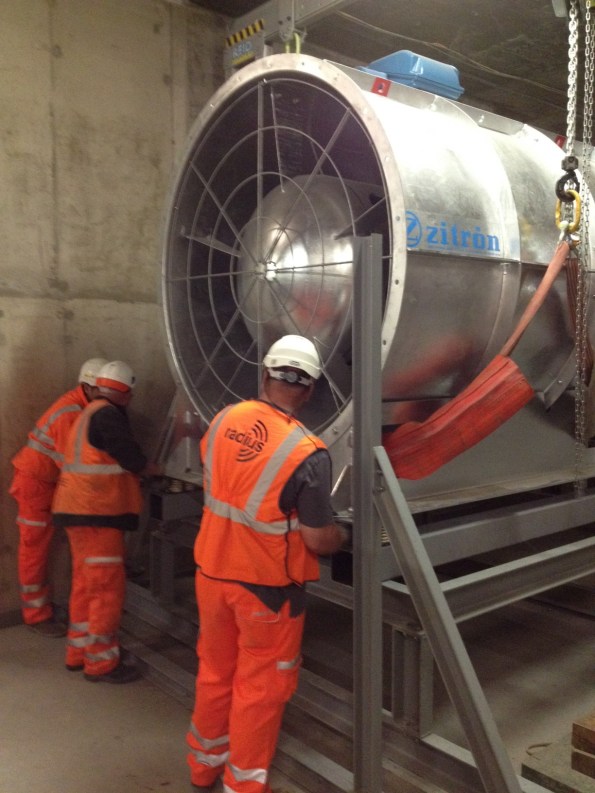
This week I have been occupied with installing temporary tunnel ventilation fans in the -5 level of Bond Street Station. The fans weigh around 3500kgs and will be in operation for around 18 months. The first of four fans was due to be moved into place today using a porta-gantry onto a simple steel frame.
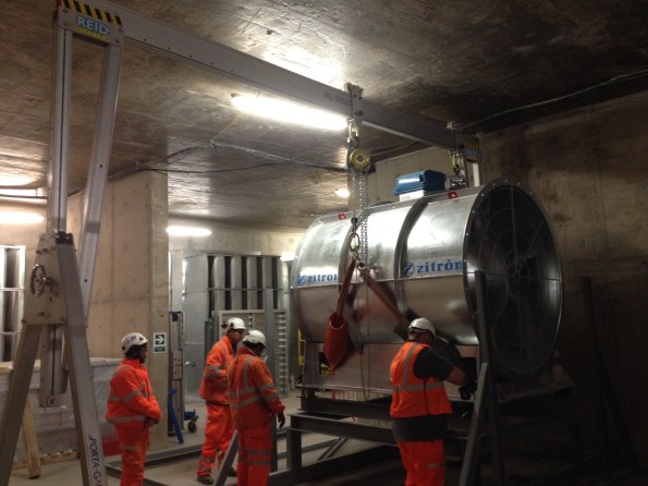
The fan being lowered into position on the support frame
Upon lowering the fan onto the support one of the operatives spotted a part of the frame deflecting under the applied load. The web of a channel section was bending inwards as the chain hoist lowered the fan, distorting the anti-vibration mounts.
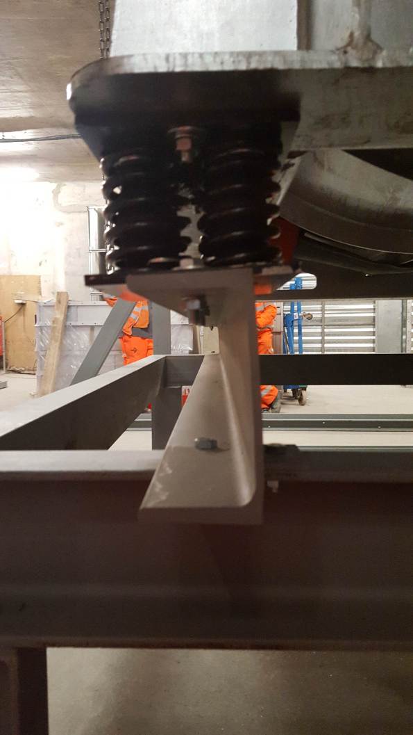
Apologies for the poor photo. If you draw a line along the top and bottom flanges of the C-section they are no longer parallel; causing distortion to the anti-vibration mounts. The lift was stopped before the full load was applied.
This would all be highly interesting except for the fact that I am only SMSTS qualified person on site and conducted the brief for the works. It also came down to me and a grad mechanical engineer to judge whether the deflection the channel was showing was acceptable, and whether to continue lowering the full load onto the deflecting frame. After some teeth sucking and discussion with the lift AP we decided to lift it back off and question the frame designers. Queue a lot of Northern blokes pissed off that they had wasted a days’ work. Reminds me of being a Troop Commander.
On removing the load the channel returned to its original shape with no permanent deformation.
Was it the right decision to stop the lift? Or can you expect visible deformation on a channel loaded in this direction? Is this the right steel section to use for this application?
Temporay Tunnel Ventilation Problem
As well as getting my head around the intense amounts of jargon I have been occupying myself with a problem facing the tunnel ventilation team.
Here is the BLUF: Each tunnel (East and Westbound) contains a couple of dirty diesel-powered locomotives and a workforce occupied with drilling holes in the wall. The upshot is that the air quality in the tunnels has the potential to become very poor as the M&E fit-out work progresses, and the permanent ventilation system is a year away from commissioning.
My placement company (ATCjv) are charged with the temporary ventilation to prevent this becoming a big problem. Unfortunately they are also preoccupied with the permanent M&E fit; as a result the temporary works are getting relatively little attention. The permanent ventilation fan system is eventually designed to provide 100m3/s into the tunnels at each station when running at steady state; in the case of a fire or terrorist gas attack it can blow or suck 600 m3/s at full whack. This is enough to create a 9.6 m/s (21 mph) draught down each of the two tunnels.
However, whilst each station is under construction the main ventilation fans are months away from being installed; the ATCjv ventilation team need to provide a flow from Bond Street station to give sufficient air quality for the workforce in the tunnels. The flow diagram of the temporary ventilation installation is shown in figure 1.

Figure 1. Bond Street section temporary ventilation flow diagram
The interim solution at Bond Street station until a large-scale temporary system is commissioned is to fit a 250 kW forced ventilation fan into a tunnel feeding the main running track, an image is shown in figure 2. The flow rate of ventilation air through this fan is measured using an anemometer held in the flow– not a particularly scientific or reliable method. Ideally the temporary solution will give a flow rate that is comparable to the finished station; the current measured flow velocity in the fan jet is around 24 m/s, giving a volumetric rate through the fan (velocity x area) of 8.64 m3/sec. This is way too low to meet the temporary requirement of 35 m3/sec. The solution is to rely on the noxious gas detection equipment with the workforce in the tunnels as a safety net and take the problem ‘on risk’ (i.e. no-one important has noticed yet).

Figure 2. The temporary ventilation fan in its feeder tunnel.
The final ventilation system will be commissioned with a much more rigorous ‘grid’ system of anemometers to measure the flow velocity throughout the tunnel cross-section (see figure 3 below) which will give a much more accurate flow value. However this hasn’t been applied to the temporary system – it is too expensive.

Figure 3. Approved tunnel ventilation measurement methodology. Survey points on tunnel cross-section show anemometer locations.
To keep myself useful I have tried to figure out a more accurate figure for the ventilation flow than given by the current improvised method. The ducted fan acts to fire a jet of high velocity air down the centre of the tunnel drawing further air with it from the surroundings (air entrainment). This has the effect of increasing the airflow down the passage. To add some detail I have tried to improve upon the simple flow model by considering an annular boundary layer around the ‘jet’ of high-speed air, as shown in a dodgy sketch below (figure 4).

Figure 4. Flow pattern from the ventilation fan, back of fag packet version.
V1 in the image above is the peak flow at 24 m/s, with the air velocity at the edge of the fan ‘jet’ being 8m/s. Using this new approximation a revised estimate of the actual flow taking into account entrained air through the 3-meter wide tunnel is 19.32 m3/s. Still off where it should be, but a little bit closer to the desired 35 m3/s. The construction manager posed with this solution was simultaneously pleased that it was larger than his number and completely unconcerned as to the reasoning behind it.
I hope at least Mark Hill was happy that I actually tried to apply some of the knowledge he threw at us in the second half of last year. Please consult Palmer TMR 1 for a more detailed description of where this figure comes from…. if you can stay awake.
Crossrail Tunnel Ventilation Team
My feet are now well beneath the desk and am getting stuck in with my attachment within the Alstom, TSO and Costain joint venture (ATCjv) working on the Crossrail tunnel M&E fit-out contract (contract number 610, shortened to C610). The aim of this blog is to briefly outline the role of my team and my tasks over the Phase 2 placement.
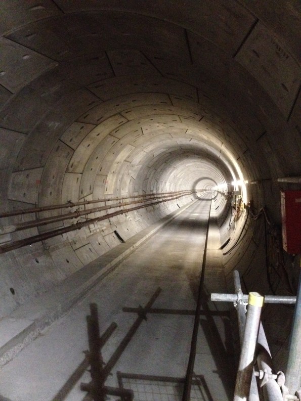
Figure 1. Another day in the office, looking East from Canary Wharf – the only station remotely on schedule. Note the absence of any building services!
C610 Team
The team consists of around 80 engineers, supply chain personnel and construction managers. The C610 contract and associated track power contracts total a third of the entire Crossrail budget (in the region of £350M over six years). In contrast to the other discrete station sites the C610 contract deals with the entire tunnel system (all 22 km) and needs to interface and deconflict with 14 separate stations and ventilation shafts; each with their own principle contractor. Standby for future blogs and TMRs regarding PC interface issues….
The C610 elements include:
– Tunnel ventilation.
– Tunnel drainage.
– Tunnel overhead lines.
– Tunnel fire and LV power installations.
– Temporary works during construction (e.g. temporary tunnel ventilation, construction power)
Paddington Station
I am part of the permanent tunnel ventilation team and have been designated the lead engineer responsible for the construction planning and installation of the equipment for Paddington station. I feel well prepared for this task as I once managed the build of a toilet block in Kenya. All tunnel ventilation systems are embedded within the station designs; requiring the M&E works to take place within another Prime Contractor’s’ jurisdiction.
The Paddington installation includes:
– 6 x 250 kW axial forced ventilation fans (each fan weighing 8.8 tonnes).
– Associated power-operated dampers, attenuators, transitions and ductwork.
– Variable speed drives, control system and SCADA interface.
– 11kV power supply.
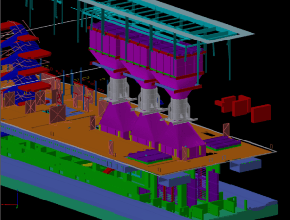
Figure 2. CAD Image of Paddington station with station box cut away. The fans are shown as silver cylinders with ducting transitions and dampers shown in purple; the blue stairwell at the left of the image gives a sense of scale.
The role will include managing suppliers, the site owners/prime contractors and installation sub-contractors as well as planning the logistics of the task in a congested London site. As construction actually starts at Paddington in Nov this year I will also be on-site working as part of a team of three engineers managing the installation of the identical ventilation equipment at Tottenham Court Road and Bond Street stations. Surprisingly I am the oldest member of the team at the tender age of 30! This work started last week, and will allow me to ‘tick-off’ a few more of the CEng competencies in the near future, as well as identifying all of the problems for ‘my’ station late in the year.
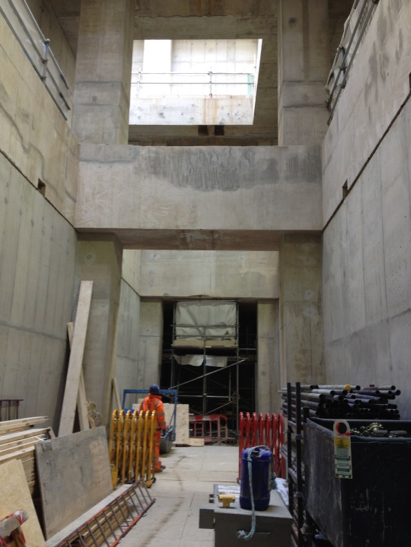
Figure 3. Fan halls waiting to be filled with shiny new M&E equipment; photo taken at ground level -3 floors. Not the tidiest site I have ever seen.
Otherwise, the attachment has started with a swift pace and no shortage of work to get my teeth into. Also, one of my team happens to be an Aussie – I welcome any cultural advice from my colleagues in the Southern hemisphere.
Regards,
Mark
PEW Does Tough Guy
Original article written for Sapper Mag:
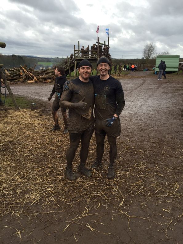
On Sun 31 Jan 16 members of the Professional Engineer Training (PET) course embarked on the ultimate test of civilian toughness – Tough Guy 2016. Four elite members of the cohort were selected to compete; Captains Grant, Kiddie, Palmer and Parton had trained for literally hours and were in peak physical and mental condition as they journeyed over to the exotic lands of Wolverhampton for the event.
For those unfamiliar with the Tough Guy Concept the event calls for competitors to cover 15km of cross-country running interlaced with wet and muddy obstacles and hill sprints. The theme for this year was “The Somme” with the course culminating in an obstacle course named the ‘Killing Fields’ with electric fences, burning hay, concrete tunnels, a lot of cold water and endless mud.
 Morale remains high for Kiddie and Grant.
 The ‘Toughened’ PET team celebrate.
Unfazed, the team donned their lycra, neoprene hats and X-Country trainers and fought their way to the front of the 3000+ people starting the race. At the starting cannon the team was immediately split into two groups and ran hard to get to the front of the pack; myself and Capt Parton found ourselves in a group of crazy Germans and Danes who remained with us for the rest of the event. The next 10 miles blended into a haze of throbbing legs, ice-cream headaches and a lot of bruises. Particular highlights of the course include seeing a fellow competitor dislocate his shoulder, a series of twenty 50m hill-sprints (some carrying a car tyre) and an alternating ditch-hurdle arrangement called the ‘Gurkha Grand National’.
Special mention is due to the commitment of Fred ‘the tank’ Kiddie who was running the race as part of his first weekend as a married man, fuelled only by a bottle of Lucozade and propelled by a pair of inadequate flat-soled CrossFit trainers. Also credit is due to the old man of the group, Capt ‘Eton’ Grant, who was competing on his 32nd birthday and only managed to get round as he was following a young lady dressed as a bunny girl (whom he followed from Mile 1).
 The team conquers another obstacle within the ‘Killing Fields’.
Three hours later the last of the PEW cohort had made it through the finish-line. Two of the group had finished in the top 150 runners and the team average time was in the top 25% of the field … not too bad for a group who spend most of the week in a classroom.
Thanks are due to Mid Kent College and 1 RSME Regt for supporting the team and allowing them to make such a good effort. Lastly, for anyone brave enough to take on the Tough Guy challenge next year a few tips; issued builders gloves are a must, neoprene hats are advised and more than two pints the night before should be avoided!
Capt Mark Palmer RE
