Archive
Hydraulic Modelling
I came across a reference to some software called EPANET the other day in a design report. Having done a little digging to find out what it is I thought it may be useful to the other E&M’s (or Civil’s) out there. It allows the modelling of water distribution piping systems, including junctions, valves, pumps and storage. As well as doing the standard hydraulic checks based on Hazen-Williams, Darcy Weisbach or Chezy-Manning formula, it can do model time based movement through the system allowing the modelling of residual chlorine amongst other things. It sounds impressive and what’s more it was developed by the United States Environmental Protection Authority, so its free. I haven’t had the chance to experiment with it yet, but it has apparently been used quite a bit on some of the Melbourne Water projects by various members of the KBR team.
http://www.epa.gov/water-research/epanet

Safety in Design
Since arriving at KBR I have been involved in various elements of Safety in Design (SID). I don’t recall the subject being touched on in great detail on Phase 1, but it forms part of the core business of the design team. This blog gives at introduction to the systems used by KBR and some of the key issues I have witnessed so far. The basic steps in the KBR SID process are covered below, how the fit into the design process is illustrated in Fig 1.
Hazard Identification (HAZID) studies are generally conducted at an early stage in the design by senior designer and the client. Identifying key hazards early means that they are revealed before significant costs have been occurred in the design process. It also means that if they are unavoidable further risk reduction measures are actioned during the detailed design.
Construction Hazard Assessment Implication Review (CHAIR) is a tool to assist designers, constructors, clients and other key stakeholders to come together to reduce construction, maintenance and demolition safety risks associated with a design. The design can be considered as a whole or sub systems. Generic guidewords are used to identify hazards associated with three stages of a project; concept, construction (also including demolition) and maintenance and repair.
Hazard and Operability (HAZOP) studies are carried out as the detailed design is beginning to go firm. It is a detailed hazard and operability problem identification process, carried out by a team generally including representation from the client, operators/maintainers, suppliers, designers and installers. The design is broken down into ‘nodes’ related to how the system is designed to operate. Then various guidewords are used to provide out of normal operation scenarios. For each one the risk, cause and consequence are recorded, along with a solution if agreed or an action.
Control Hazard and Operability (CHAZOP) studies are carried out once the control narrative is complete. Similar to the HAZOP the CHAZOP study uses a number of guidewords to study deviations from design intent caused by computer/control issues.
Although this looks like a very linear progression in reality it is very iterative with the feedback from various stages been integrated and reviewed before the next. All of these processes are recorded and form part of a SID report for each project. This then provides a log of how a design developed and why decisions were made. It forms a key piece of evidence should something go wrong with a plant in the future.
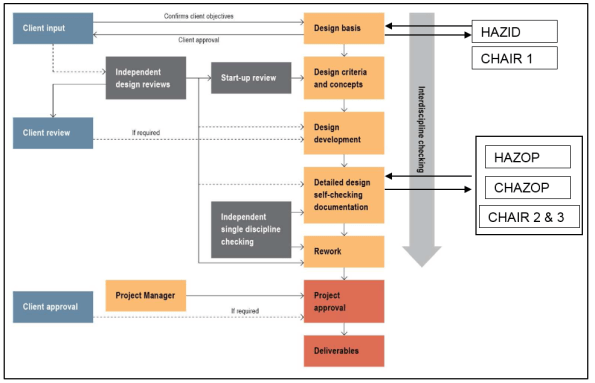
Fig 1 – The Design and SID Process
So far I have facilitated a couple of HAZOP and CHAIR meetings already and taken part into a few more. Some of the issues I have picked up so far include:
- The importance of the leader – the lead of the workshop is a key role. They need to keep the group on track, ensure all key information is recorded and prevent discussion going down various potential rabbit holes.
- Time Management – The key to the meetings is to identify hazards not solve them. Should a point take more than the allotted ten minutes it needs to be reviewed separately.
- Time Allocation – The workshop needs to have sufficient time allowance and should be broken up if possible. Generally the sessions I have been to have lasted all day and the level of interest thus the quality of the output drops throughout the day. Sequencing to allow the high risks elements first can also assist with this, as do sugary snacks.
- Design Quality – The design needs to be of sufficient quality and detail to allow the workshop to take place, otherwise it’s a waste of everyone’s time.
- Preparation – The designs need to be sent out in ample time for everyone to review and submit comments prior to the workshop – otherwise you risk the workshop disintegrating into a design review.
- Attendance – Make sure the correct number of people are present. Too many and the discussions take too long, two few or the wrong attendance and key items could be missed.
- Variations – Often this is the first time the client has looked at the design in detail and from my experience so far they try to use the opportunity to add things to the design. As mentioned previously the purpose of these workshops is to identify potential hazards, not work out who is commercially responsible.
Port Augusta to Melbourne
Prior to Christmas I moved from the Sundrop Farm site in Port Augusta to Melbourne where I am now doing my design placement with KBR. This blog summarises the progress on site prior to my move and initial projects on the design placement.
My packages of work on site had more or less come to a close by the time I left. The lining of the lagoons and the installation of the freshwater lagoon cover were complete with only commissioning remaining. The three pump stations were all practically complete, with only snag list items remaining. Ideally I would have liked to have seen this through, but inevitably this wasn’t to be. Despite my personal work packages drawing to a close, pace on site continued to accelerate as the end of the year approached. The reason behind this were linked to a drive to get the solar tower erected prior to Christmas, which enabled JH to claim more in the final progress claim of the year. As I left the project was at the 50% complete stage.

The Solar Field – beginning to look complete
With this increase in pace I ended up picking a few packages, these included: getting the tower crane foundations in place, ensuring the solar tower foundation was prepared for the first tower section, installing the pipe rack and getting the foundations in for all the mechanical plant. Everything fell into place eventually but needless to say there was a lot of coordination required, as all these activities were on the critical path and in the same 50m². The whole solar energy system is a bit of a nightmare to be honest. The primary subcontractor involved was Aalbrog Concentred Solar Power (AAL), who were on a supply only contract. The package had been tendered as a concept design and as construction progressed it was clear the level of detail in the design was poor. There were numerous design changes after the construction had begun and as I left there were still too many unknowns for JH to put out the mechanical package to tender and expect to get a reasonable price back. In the end they made the call to use a JH workforce and run the package themselves. As I was leaving the estimate was that the mechanical installation package would be at least $3million over budget. The reason for this were various, but main errors include missing the cost for the heat shield on top of the tower out of the initial budget and budgeting only $6000 for the tower fit out, when it is actually costing almost $1 million. The reasons for these omissions are again various but a lack of knowledge about the concept design and assumptions about the AAL scope of work appear to be the main causes.
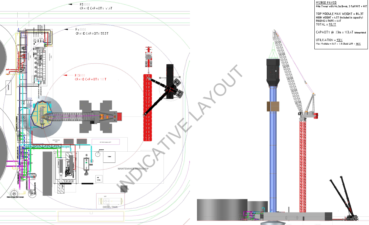
Anyway the solar tower was erected prior to Christmas as planned and now they are waiting for the top module to be finished so that it can be lifted on top. Off the top of my head it is costing $100,000 a day for the crane to be stood there!

Solar Tower – Top module still to go.
Design Phase
I have been in the design office for two weeks now. Work wise it has been a little slow, as KBR where not expecting me and there are a number of packages of work that are out at tender with the results due this week. I am based in the water group in the KBR office in Melbourne. Most of the work the group does falls under what is known as the Joint Venture (JV) with John Holland and is for Melbourne Water. All of the projects are design and construct. So far I have found myself working on the following:
- An Odour Treatment Facility (OTF) at the entrance to one of the main waste water treatment sites in Melbourne. The design of the facility is just getting to the detailed phase and I have been involved with the HAZOP process. The concept is pretty simple, foul air is drawn out of the sewer and though a filter which contains a bio media which feeds on the volatile organic compounds (VOCs), ammonia, hydrogen sulphide (H2S) and sulphur compounds, thus removing the odour. The budget for the whole project is $7.3 million.
- The second is a project is a Sodium Hypochlorite (NaClO) dosing system at the Greenvale Reservoir. The site currently uses chlorine gas but residential encroachment in the area and with additional water demands this is now deemed to be insufficient. The total project budget is $3.5 million. So far I have been involved with reviewing the P&IDs, conducting some pump calculations and am now beginning to write specifications for the associated instrumentation and plant. I am also leading with the design of the HVAC design for the new building that will house the dosing system.
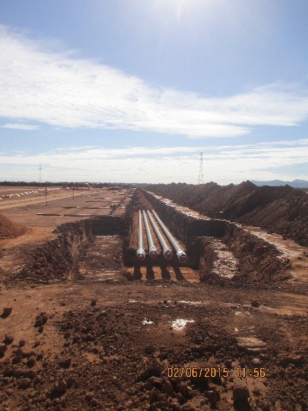
- The third project I have only just begun working on today. It involves writing the technical specification for a waste water treatment facility that is treating the leachate from a landfill site. Previously this was stored on site and driven away by tankers. The operators want to reduce cost by treating on site before feeding into the sewer system. The earth works and main pipeline are now complete and KBR are going to put the mechanical and electrical install out to tender. The idea is that the technical specification will form part of the tender pack.


Sundrop Farms Update
The head contract at Sundrop Farms splits the project into five (5) Separable Portions (SP’s). The table below is taken directly from the contract, with no further description offered in the document.
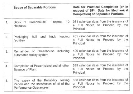
Not long after construction began on site it has become apparent that there was a discrepancy between what John Holland (JH) and the client, Sundrop Farms, believed this date actually meant. JH have always gone down the line that this is the date from which Sundrop Farm will have access to two of the greenhouses (10 hectares total). After which the client will begin their fit out of the greenhouses, which includes approximately eleven weeks of activity per greenhouse. Sundrop Farms believe that this date represented the date in which the two greenhouses would become operational, i.e. they could begin planting.
Site Progress
Eventually it was agreed that the JH proposal would be used. There was no further information stated in the contract for the client to point to and as the balance of plant is included under SP 4, the greenhouses could not be operational as it would have no heating (although this is not currently required). However JH have allowed Sundrop Farms access to the greenhouses early to begin the fit out in a beneficial occupancy agreement and a variation order has been issued to provide heating early (I plan on doing a TMR on how this is going to be achieved).
As JH and the client look towards completion, preparation activity for the operation of the plant is now beginning to build up. There are now commissioning managers both for JH and the client on site and a commissioning plan is taking shape. In addition the client has engaged a public relations company to publicise the project. As a result there have been a number of press visits to site, including the BBC. The competition is not hanging around either, Sundrop Farms has a ten year contract with one of Australia’s largest supermarket chains. Another large Australian supermarket this month launched a new brand of tomatoes called Sundrops, not everyone is convinced this is a coincidence.

Sundrop Tomatoes
Site wise progress continues at a quick pace. I have been running with the installation of three pump stations, the lining of the lagoons, pipe racks and now the installation of the solar tower, as well as coordinating the delivery of the mechanical equipment on site. JH have come to the conclusion that the two civil engineers on site won’t be able to absorb my work load and have had to recruit a mechanical engineer, so I guess I must have been doing something right.
With the summer months now upon us complaints from the subcontractors have switched from water logged roads to snakes, dust and heat. The temperature has steadily been rising, especially so inside the greenhouses. As a result the client and the subcontractor constructing the greenhouses agreed on a solution. They organised and paid for the roofs to be painted with a temporary chalk based paint, by helicopter. Not an easy task and I’m not sure how JH escaped picking up any of the cost. It would have been interesting to capture some before and after data to see how effective this is, but unfortunately no one took any before readings! Although last week Port Augusta was the hottest place in Australia, with temperatures exceeding 45 deg. Inside the greenhouses where workers are currently installing netting and grow wires in the eaves, the temperature apparently hit 58 deg, this was with the paint in place.
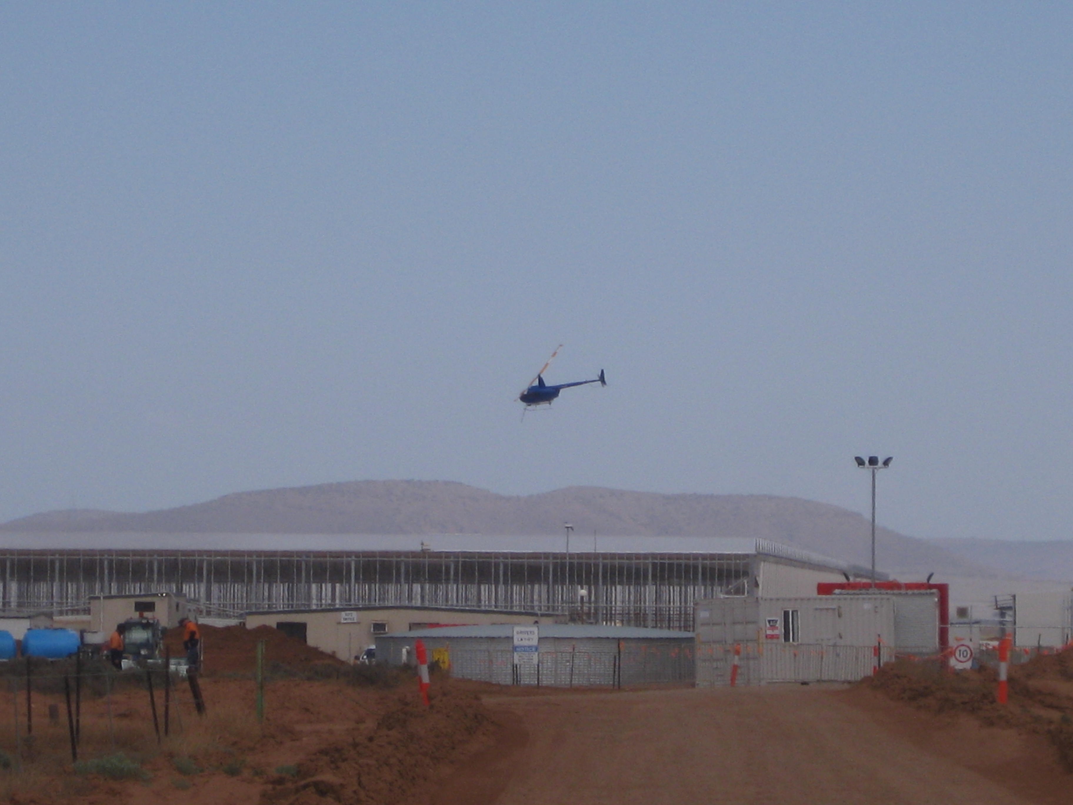
Helicopter Spraying the Roof
Sundrop Farms HV Design and Installation
The installation of the high voltage (HV) system for the Sundrop Site began earlier this month. This blog aims to give an insight into the design and some of the issues that have arisen so far with the installation. The electrical design for the Sundrop Farm project was initially done by KBR, then handed over to CNF & Associates. The onsite installation of all electrical items on site is subcontracted to Broadspectrum. On site John Holland (JH) have got an electrical supervisor come engineer who monitors the subcontractor.
Design
The HV design is based on a ring main with the 33kV coming in via overhead lines to the main switch board kiosk, which then feeds six transformers that are positioned around the site via a network of underground cables. Each of the four greenhouses has its own transformer, as well as the balance of plant area and a separate one for the generator/turbine. In addition to the mains supply the site also has a 1.5MWe steam generator and equivalent sized standby diesel generator. These generators supply 415V to a 33kV step up transformer to reticulate the generator output back into the site HV system. The steam generator can only operate in parallel to the mains power, operating as a base load generator and will not operate when the standby generator is in operation. The diesel generator can only operate when the mains supply is disconnected and will only supply the critical loads to site, 1.5MVA. Critical loads on site are based on ensuring the crop is not damaged on site. These comprise of 100% operational irrigation system, 50% operational cooling system and 100% operational heating system.

Sundrop Farm HV Design – If anybody wants a clearer copy of the image please ask.
Harmonics
The majority of the loads on site come from rotating machinery, primarily from 1152 motors that are used to circulate air around the greenhouses. Because these loads are non-linear they have the potential to generate significant harmonics. For the civil’s out there harmonics are bad they have the potential to increase the current in the system, causing increased heating in equipment and conductors, shortening machines life and increasing running costs. In addition limits are generally set by Utilities Company on the amount Total Harmonic Distortion (THD) a consumer can have, in this instance it is 1.67% allowable. The estimated value for Sundrop Farms exceeded the value set by the utility company, South Australia Power Networks (SAPN).
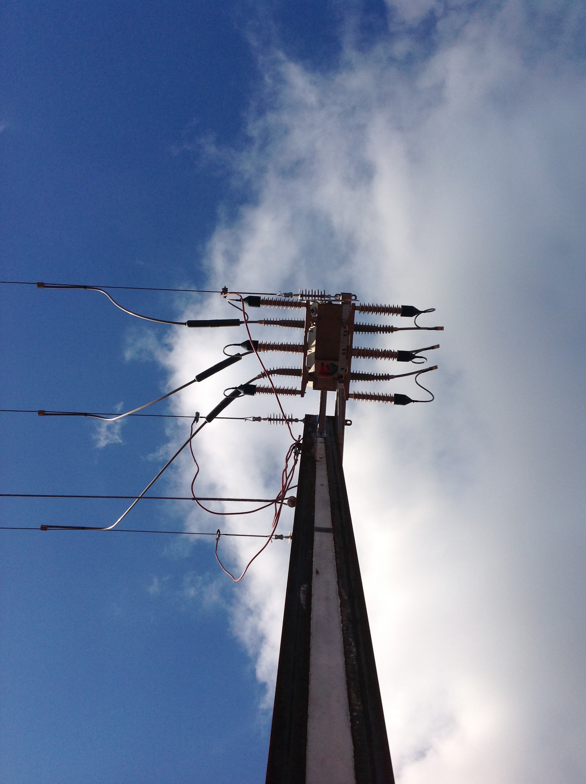
Pole Mounted Switch above the 33kV Kiosk
To reduce this value the designers had a number of options, rectifiers, harmonic filters or pulse width modulators. All of which have significant cost implications, for the site this was estimated to be around $500k. However SAPN failed to meet the date which they were due to supply power to the site by. They failed to get the necessary permission to erect the HV line across a recognized heritage area, thus their installation was delayed. With this leverage and through negotiation with SAPN, JH were able to move the point of common coupling which is where total harmonic distortion is measured to a substation 6km away. The resistance of the circuit was increased by this additional cable length and reduced the effect of the harmonics to a limit that was acceptable to SAPN. The impact on the project of not having power to site – zero as we have yet to get the HV transformers in position.
33kV vs 11kV
Another point I picked up on early in the project was that the onsite distribution changed from 11kV to 33kV on the designs. Through a value engineering process it was identified that significant savings could be realized by removing the 33kV switchroom and the 33kV to 11kv transformer and reticulate power around the site at 33kV, this design change saved approximately $800k. Other savings realized by this change included being able to use smaller cables which equates to quicker installation time and cheaper purchase costs.
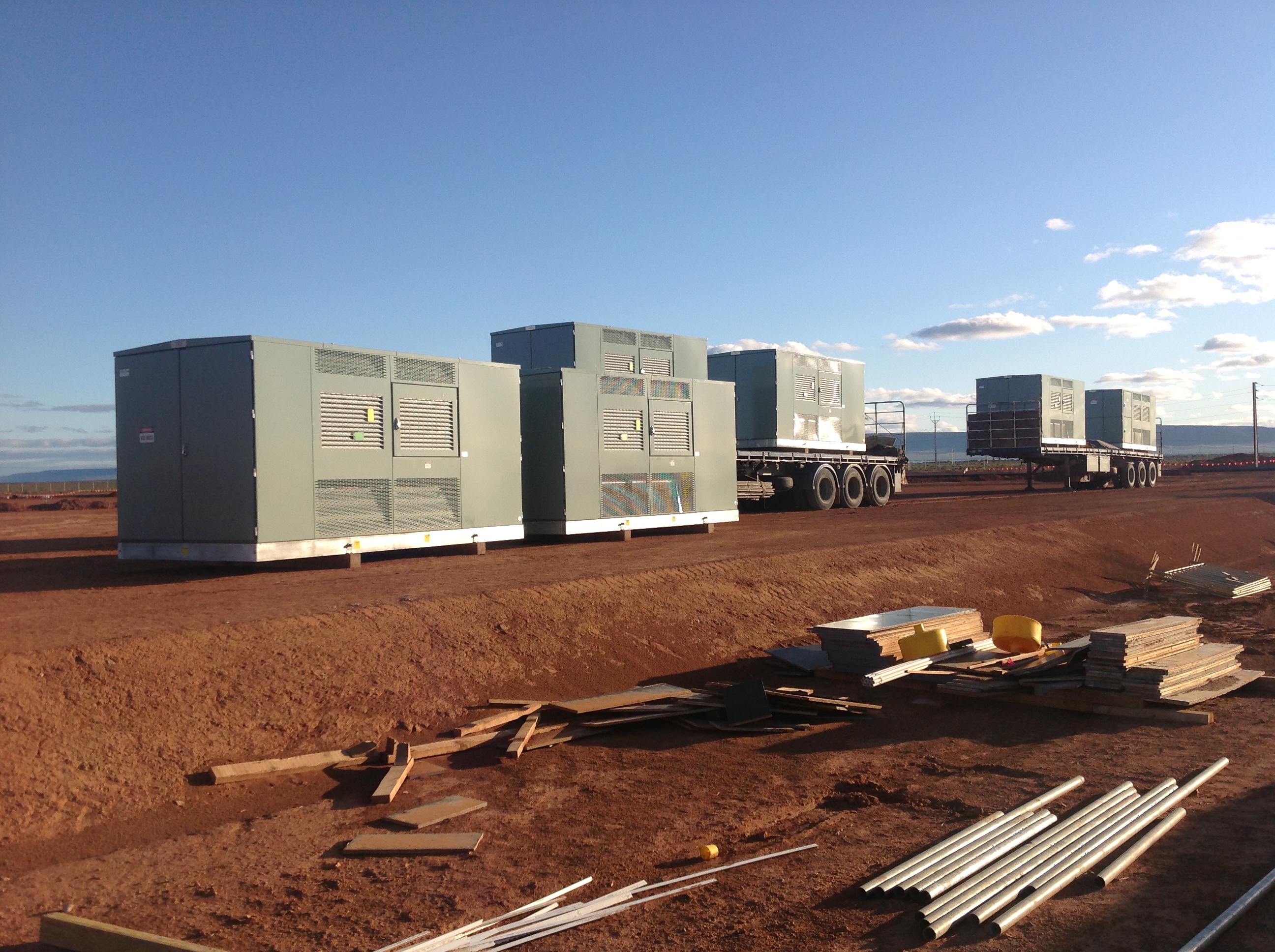
Schneider Transformers arrive on site – the unloading of these became an issue when it was identified that they weighed 12t, not the 9t on the drawings!
Installation
The design called for the cables to be direct laid. However when the installation contractor began to develop their program it quickly became apparent that this wouldn’t work on site. The way the cable was routed and the fact that the cable was coming off the same drum meant that the trench would have been open for up to three weeks. This would have resulted in severe access issues across the site and opened JH up to multiple claims from other subcontractors. The solution was to install conduit in the majority of the areas across the site and then pull the cable. The actual cost of switching was between the two was seen as cost neutral. Laying conduit involves more work but it means that the plant used for the installation can be off site much quicker. In addition JH were able to supply the majority of the conduit free of charge, as we had surplus on site from a previous project.
The cable pulls themselves required some detail planning, the longest was 370m long. The cable was pulled using a trailer mounted winch which was in turn connected to a Ute. Even with the weight of the Ute, lubrication in the conduit and rollers the friction encountered during the pulls was such that a second Ute had to be attached to the first to stop it moving.
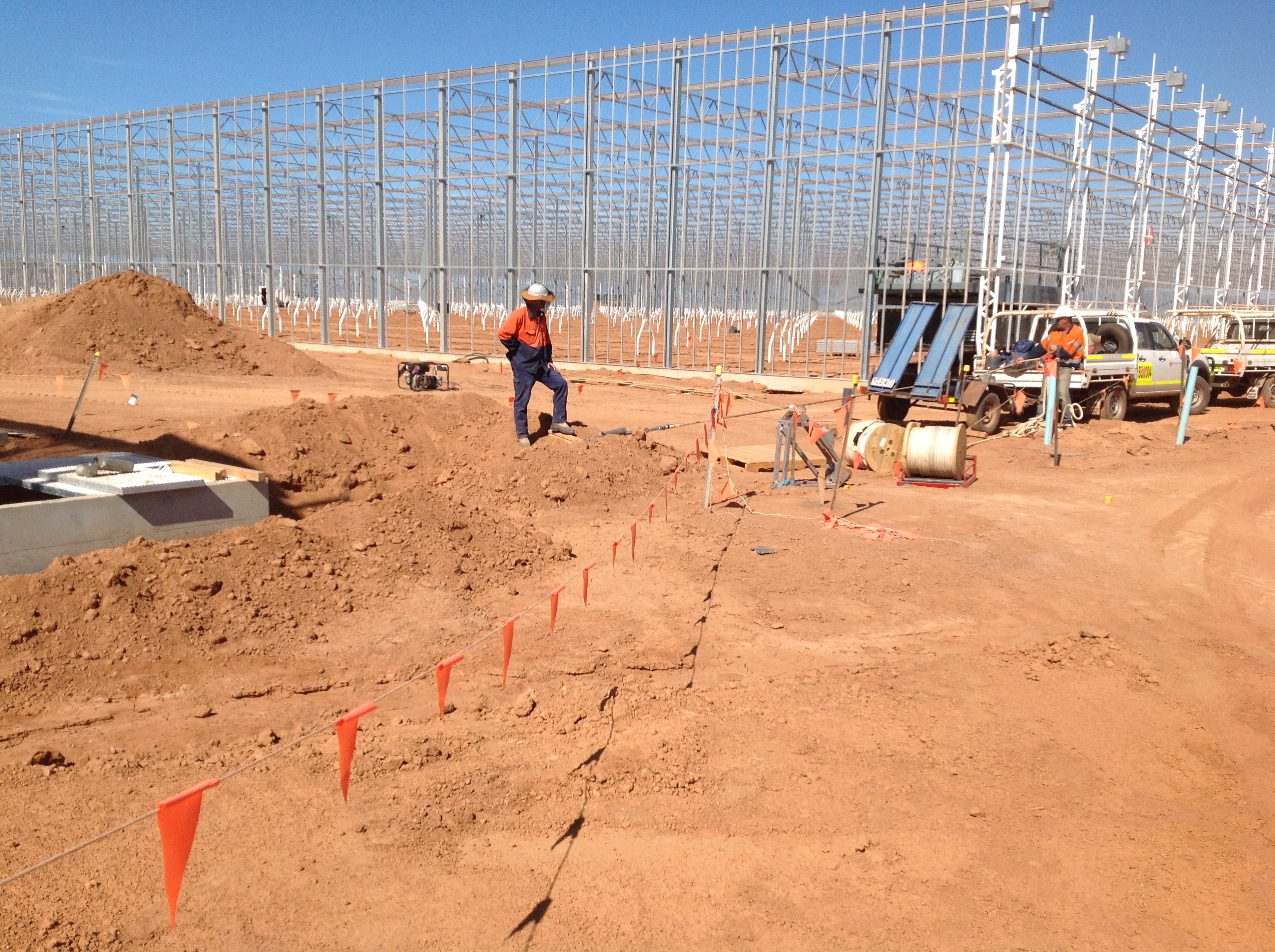
A poor image of one of the cable pulls taking place.
Other issues encountered so far on site have arisen from the transformers and kiosks supplied by Schneider. The original HV cable in the design was supposed to be three single core cables, however this was switched to a single three core cable, to reduce costs (this was free issued by JH, again surplus from a previous project). However this change was not communicated to Schneider, and as a result none of the cables now fit in to the transformers gland plates because the larger diameter three core cable has a bigger bend radius. The solution to this problem is still in discussion. The current plan is to terminate the cables prior to the transformers getting lifted into position and install new gland plates on site. Not necessarily a big job, but as with everything electrical to get it done to the correct standard will be costly.
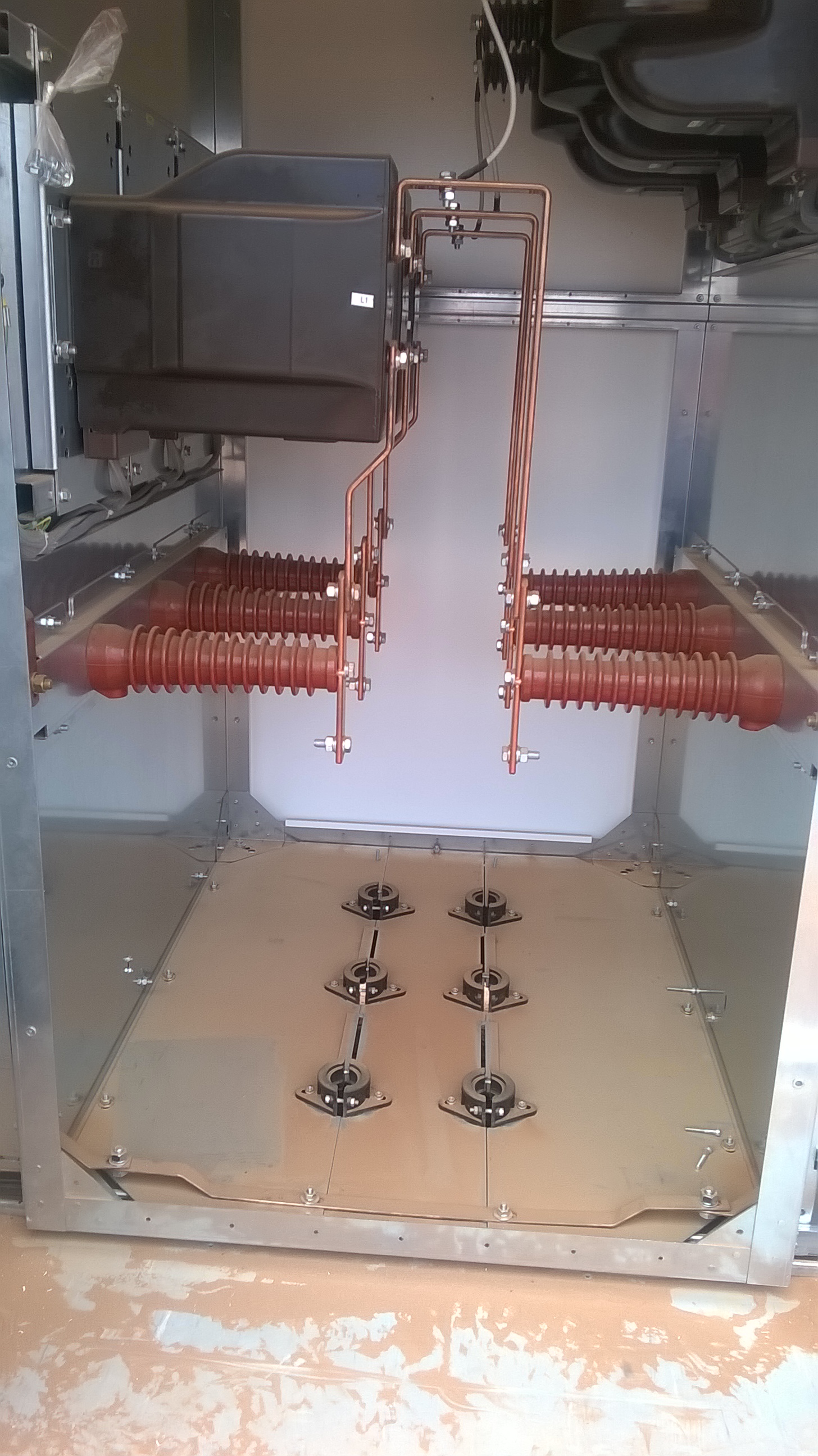
The Gland plates in the current transformers – perfect for three single core cables, not so good for a single three core cable.
One of the positive aspects of the installation is that the subcontractor we are using. Broadspectrum are engaged by JH to do the HV and also by our subcontractors VDH and Aalborg who are responsible for the greenhouses and solar energy system respectively. Although this was not planned it does mean that a lot of the potential issues between the various scopes of work, in terms of gaps and interconnectivity have been elevated. Also as the subcontractors are both form overseas it ensures the work carried out is to Australian Standards.
GRP Pipe Design
Design
The remainder of the GRP pipe line was installed by York Civil, using GRP with flexible coupling free issued by John Holland. The design showed that the pipeline would transition from a flexible pipe (i.e. the use of couplers and concrete thrust blocks) to a rigid pipe (i.e. fully welded) at the interface between GO scope of works. Originally GO were to supply all of their own GRP for the reminder of the underground and the above ground piping that leads to the pumps. However our procurement spotted a potential opportunity and decided to use the surplus GRP we had onsite to free issue to GO instead. This all happened during the tender stage, about three months ago.
Flexible GRP Pipe Installation.
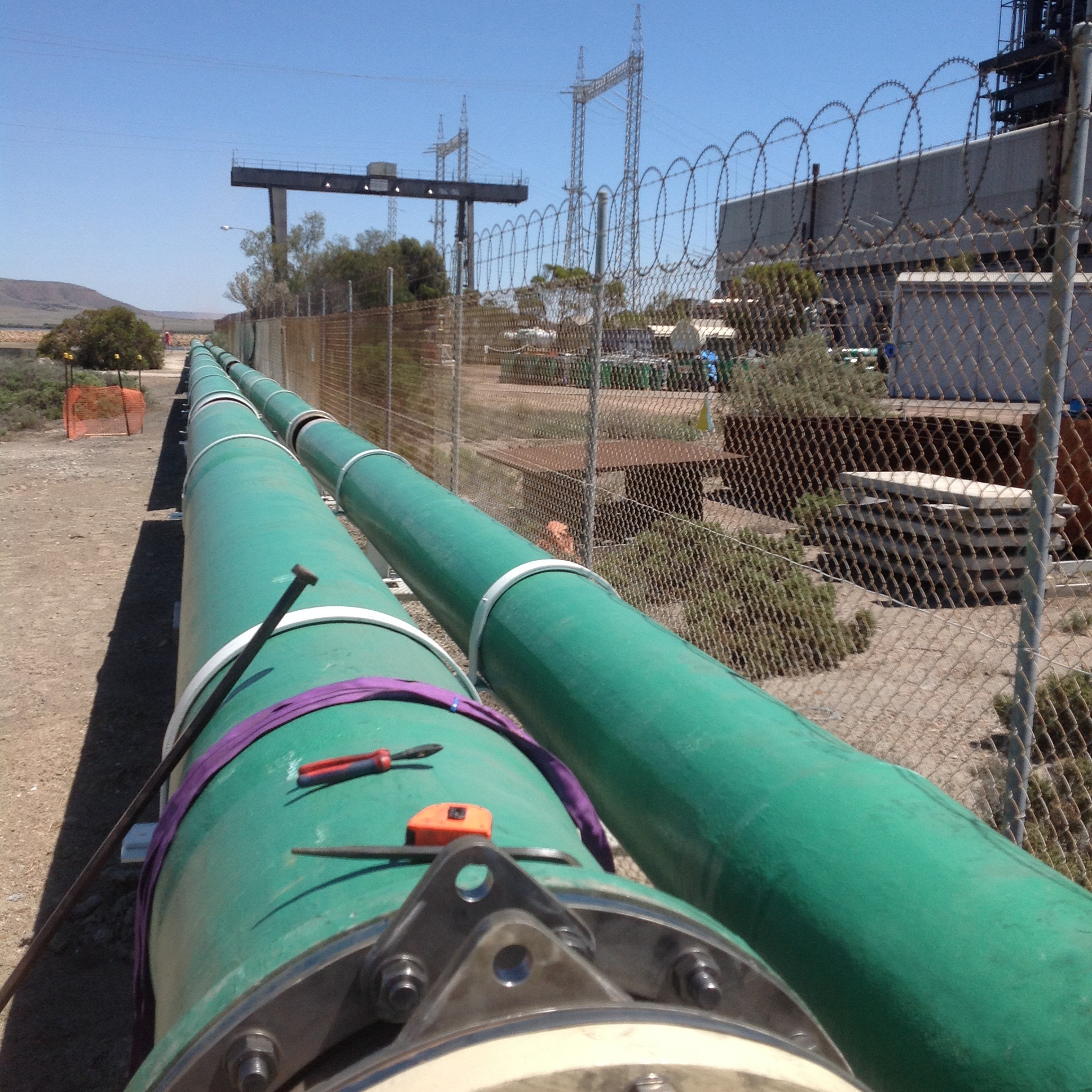
Above Ground Rigid Pipe
Issue 1
After arriving on site GO began some other packages of work and provided spool drawings for the GRP they were supplying for approval. During the design of this GRP the manufactures passed the design to a consultant for ratification. The consultant identified significant issues with the longitudinal strength of the pipe, which had been designed using the specification supplied by our designers (KBR). After this several discussions ensued on site between myself and GO, it became apparent that we had become messengers between the two technical experts (one in KBR and the other in the consultants) who had differing opinions. Eventually I was able to arrange for them to get in the same room and thrash the problem out. The final outcome was that the pipe needed to be upgrade at a cost of $45,000 to deal with the additional longitudinal strength. These longitudinal forces were due to the operation of the pumps and thermal expansion. KBR were able to argue the fact that there was enough information on the drawings for subcontractor to know this and even though GO were on a supply and install contract they had a duty to do some design. Luckily in the same meeting KBR were able to muddy the waters to such an extent over who was responsible for these changes that GO accepted the cost, rather than try and challenge it.
Issue 2
About a week after the above issue was resolved I received a separate email from KBR asking that I check the GRP we were free issuing to GO as there may also be issues with that. After speaking to the GRP supplier it became clear that the pipe would not be suitable for the current design. The design was then changed to switch the section of pipeline back to a flexible. With John Holland receiving a bill for the redesign and a $20,000 variation from GO, with further changes to the design expected this will rise. My role on site has been to manage this process and try to ensure design changes have minimal impact on the work already completed. The cause of this issue could easily be passed back to the procurement team for not checking the pipe would be suitable, however I think it goes deeper than that. The designers were aware of the plan to use the GRP but didn’t comment until GO raised the issue above. In addition the suppliers of the pipe had previously agreed it would be suitable without actually understanding the full design. Unfortunately it looks like cost of all these variations is likely to come to John Holland. Although I have already been tasked with trying to pin this on the designers.
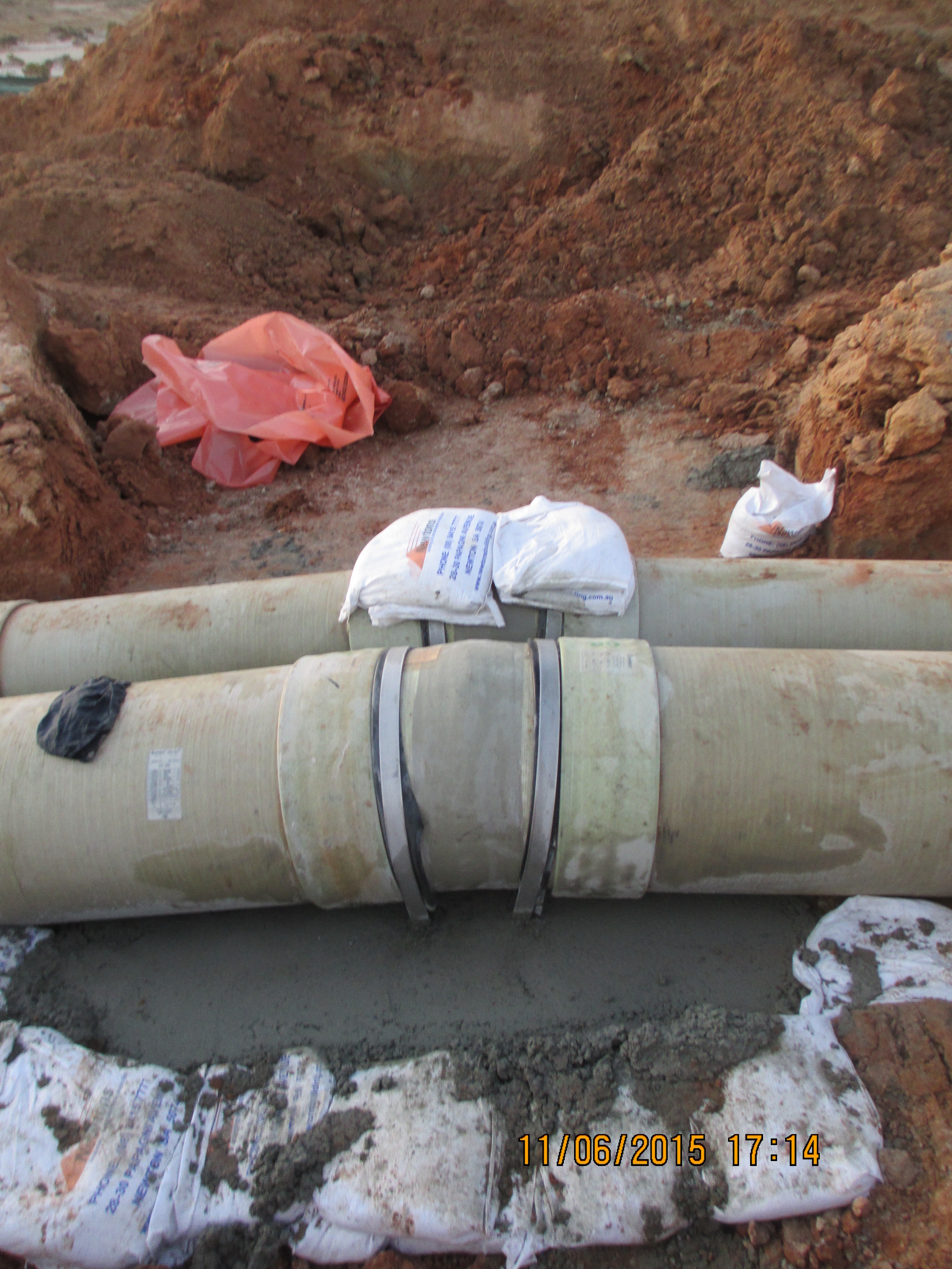
Issue 3
The more worrying issue was the fact that the same free issued GRP was used at the other end of the pipeline where it discharges into the lagoon. The pipe was wrapped to make it rigid, as shown on the drawing and using the wrapping methodology provided by the pipe supplier. Once installed the pipe was hydrostatically tested to 625kPa, a value given by the designers in answer to an RFI just a week earlier. Two days after conducting the test we received a further email from KBR requesting that we not test the pipe as it would fail under the pressure. Luckily the test went fine but the potential for injury was there and as such this has been raised as an incident within the John Holland system. Operationally the designers see no issues with the pipe as it currently is. The pipe is positioned 5km away from the pumps and is open ended so the pressure is deemed to be negligible.

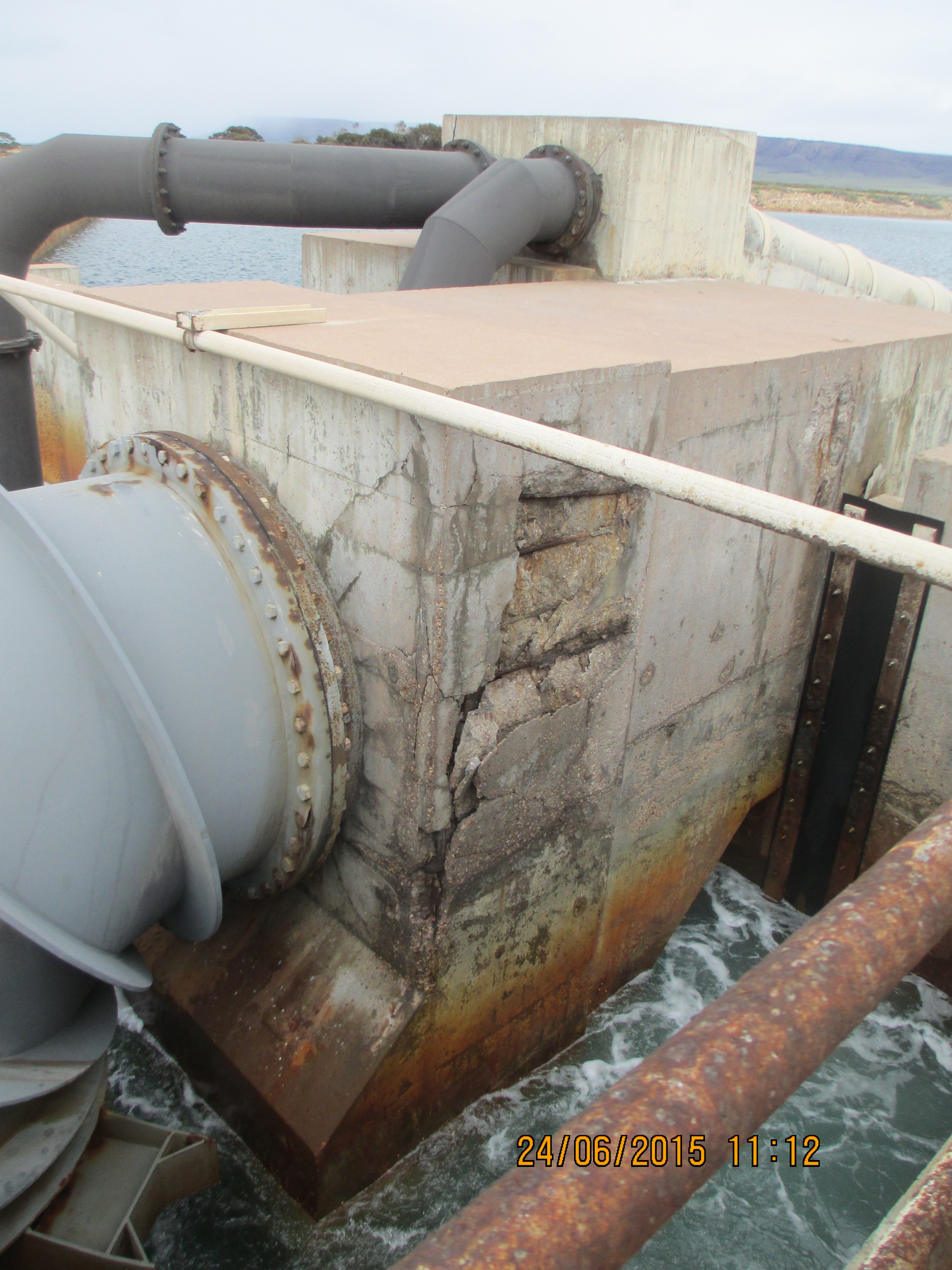
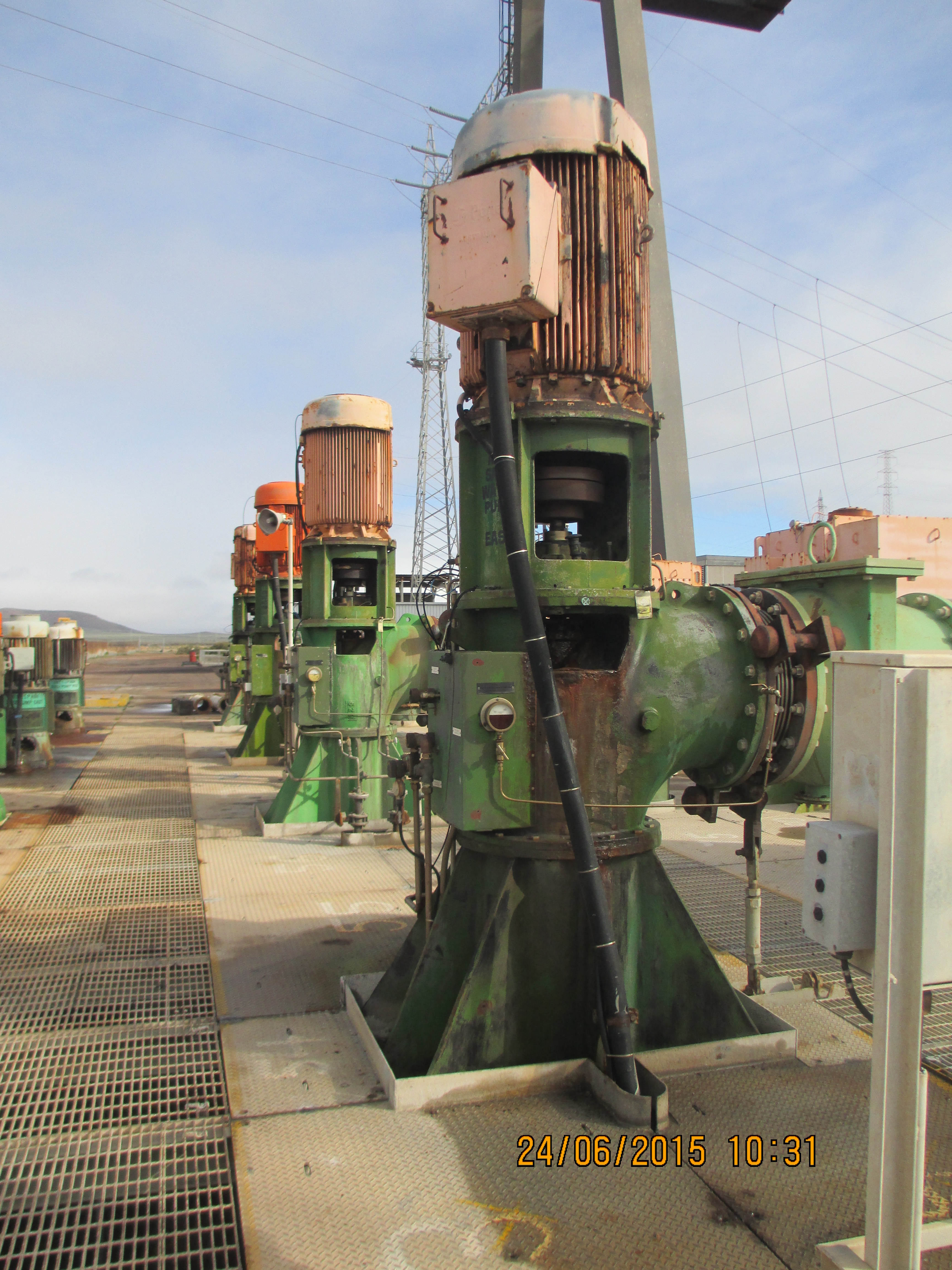
Seawater Inlet Pipe
Conclusions
The design of GRP for pipelines is a specialist area in its own right. In the case of the site at Sundrop Farm it was clear that the designers at KBR were not fully aware of what they were doing in relation to the GRP design. The design and associated documents had a number of flaws which had they been scrutinised by a specialist would have been picked up much earlier, which in turn would have reduced the financial impact of the changes we are now having to manage on site.
With regards to procuring items the supplier needs to know as much information about the environment, system and operating conditions their component will operate in. Had the GRP suppliers understood the full system and operating conditions of this design they would have been able to provide more suitable product capable of operating as designed and reducing the impact of future changes. Instead they were responding to isolated RFI’s from the procurement team, thus providing answers which were not relevant to the situation.
From a site point of view it is difficult to see how we could have responded differently. We were provided with IFC drawings from the designers and pipe procured by our procurement team. The designs go through a review process both by the designers and John Holland. Had it not been for the subcontractor conducting a review of the GRP and us responding to the information they provided the installation would have continued as per the design. The impact of this is hard to quantify, the plant could have operated as designed for years or the GRP could have failed as soon as the plant was switched on.
In other news
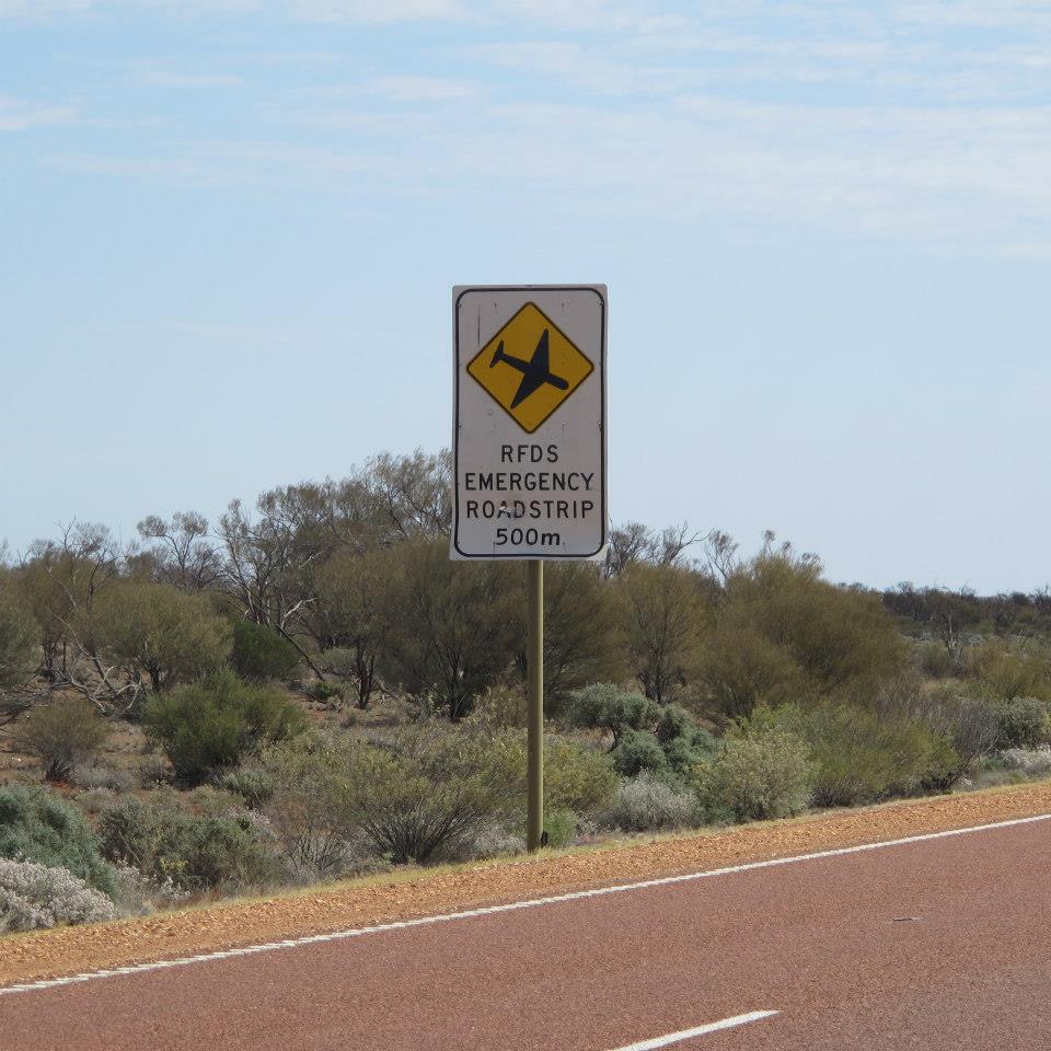
I took a long weekend off earlier this month and took the opportunity to drive up to Uluru or Ayers Rock. The drive takes about 12 hours through the outback and is broken up with nothing apart from a missile testing range, the odd service station and Coober Pedy. To break up the journey we stopped at all of these and spent the night at Coober Pedy. The town’s main claim to fame was the discovery of opals in 1915. Troops returning from the First World War began to settle in the area from this date. Because of the harsh climatic conditions the settlers began to tunnel into the rock and build homes (called dug outs) underground.

Wilfred Pointing to His Christmas Present
Today the town has a population of almost 1700 and most of the towns building remain underground. The hotel we stayed in the temperature remained between 22 and 25 degrees all year round without the need for air conditioning, despite outside temperatures exceeding 40 degrees for much of the year. Natural ventilation is provided by a number of shafts that extend from each of room to the surface above. Each room had an umbrella positioned upside down under the shaft in the corner to catch dust landing on the floor. The wiring throughout the hotel was done by drilling horizontally, then using a vacuum to suck a piece of tissue with a piece of cotton attached and then pulling the cables through.
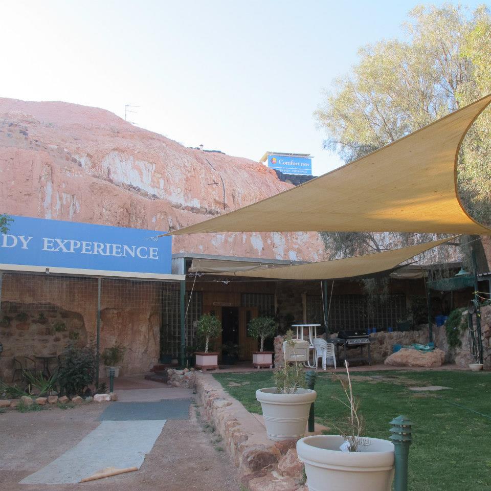
The Comfort Hotel Coober Pedy
The Seven P’s.
In should come as no shock to anybody that water in is pretty expensive in South Australia, costing in the region of $3.32 per kl. The project received its first bill this month (don’t ask me why it has taken this long to get here) that covered the start of the project Dec – Apr which was quickly followed by a second covering May – Jul, with the total over $350,000. The cost arose from the fact that water was required almost 24hrs during the summer months for dust suppression during the bulk earth works. Surprisingly this cost was not captured in the budget for the project and was excluded from contract with the subcontractor responsible for the earth works, so it will eat in to the profit for the job.
From this episode the project team were tasked with carrying out a review of the budget to identify any other holes and quite a few were identified. The main one sticks with the water theme as it became apparent that the cost of filling the various systems on the site (in the region of 30Ml) with demineralised water had not been accounted for. The options for supplying this were limited, using the reverse osmosis plant at the local power station or getting in portable reverse osmosis plant to site to produce our own. The power station was discounted because in order to fill the tanks on site we would need to fill the 5km worth of pipe to get it here and find a method of pumping it. The current plan is to use a subcontractor to bring in temporary plant to produce it on site. This is producing a number of issues in itself, the main one is trying to find a subcontractor with the capability to do this, we are currently looking at GE supplying the equipment and another subcontractor to install and operate. Further issues we will need to work out on site include finding space for the plant, power and water to operate the plant and a method of discharging the brine, all of which the project will have in the future but not necessarily in time.
No one is sure what this is going to cost but best estimates coming from our procurement team at the moment are around $500,000, plus the cost of the feedwater approximately $100,000. This is likely to fall to John Holland, as the head contractor we are ultimately responsible for commissioning the plant (although no doubt we will try and push some of the cost back to the client).
Looking for causes as to how this could have been missed I think it’s quite simple, in the rush to get shovels into the ground after signing the contract a draft program was produced, with no product or work breakdown conducted to back it up. As the project progressed no one has had the time revisit the program so it has just been updated where necessary, which is fine for sequencing works, but doesn’t identify items that are missing altogether. In their defence I know at the time the project team was pretty limited and they were under immense pressure to get the project started.
The picture below is just to attract some attention to this blog, it shows the planned lifting strategy for the 115m high tower, hopefully before I leave site in November.
Sundrop Farms Project Update
This blog aims to provide an update on site progress, as well as demonstrating the wide range of tasks that seem to land on your lap as an engineer. Apologies if it is a bit long, not had a lot of time recently to blog.
My main area of responsibility (the pipeline) is nearing completion, with the filling for the hydrostatic testing taking place as I type, should take around 3.8 days. My involvement in this has been limited to developing the test procedure alongside the subcontractor and client, as well as ensuring the relevant standards are followed and John Holland isolation procedures are adhered to. It did however give me the opportunity to wheel out some P=ƿgh action when the client asked why we were not going up to the full test pressure (answer – because the pressure gauges are not at the lowest point). Other areas I have recently taken on include the intake and outflow at both the sea and project end, as well as the lining of the lagoon structures and all the associated pipework.
The intake and outflow for the pipeline at the sea end is a $1m package of work which has recently been awarded to Guidera O’Connor. I have been responsible for developing the scope of works, getting the designs to IFC stage, introducing the subcontractor to the project and on boarding their construction team. The design currently ties in with existing infrastructure at Alinta power station. A few weeks ago the power station announced its closure in 2016; previously this was due to be in 2030. This clearly has some major impacts on our project:
- Firstly the site is to be returned to the condition it was prior to the power station, including the inlet channel that we are building on and the control rooms that we were going to use for power. Currently this has been passed back to the Client to come up with a solution through negotiations with the land owner.
- Secondly the Environmental Protection Authority sign off for the brine discharge from our site was based on the outflow of the power station for diluting and mixing, prior to the water entering the sea. Further models are now in development by the University of New South Wales to analyse the impact.
A potential positive is the fact that the government is under pressure to do something about the number of unemployed persons in the area and as a result there are already discussions for a second Sundrop Farm project in the area, clearly this will be dependent on the commercial success of this one. At the moment we have been to soldier on with the current designs, with the hope that the Client comes through in the end otherwise we will have some major variations coming our way. I have included some photos of the existing infra structure firstly to show the state of disrepair that we are expected to link into and secondly to balance the fact that the remainder of this blog is civil based.

The contract for the lining of the ponds was awarded to Fabtech and was valued at $750,000 – at first I thought this would be a relatively pain free scope of work. After interrogating the drawings I discovered a whole can of worms in the form of buried services. Basically I have spent the last two weeks trying to find out who is responsible for what services, taking items out of various scopes of works and awarding variations to Fabtech in order to progress works as they are already onsite and we can’t afford any delays. In the process I have found gaps in both the design and procurement packages, which always makes you popular on site. One of the most surprising gaps at the moment is that there is still no plan for the waste water across the whole site, even though the subcontractor for buried services starts next week.
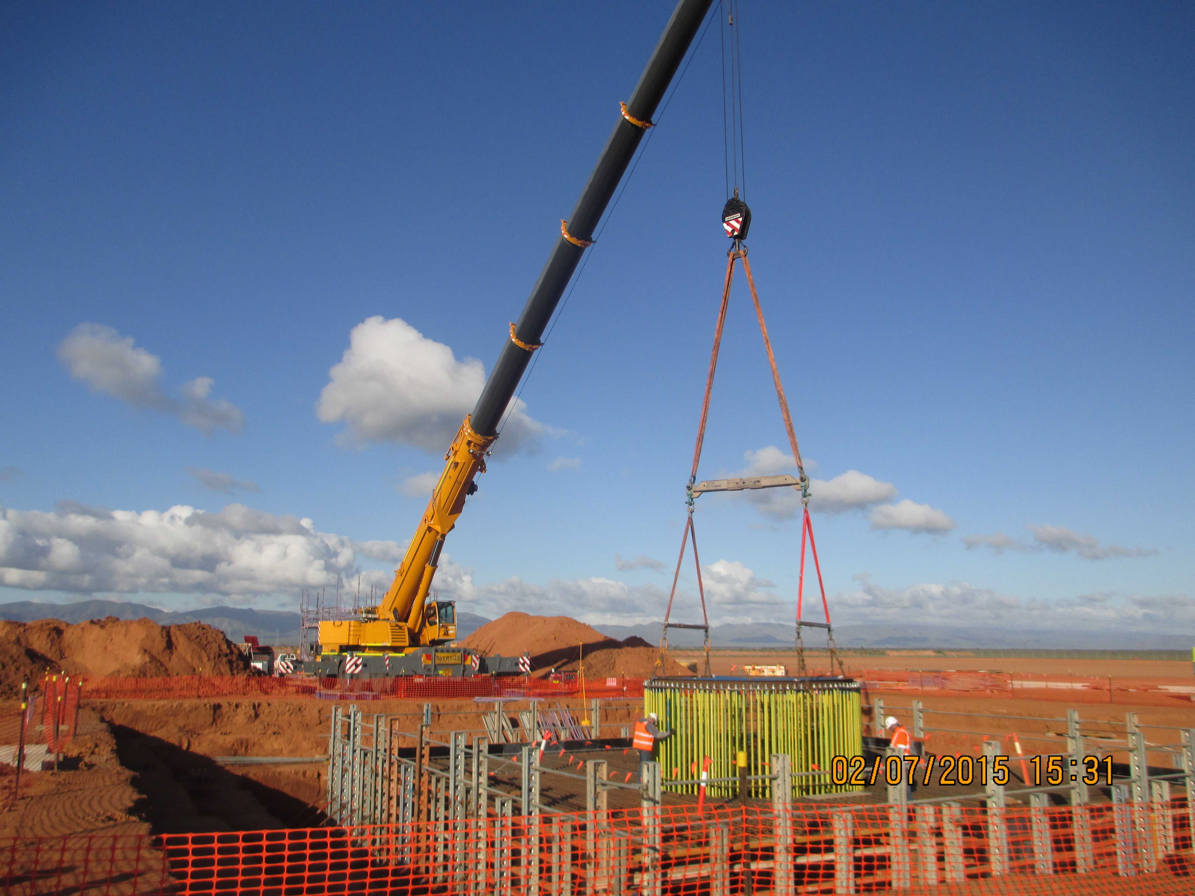
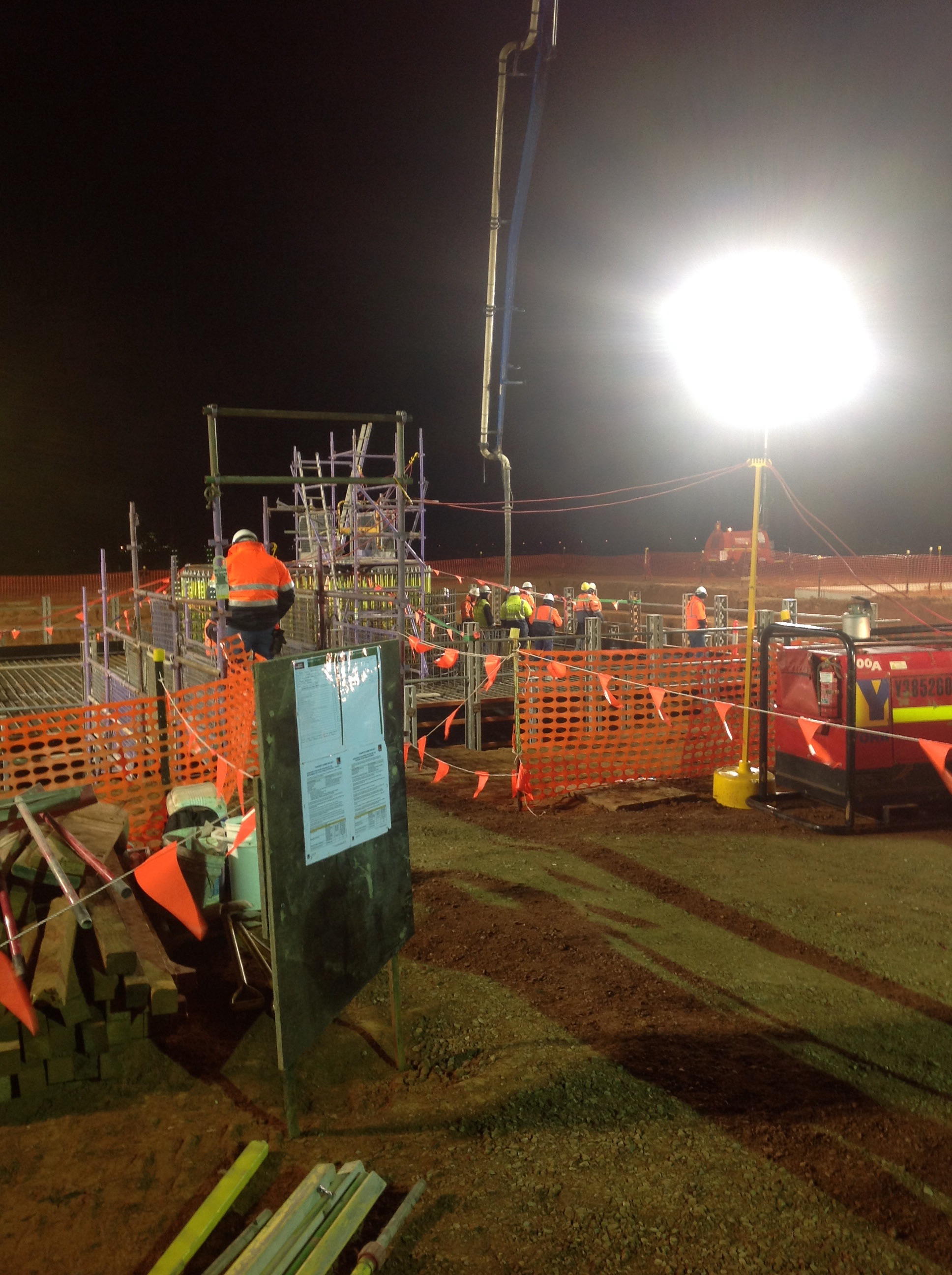
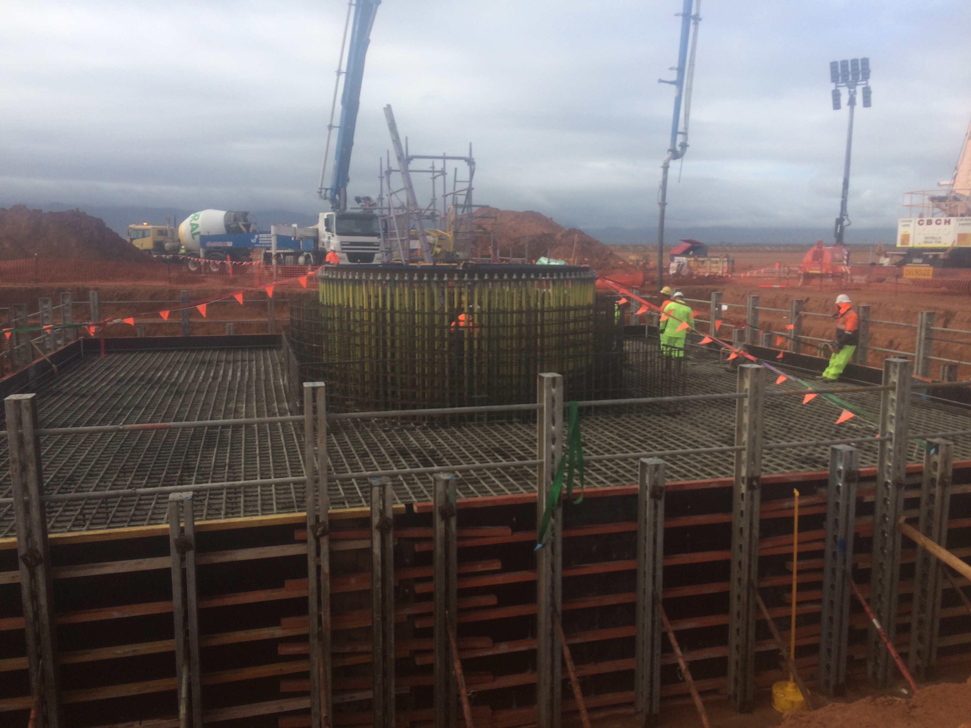
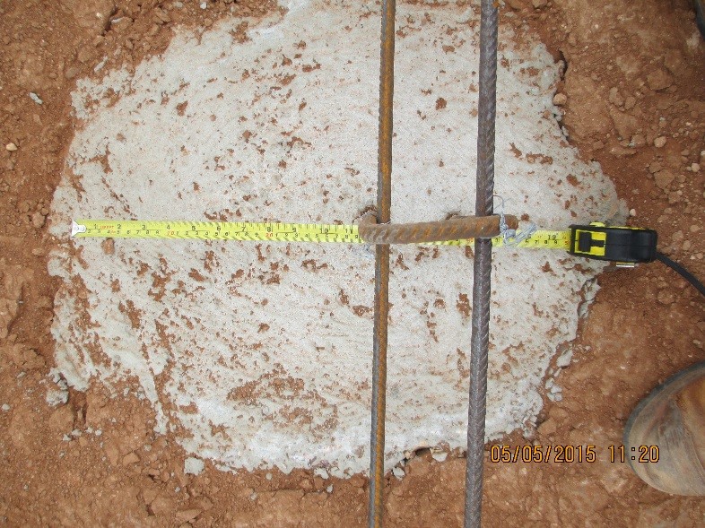
The big recent event on site was the pour of the Solar Tower foundations; I have included some pictures below for all the civil types out there. In total the pour was around 550mᵌ, it began at 0300hrs and lasted until 2000hrs. The planning and preparation involved in the whole pour was quite impressive and was greater than what I witnessed on some military operations, with standby pumps, plants and trucks identified across the state and put on reduced notice to move. Inside the reinforcement you can see the ring of 200 bolts, 4.5m long which will eventually hold the base of the tower. The photo’s below show the template holding the bolts getting lowered in to place, the start of the pour and the end of the pour (yes it is raining).
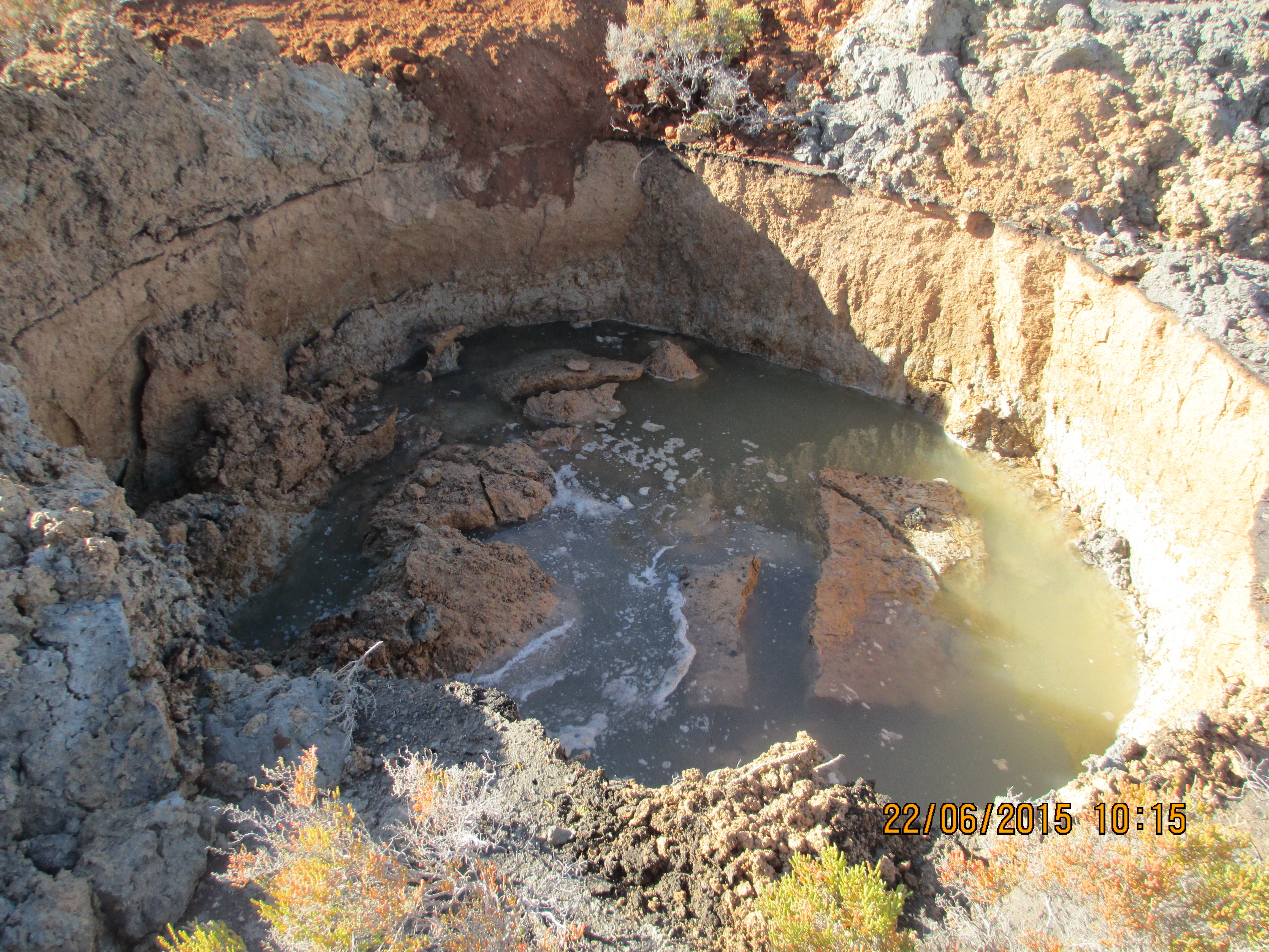
Other random things I have been running with include dealing with some asbestos that was discovered whilst excavating the pipeline writing an Acid Soil Sulphate (ASS) plan and the redesign the pipeline as it crossed through an area that locally has become known as the ‘bog’. The area in question was a concern as the pipe transitioned from an area of pale brown sand to an area of grey clayey sand before going back to sand. From John Morans lessons the mention of clay clearly sent alarm bells ringing in my head. As a result I was then tasked with organising a geotechnical investigation to try and establish an estimate of the long term settlement (which came back as 50mm over the 100m) and then amend the construction method and design to bridge the gap whilst ensuring there was enough flexibility to prevent the joints from opening up at a later date. All very civil orientated but I suppose it prepares me for future roles as a PQE in the Royal Engineers. What was a shock was the fact that this whole episode came as a surprise to everyone, despite the fact that the area can be clearly seen on Google earth. The photo below shows the result of a test pit, which started out as 1m wide by 3m deep trench about an hour before.
Sundrop Farms Update
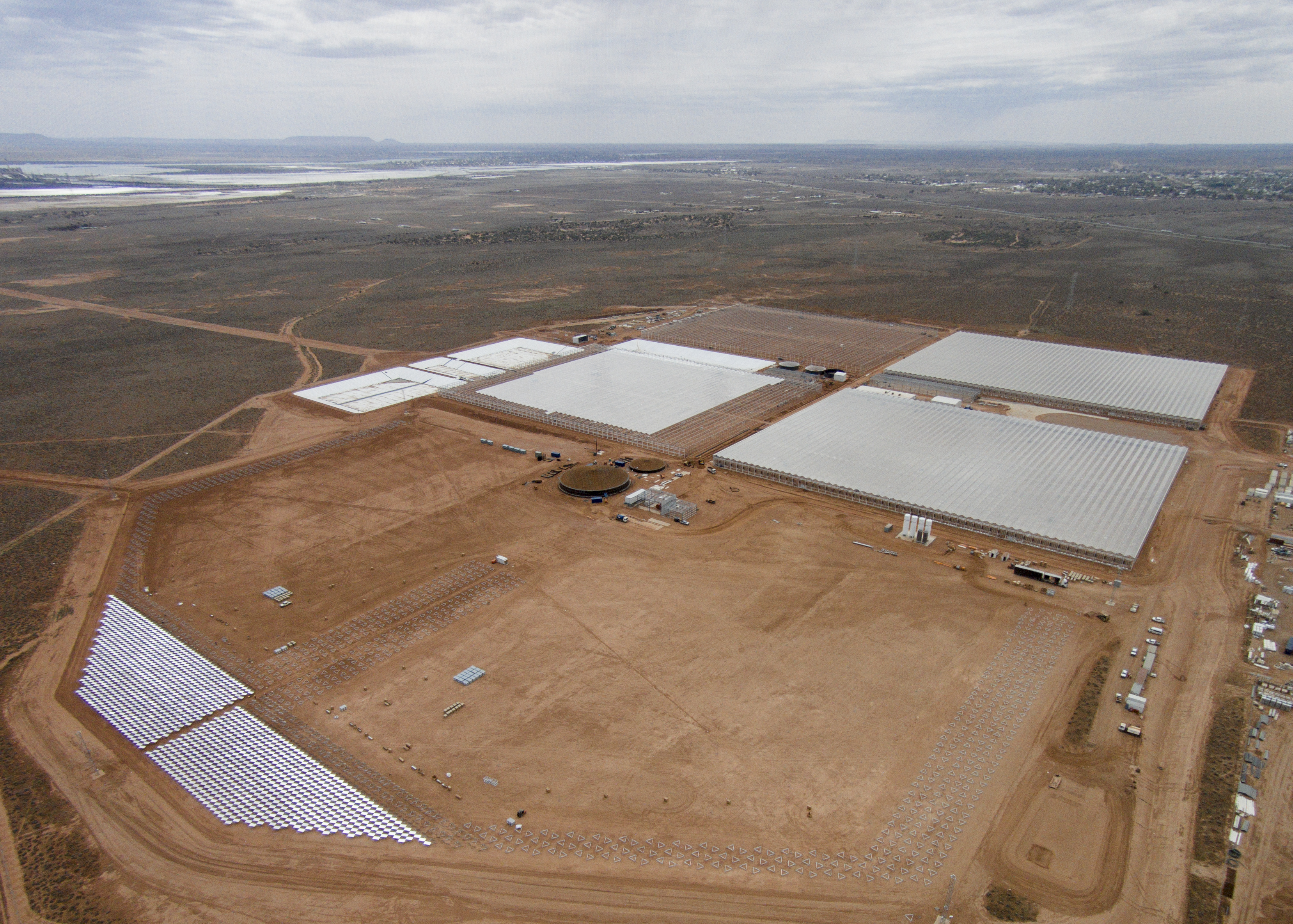
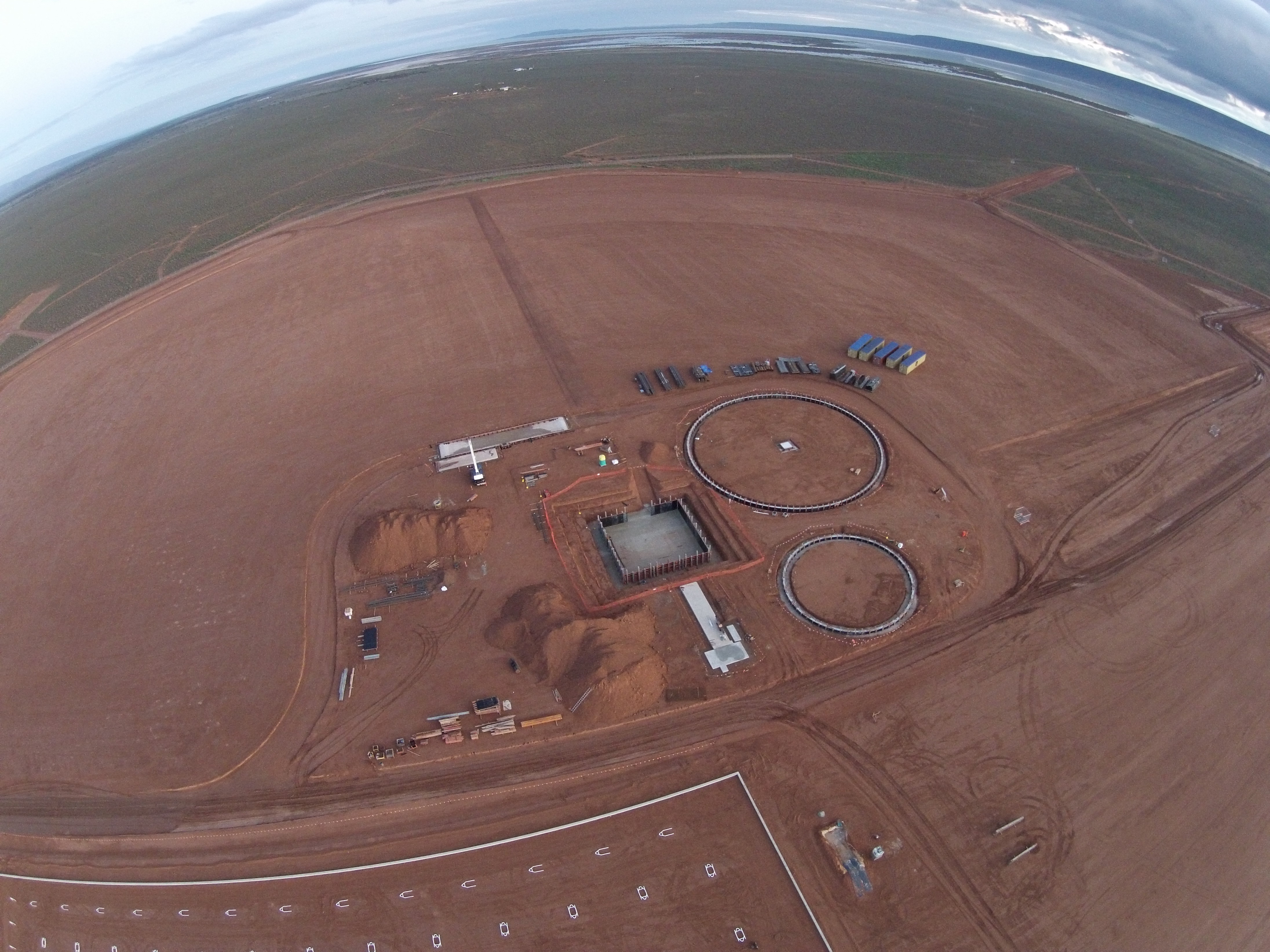
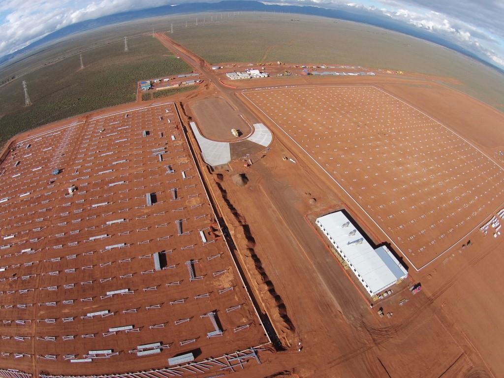
This blog aims to provide an update on the Sundrop Farms project to date and highlight a couple of issues currently experienced in site. In terms of progress the photographs below were taken by the client using a drone and summarise where the project is up to. The first photo shows the power island and some of the foundations now getting poured. The two circular foundations are for the two Thermal Energy Storage tanks, the larger has a capacity of 22000 m³ and will maintain the water at a temperature of 95 °C and the smaller has a capacity of 6000m³ and will maintain the water at 43°C. The square foundation in the centre is for the solar tower, currently we are waiting on site for 200 bolts, 4m in length that will sit within concrete for the base plate of the 115m tower to be bolted to. The tower itself is based on the design of a wind turbine tower and is getting manufactured locally. For a sense of scale you can see the 40ft iso containers positioned in the top right of the photo.
The progress on the greenhouses can be seen on the photo below. The first two greenhouses form part of Separable Portion 1, construction on the one on the left hand side of the photograph began in Apr 15 and the erection of the steel work that forms the frame of the greenhouse began last week. The amenities building is the complex to the bottom right and comprises of 16 modular buildings that have been lifted into position and fit out over the last 8 weeks. One of my responsibilities so far has been the management of the installation and the final inspection of the complex last week. Following the handover the subcontractor attempted to submit their practical completion notification certificate. On looking over their contract there was no definition of the term practical completion or mention of the certificate and what this means. The definition of completion was given, but part of the definition was the requirement to have completed the commissioning, with power, water or sewerage connections currently not in place this cannot happen. The completion of the building also marks the start of the liability period, so clearly it is within our interest to delay this for as long as possible. What I also found missing out of the contract was the completion date, which was left blank. The commercial manager on site has now taken this on and has sent them an official letter rejecting their notification of practical completion. The proposed solution is to seal the buildings up and wait until October, when it is planned that the services will be in a position to connect to, then bring them back on site to commission; with the electrical subcontract still in the tender stage I think that this is still slightly ambitious.
The biggest site wide issue at the moment is rain, we have had 39mm in the last 4 days, the average for the whole of June is 24mm. It started raining here on Sunday and has continued with varying amounts since. Access to site is via a dirt track that runs parallel to the permanent road, which can be seen at the top of the photo above. The permanent road has been completed up to the point where it needs sealing, the subcontractors are waiting for the final detail of the main junction to be confirmed prior to sealing. The access road is getting to the point where it is impassable, I had to recover a 4×4 on Monday and we have had a number of delivery trucks stuck. The situation is compounded by the fact that the toilets are reaching capacity and diesel needs refilling by Friday. The John Holland response so far has been to soldier on, leaving the decision to subcontractors to make a call on whether to work or not. The reason behind this is that the extension of time due to inclement weather clause was removed from the head contract between JH and the client, JH then passed this risk on the subcontractors by removing the clause from all of its subcontracts. Currently the Health and Safety manager and the package lead are at logger heads over this. As far as emergency access is concerned this is maintained by the fact that the permanent road could be used, in addition the risk on site is minimal as there is minimal work being conducted. Obviously if the toilets or diesel become an issue this will change the situation. The image below shows my UTE after attempting to inspect the trenches on the pipeline.

HSE and Quality Control
This blog aims to explore some of the issues associated with working with subcontractor who have little experience working for a Tier 1 contractor. It will look at a number of examples that have come to light recently on site, relating to both quality control and health and safety.
In my first blog (20 Apr 15) I mentioned the fact that one of the risks identified by John Holland (JH) was the use of subcontractors not accustomed to working with JH procedures, this has now begun to be an issue on site. The first case was highlighted in the previous blog and involved the rejection of too loads of concrete due to the lack of an adequate Inspection Test Plan (ITP). The impact of this was a two week delay on the program for the first greenhouse and it contributed to 25% wastage of concrete (the decision on who is to pay for this is still to be confirmed). The delay was caused by the failure within Van der Hoven (VDH) to agree what standard the structures were designed and constructed to and thus what tolerances had to be used. This led to numerous conflicting tolerances, some of which the construction force were unable to meet. In the end the ITP was developed by JH and given to them in order to progress works.
Pillar Foundation – Yes the hair pin is supposed to be in the centre
Wall Foundations
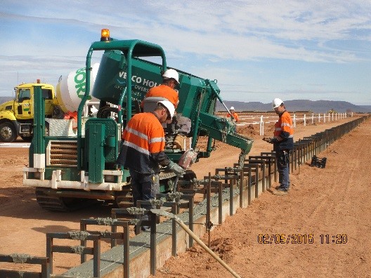
Further issues have now arisen relating to the welding procedures used by VDH. Hot water is supplied to the greenhouses to provide heating and is supplied by a series of insulated pipes, each greenhouse requires around 1800m of pipe which is supplied in 8m lengths and is welded together prior to getting lowered into the ground. The welders were brought in from Holland by VDH and started to work onsite on 27 Apr 15, with no notice given to JH. When questioned about this no ITP, welding procedures, proof of qualifications or hot works permit were produced, so JH was forced to suspend the works. On further investigation only one of the welders was able to provide his qualification certificate and this had expired. VDH then insisted that the welds were being done to EN13941 Class A standard. Part of this standard requires that the all full penetration butt welds joints are radiographed, when asked to produce the results of these tests VDH were unable to. In the follow on discussions it transpired that VDH were not testing the joints because they knew they would not pass; but it was ok because the welders have done this many times before and they rarely leak.
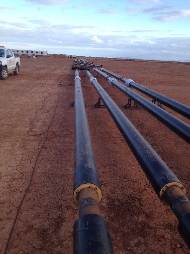
Insulated Pipes – In welding position and in the ground
The JH PM on site made the decison that in order not to cause further delays the welders could continue, but they were to produce a sample joint that was to be tested using magnetic particle inspection in Holland. This came to a head last week when the welders left site on leave and failed to return, preferring to stay in Holland where they can get guaranteed work and not be required to produce tests samples. Now VDH are in the process of recruiting a new team, with the correct qualifications in place, but clearly this is going to have an impact on time.
Van der Hoven Response
VDH are used to constructing greenhouses; they have a vast amount of experience across the globe but to date have worked directly for the client, usually a farmer. Therefore they are not used to working for a Tier 1 contractor such as JH and it is clear that their organisation is not able to cope with these additional demands. The VDH project team is currently split, with a PM and quality controller based in Holland (where the majority of the component parts are being manufactured) and a second PM in Australia. So far the PM in Australia has taken the majority of the blame for the issues on site; the first was a VDH employee who was sent back to Holland, the second was an Australian who was fired, and the third is another Australian, who took over last week. It should also be noted that the quality control role was implemented at the request of JH, as was the site safety advisor, prior to this there was no single point of contact for either within VDH.
John Holland Response
JH is also adapting as an organisation, on this project there is no organic workforce and JH is primarily managing subcontractors. The JH approach so far has been to give VDH as much support as possible both in terms of quality control and on site management. This has involved the preparation of documents as well as running workshops with individuals on site and via teleconferences. However this clearly comes at some expense in terms of time and resources to JH and so cannot continue for the next 12 months. In addition so far this approach has had limited effect and with future work activities including trenching, welding at height and the fitting of glass from raised platforms, it is an area that needs to be addressed urgently.
The Way Forward
The question is how do we now move forward? Should JH continue to produce the documentation for VDH or do we risk becoming a self-licking lollipop organisation? VDH are fully aware of what needs to be done in order to complete the work satisfactory to JH standards however they continually fail to do so. Is this a conscious decision on their behalf? I’m not sure, the amount of work it generates for both us and them makes me think not. But then again could VDH be lining us up for a massive VO or EOT claim, despite the contract clearly stating they must conform to JH procedures.
From my limited experience dealing local employed construction forces (by limited I mean watching via UAV feed as contractors tried to repair Bridge TOM at the same time as civilians were using it) and from Daz’s presentation on construction in Kenya last year, I imagine that many of the themes in this blog resonate with how construction is carried out in the military environment and will therefore become issues for all PET officers in the future.
Weekend Activities
I had a long weekend off a few weeks ago and decided to take the family to Port Lincoln, which is about 4 hours south west along the coast. The town is famous for sea food and diving with great white sharks, the latter of which I got the chance to experience and can recommend to you all.
Last Sunday I came in to work to work on TMR 1 away from the distractions of home: instead I ended up rounding up cows that had strayed on to site though the perimeter fence and were in danger of wondering into open trenches.
This weekend I took the trip to Adelaide about 3 hours south east, and took the opportunity to go to Ikea (hey!!).
