Archive
Any takers? Assistance much appreciated. There is no prize!!!!
Situation
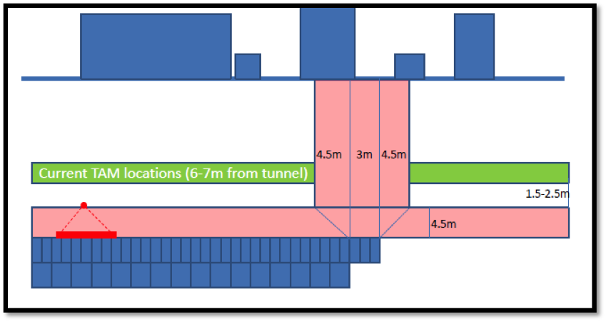
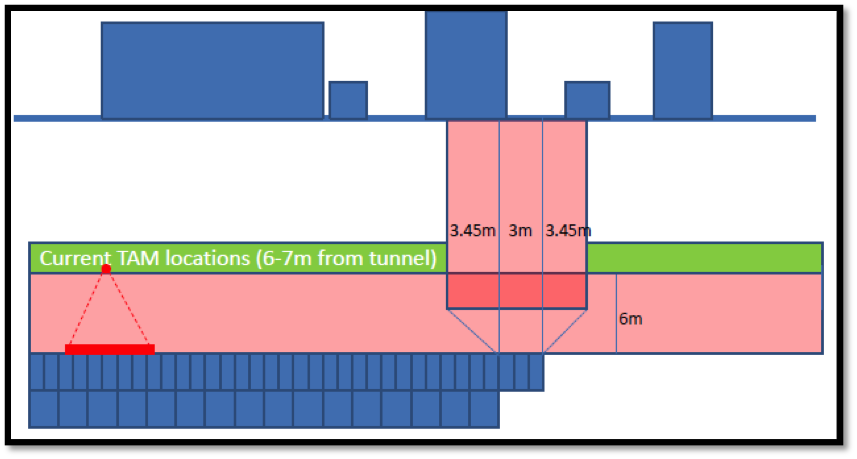
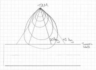
Have a look at the sketch below. As the tunnel is being excavated, above the tunnel there is a ‘umbrella’ of grouting (this is constructed using TAM’s, Tube A Manchette). The grouting is there to mitigate the settlement on the surface. However there are no grouting zone, that ensures the pressure from the grouting does not effect the exposed face (in this case 3 rings, 3m). The horizontal no grouting zone runs parallel to the tunnel at a depth of 4.5m, the vertical zone moves with the construction, however it’s dimensions are dictated by the exposed face (3m) and the angle that the TAM pressure influences (currently at 45 deg)
Issue
The problem is that the amber trigger levels have been hit, ref the surface settlement. The subcontractor want us to reduce the vertical ‘no grouting’ zone. This can only be achieved by reducing the angle from 45 deg to say 30 deg as the exposed face can not be reduced.
Calcs
If the pressure on the face is approximated as conical spread from point of injection. My preliminary calcs suggest that a reduction from 45 deg to 30 deg will impose a 300% increase in the pressure, as the area will reduce from 61m2 to 20m2.
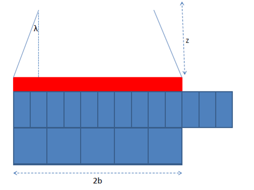
However this is a very rough approximation, as many of the stress counters from the TAM will be contained within the 30 deg. What Im trying to calculate is the % of stress that will be contained within the 30 deg compared to the 45 deg. Does this make sense? How the hell can I do it?
Train derailment at Stoke Lane on the 27th Aug 2013
This is a very short blog, as I don’t have time to go into detail. Yesterday I had a really interesting presentation on the factors behind the train derailment at Stoke Lane on the 27th Aug 2013.
Incident Overview
Nottingham train station was closed for a 6 week period, in this period company X tried to take this opportunity to lay some cables below the track (that was not operating as station was closed). In order to lay the cables they used some pipe jacking to lay a 1.2 m dia tunnel under the track. This required two shafts to be sunk, allowing the miniature TBM to be lowered into the shaft and jack the pipes in behind it.
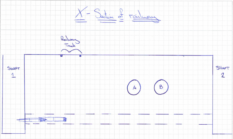
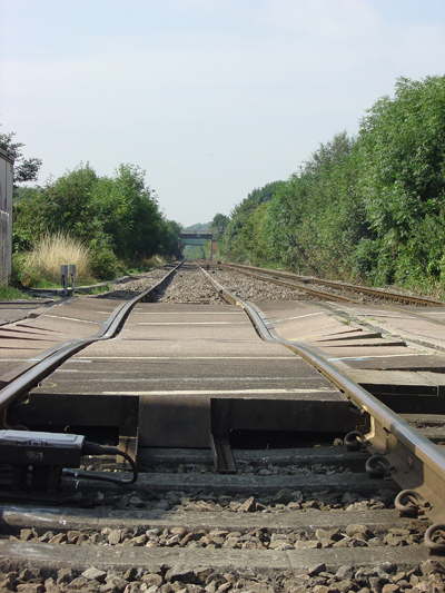
Several weeks later a train consisted of a class 66 locomotive and 30 bogied, tank wagons, loaded with diesel fuel. It was travelling on the up line towards Nottingham at a speed of around 53 mph (85 km/h) when the driver noted an irregularity in the track as he went over the crossing. Shortly afterwards, the trailing wheelsets of the 26th and 28th wagons derailed and ran for approximately 850 metres before the train’s brakes brought it to a stop, as air leaked from a punctured air reservoir tank. None of the other wheelsets were derailed. Both derailed wagons remained upright and there was no leakage of the diesel fuel but the track and some wagons suffered damage
Our involvement
As part of the Rail Accident Investigation Branch (RAIB), Donaldson Associates were asked to look into the method statement and design of a 1.2m diameter tunnel located directly below the area effected.
Findings
The findings are due to be released to the RAIB next month or so, however the preliminary findings are quite shocking. It appears that there was a number of factors that caused the derailment. I will try to explain just a few.
1) Most surprisingly, it seems that no one recorded the amount of spoil that came out the tunnel. It is now understood that twice as much spoil was removed compared to the volume of the tunnel. Where was this soil coming from? How did the contractors not understand that this was a serious concern?
2) The designers were not aware of the main line sewer pipes running above the tunnel until much later, after the tunnel design was completed. These sewer lines were carrying 4m3/sec of sewer, hence some substantial loading.
3) The depth of the tunnel was designed by calculating the live load on the rail way line, ensuring the crush capacity of the tunnel exceeded the live loading. It never factored in the weight of the soil between the railway and the tunnel.
4) The annulus (the space between the void created by the TBM and the concrete sections of the tunnel) of 25mm was not filled with grout or Bentonite. This would greatly increase the volume loss.
6) The volume loss in the design calcs was estimated at 1%, however empirical evidence shows it should have been around 2-2.5%.
7) The K value, that calculates the trough of settlement (Clay would be lower, gravel higher), used was 0.6, however for gravels it should have been around 1.2. This would have given a far deeper settlement in a more localised area.
8) Network rail (NR) do not allow works to proceed if the settlement is above 5%. If the volume loss and K values had been more realistic the settlement would have been around 7mm. Although this is nowhere near the 20mm settlement they experienced it would have been enough to stop the works in the first place.
9) Although the NR stipulate that there is to be no settlement in excess of 7mm, they do not stipulate any trigger levels. Additionally the company that monitors the tracks, recorded 20mm settlement, but didn’t do anything about it. There was no process in place to deal with the consequences.
10) The monitoring of the line only monitors the track. The soil below is not monitored. On inspection the track was spanning 700mm voids wit a span of 2m. No one was even aware of it.
As you can imagine the repercussions of this will be vast. The asset managers within NR are sure to have a busy time over the next few months. As a side point, the asset manager that signed off the works wasn’t even a ICE member let alone a CEng. Infact he had some random degree, yet was signing off works left right and centre. Sounds like he should join the RE (it sounds very familiar to my early days in the RE).
Retaining wall supported with a buttress
It seems I do have time to add another blog.
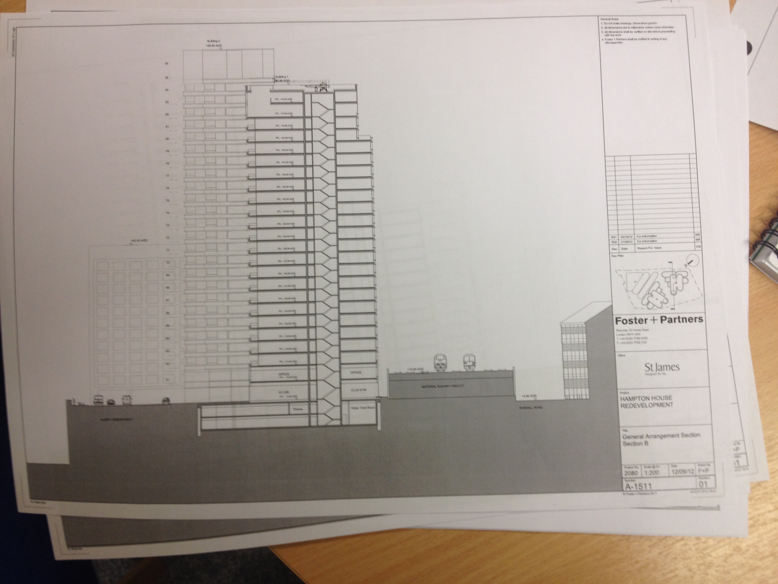
As I have discussed in previous blog, the pile group for the buildings were next to a railway track. In order to excavate the ground next to the viaduct, a retaining wall was required. However the retaining wall could not be supported by props as there was nothing to prop against. A a result the retaining wall was supported by buttress’.
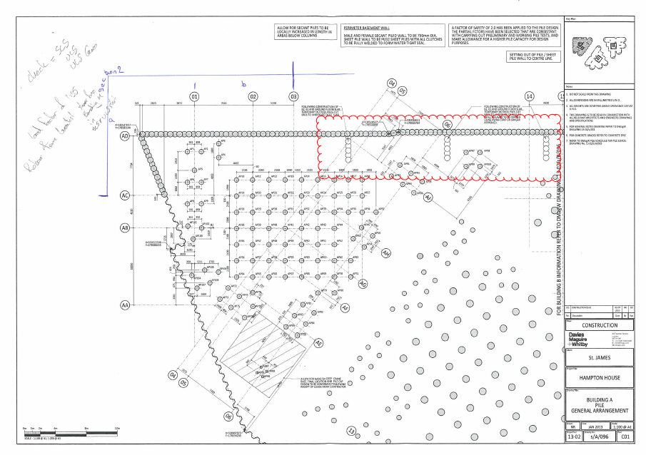
As you can see from the drawing above, the buttress’s are spaced by 13m and comprise of 4 x male piles and 3 x female piles. The spacing between the males are 1300mm. The original design allows for the female buttress piles to be installed to the depth of the retaining wall piles, allowing the male ones to go deeper to provide the stability. I was interested to find out how they had designed the buttress wall toe depth for the male piles. Here is a quick sketch of the way I calculated the resistance of the buttress piles.
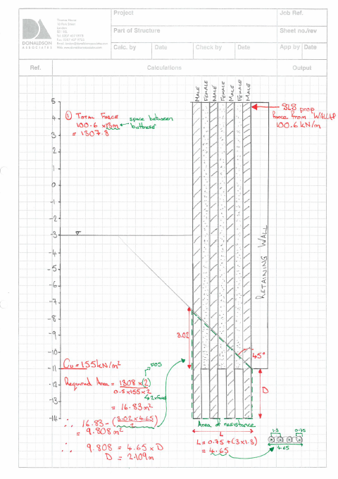
It seems to agree with Skanskas approach. However they had a toe depth of 11.6m, different to my 13m. I soon realised that they had made an error in their calcs, they had forgotten to work out the area of resistance correctly. Secondly I was concerned that if they were using L=4.65m, they should extend the length of the female piles to the same length as the male ones. The soil that is caught between the male-male piles would not create the same friction as male female pile combination. These factors have gone back to Skanska, I await their decision. I hope my suggestions are correct!
Piling Cat 3 check complete
This is only my second post since being on Phase 3. The reasoning for it has been this bloody Cat 3, external check, on a pile design. The deadline for it was the 14th, and then I took some time writing up my TMR 4, which happens to be about piling.
The pile design was completed by Skanska, for 3 x 30 story buildings. The buildings were sandwiched between the River Thames and a 4 track main route into Waterloo.
The first considerations that I looked into where the geological conditions. As London is located on, what use to be a sedimentary basin some 66 million years ago, much of the immediate ground is made up of clay. The clay is formed of both London Clay and Lambeth Group. What does that mean for the design? After some detailed revision of John’s notes and a little research I released that there is the potential for two events: Overconsolidation and Artesian pressure. The next question was, how can these effect the design.
Overconsolidation in the clay meant that there was a high probability of anisotropic properties in the soil, this translated into a Overconsolidation Ration (OCR) of potentially 5-6. Hence I could have differing values for soil properties such as strength and stiffness, depending on the plane in which I was analysing. This also meant that as we excavated the soil, we could expect much more swelling than would otherwise be expected. This would cause excessive swelling, much more than would be expected from elastic swelling. Hence there would be heave on the piles, however the piles would experience differing amounts of heave as the stiffness of the soil would be greater, the deeper the pile was. This would cause a stretching effect on the pile, which would need tension reinforcement.
Secondly if Artesian pressure was present in the lower aquifer, which is contained in the Thanet Sand and chalk, there might be a need for dewatering to reduce heave on the piles. Clearly this would only be necessary if the piles where penetrating the lower aquifer, hence they would have to be long piles. As a side note, the Shard has 200ft piles which did penetrate the lower aquifer, however there was no Artesian pressure in that area (due to historical welling taking place).
On top of both of these geological considerations, I was dealing with Clay. Therefore I had a long term and short term analysis to consider. In the short term (undrained) I would be using total stress parameters, such as Shear Strength (Su). In the long term (Undrained) I would be using effective stress analysis and properties such as Effective Cohesion (C’) and Effective friction Angle.
I knew that the pile resistance was calculated using the Shaft Resistance and the Toe bearing capacity. Hence I needed to use:
Shaft resistance = Cu N
Toe bearing = alpha.Cu or a more accurate effective stress analysis equation which I can’t write down as I haven’t got time (John you will see it in my TMR)
So the first step was to conduct the same stages as we did on Ex Cofferdam. Look at the boreholes, compose a worst case scenario of the cross-section the piles would be penetrating. From there, I created a spread sheet. The columns included, depth, depth of strata, soil properties, end bearing resistance, shaft resistance etc. The next step was to apply the factors from EuroCode 7. This gave me the ULS 1, ULS 2 and SLS combinations. It turned into a mammoth spreadsheet, I might get it framed.
I then looked at the actions on the piles, from the column loads. Applied the factors giving me SLS,ULS1, ULS2 and compared these to the previous results. If the actions where smaller than the resistance from the soil, the piles where OK.
The last check was the structural capacity of the pile. I needed to check the reinforcement in compression, bending shear and tension (as previously described). This required the use of the Broms equation, to turn the horizontal loads (given in the piling schedule) into moments. For each check, I used Eurocode 2 and Rich Farmers notes on column design to guide me through. I designed the piles as short stocky piles, as the effective length was minimal as the soil supported the column/pile the entire length. As John Moran suggested, as long as post holing does not occur, this design method seemed appropriate.
The next stage was to analyse the retaining wall, which was supported by buttress’. I have got time to do this justice, so I will explain this in the next blog next week. It was surprising interesting, so I will produce a few sketches.
Burton out!!!
Second Week at the design office
After arriving last week, it has been none stop. Initially I found myself updating the drawings for Fisher Street (the Crossrail project).
However that only took a day, I was then tasked with doing a Cat 3 (external) check on some pile calculations. I was already worried about this task, then when I found out that the boundaries consisted of: 4 track line into Waterloo, Thames River and a 25 storey building. The most worrying of these boundaries was the railway line. The 4 tracks were positioned on a old brick viaduct, that had a 5mm capacity for settlement. Then I found out that the piles where for 3 x 30 storey buildings.
So I have now completed my calcs according to Eurocode 7. Initially I created the worst case scenario of the ground strata that would be encountered by the piles. From this I calculated both the shaft and the End bearing capacities of the piles. This was done by creating a spreadsheet (similar to the ones we did during phase 1) that has been setup, that all I have to do is input the dia of the shaft and the dead and live loads placed on the piles.I have then carried out a settlement calc using the Wallup software and the Tomlinson & Woodward approach. This has included both the long term and short term assessment. Both these conditions required differing inputs for the Clay and the stiffness of the wall (Secant Piles). I am now awaiting Skanska’s design to see if it comes anywhere near my cals. I hope they do!!!!!
The other big difference here is that each minute of the day has to be accounted for. That means that you have to submit a breakdown of the time you spend on each project. No more sending messages to Rich Phillips during the day, not if I want to keep the illusion of working.
WOW!!! has it been that long
I can’t believe it has been that long since my last blog. Things have been quite busy here for me, however the site has progressed slowly. The original completion date for the shaft was the 9 Sept it then moved to 31 Oct, 7 Nov, 17, Nov and now it currently rests at 27 Nov. My hope is that I will see the final shaft construction complete before I leave for the 3rd phase placement.
As you can see from the overview below, we have only completed a very small part of the Fisher Street works. Once the Shaft has been completed the Crossover section will begin, taking approx 1 year to complete.
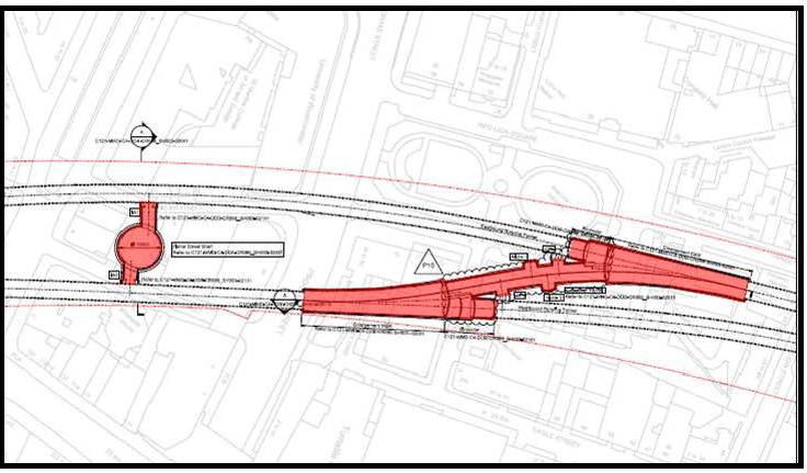
The process that we have used for the vertical excavation of the Shaft will be repeated for the horizontal sections of both the Adit eyes (the connection between the running tunnel and shaft) and the Crossover.
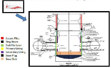
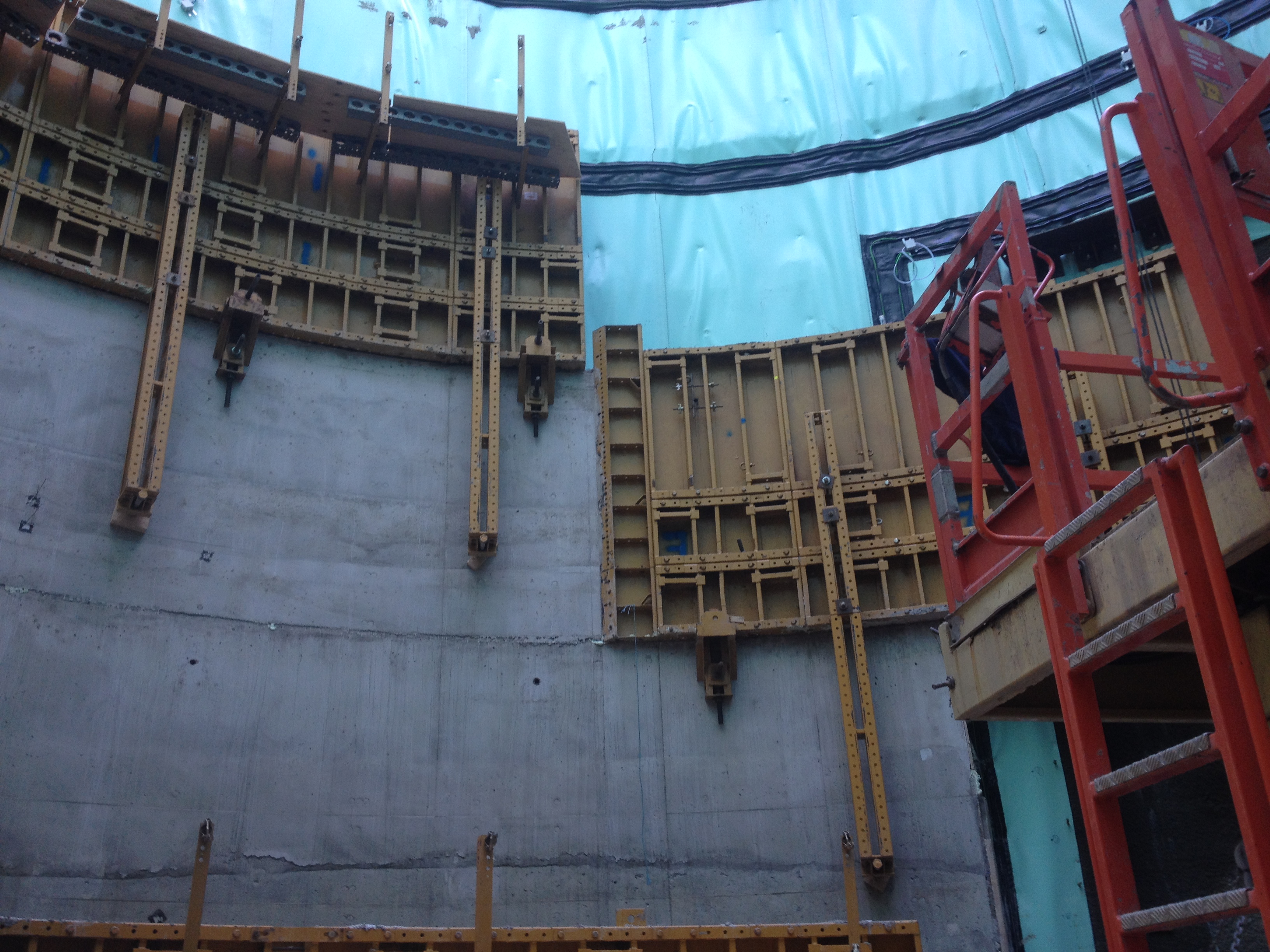
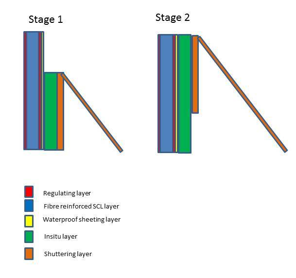
Looking in detail at the shaft there have been a number of phases that have been completed to ensure the overall success of the project. We are finally placing the Secondary/Insitu lining that will see the shaft completed
However, as all ways, it has not gone that smoothly. The idea was that a meter high ring would be poured each lift. Once the ring had reached a specific strength the shuttering would be lifted and another pour completed.
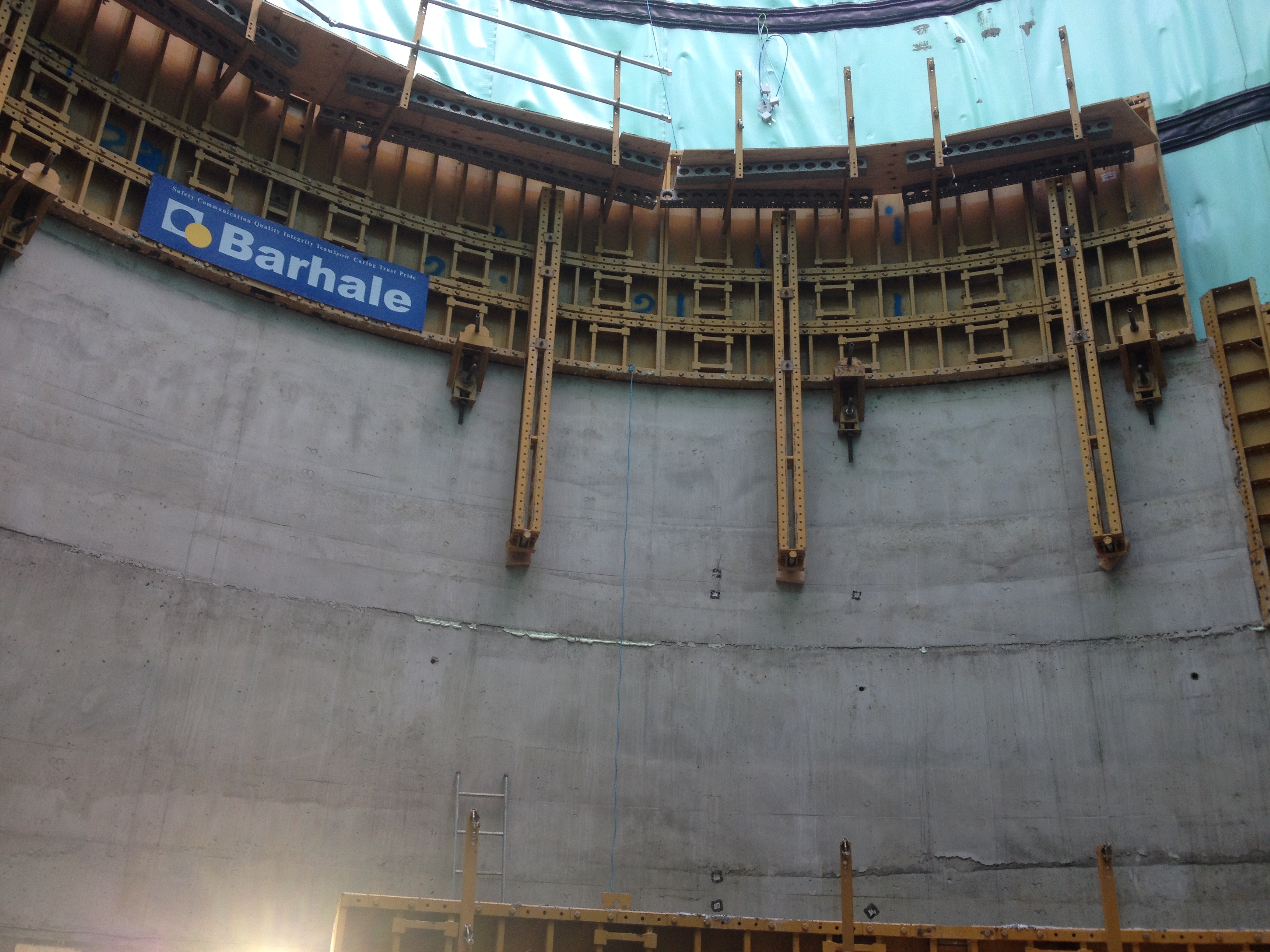
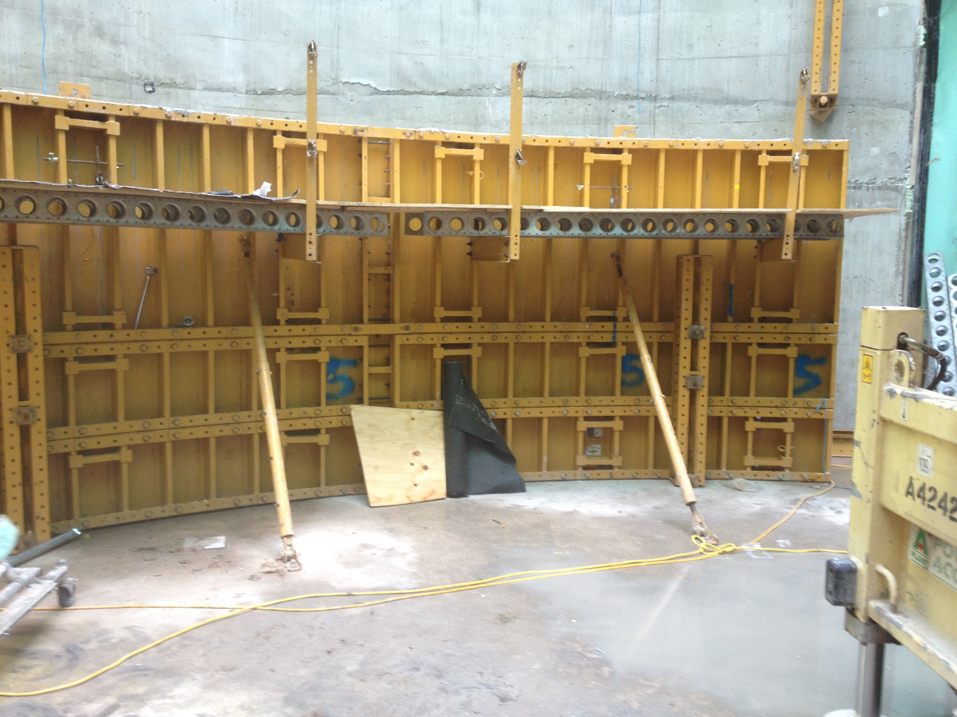
The plan was to complete three lifts per week. We have only achieved 1 per week. This has been due to a number of issues: cold joints being formed due to poor concrete delivery planning, cracks in the surface as Barhale forgot to spray the curing agent and the time it takes to deconstruct the shuttering and raise to the next level.
Whilst this has been going on I have been planning for the next phase. This has involved liaison with Camden Council again in order to secure a Section 61 for the Crossover works. Ordering new equipment, as Barhale leave on the 27th Nov along with all their equipment. Ensuring the new equipment is calibrated and conforms with the appropriate BS and CRL specs.
The planning of the next phase has raised other issues. The most significant has been the delivery process of concrete and ventilation to the Crossover Section. As a result we have had to enter Kings Tramway Tunnel (KTT) that runs perpendicular to the running tunnels. We are in the process of drilling holes from the KTT into the running tunnels, allowing ventilation and concrete delivery. The paperwork required to undertake works in a listed tunnel, such as KTT, has been vast. Not only are we producing Method Statements and Inspection Test Plans (ITPs) for Adit Eye breakout, Frame installation , Enlargement of the running tunnels etc, we are also producing documents for London Heritage. Nightmare!!!!!!
Although on the positive side of things TMR 3 finally got handed in and I have started work on AER3. Additionally I was collecting money yesterday for the London Poppy Appeal. Started at Fenchurch station at 0600hrs untill 1700hrs, raised a lot of money. As a reward went drinking with the Chelsea Pensioners, WOW they can drink!!!
No concrete!!!!!……………Again
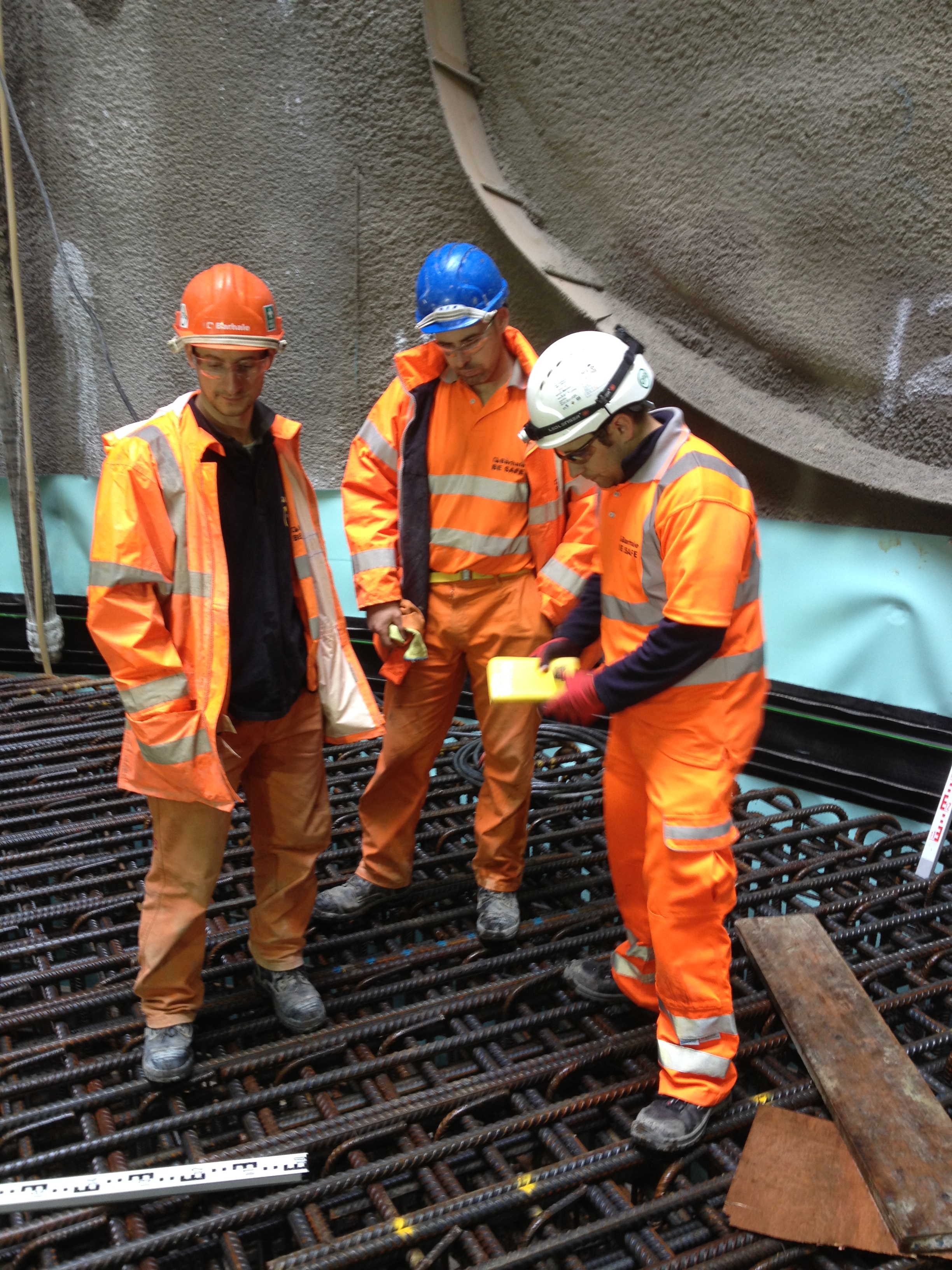
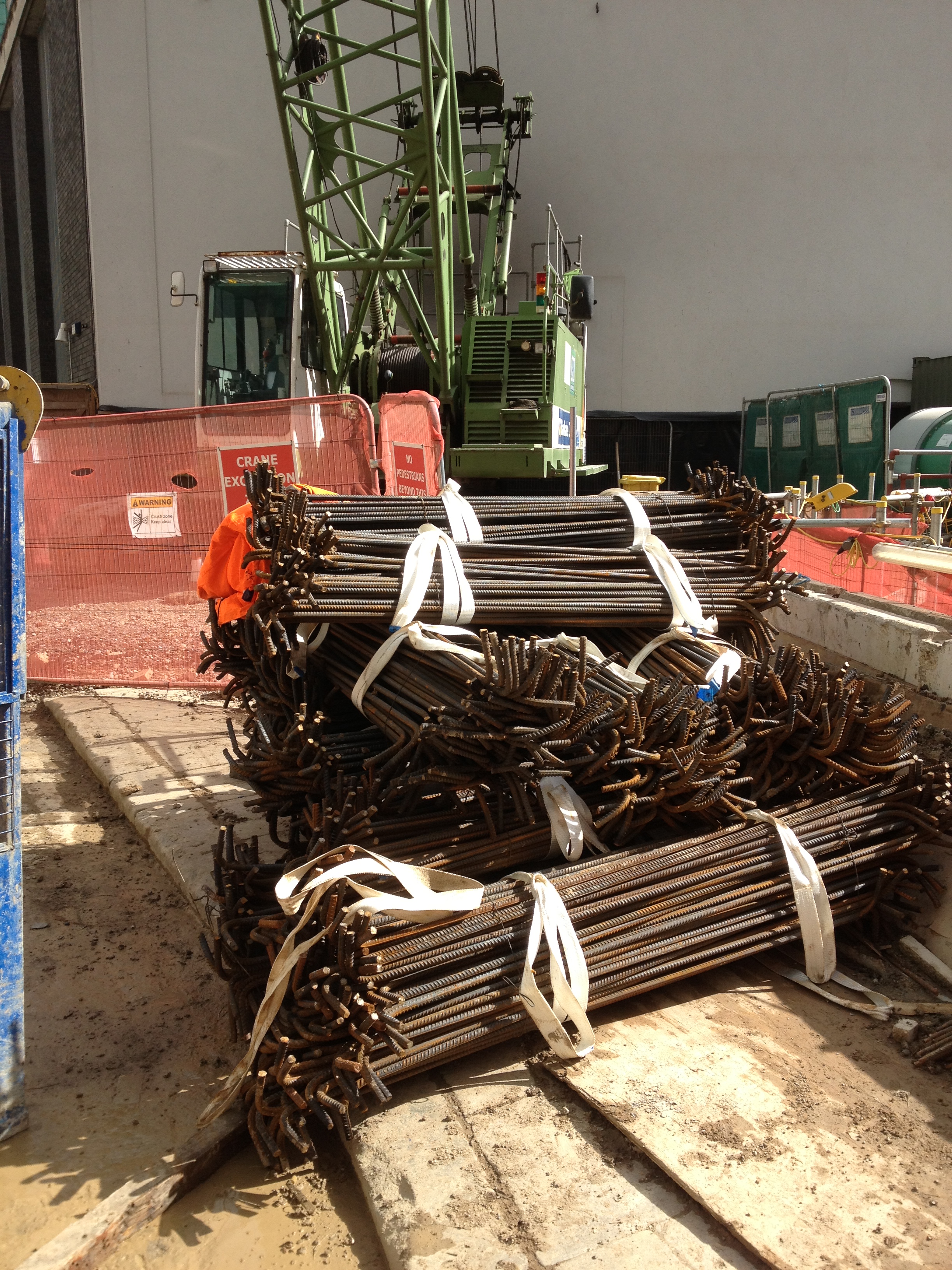
The last post finished off at the point of the base plug being poured and the Waterproof sheet membrane being fitted to the shaft bottom. This week has seen 75T of steel being fitted into the base prior to the “2nd” base slab being poured.
Base Plug pour
Waterproof sheeting installed
Whilst the job of installing the rebar has been taking place, the new Sub Agent (Filipe) and I have been trying to coordinate the next two phases. The next phase in the construction of the shaft is to pour the base slab (430m3). However there have been a number of issues. The Concrete mix design that was submitted by the Sub Contractors (Barhale) failed to reach the spec required by KF10 ( Materials and Workmanship Spec – In Situ Concrete). This is because it had not been tested for ‘Dry Shrinkage’ . The result of this has meant that I have been going through legacy concrete mixes, approved for other component ie Piling, Ring Beam to see if the mix complies with KF10. However there is no mix that has been tested for Dry Shrinkage. As a result the construction could be placed on hold for 90 days whilst a new concrete mix is designed and trialed/tested (requiring 90 day results) or continue with the pour and hope that the samples taken today reach the ‘dry shrinkage’ requirements in 90 days. THerefore I have just sent them this recorded Email:
‘1. They have failed to provide a mix with the appropriate testing information to confirm compliance with the relevant specifications (KF10) 2. It is their decision to proceed with pouring the base slab with a non compliant mix, and therefore is their risk 3. Any remedial works that are required to be carried out as a result of excessive shrinkage occurring will be covered entirely by Barhale 4. They will need to take appropriate samples at the time of the concrete pour and organise testing to confirm compliance of the placed material with relevant standards (KF10).’
Fast forward 28 days and hopefully the base slab will be poured, it will pass the dry shrinkage tests and the remainder of the shaft is waterproofed with sheeting. At this stage the In Situ lining will be poured. Amazingly again Barhale have failed to provide a concrete mix that reached the KF10 requirement. Again myself and Filipe have tried to recover the situation. THe only mix that complies with the In Situ lining requirement is the Segment mix. This mix is designed with a 30min life cycle. THe idea being that 250 pre cast segments are produced each day at Old Oak common. These segments are then delivered to site. However in our case we need to get the wet mix to Fisher street and let it cure in situ. Clearly the life cycle needs to be extended to approx 4hrs. This requires approx 4% retarder, however this is a change in the Mix design. AS a result we need to carry out trials and testing, hence I am going to Old Oak Common on Monday to pour 4.2m3 of “Segment Mix” and 5.5ltrs of retarder and probably an extra 50ltrs of water (the water is required as our mix will be pumped and the segment mix is too dry for pumping). Hopefully I will be able to record the correct slump (S4) and the correct life cycle (approx 4 hrs). If I can do this I will pour it into 3 x panels, then Test Consult (concrete laboratory) can collect the panels and carry out the required testing (Compressive strength, water penetration, dry shrinkage etc). CRL have agreed that if the 7 day results are OK then we can use the mix for the insitu lining, as adding retarder should not effect the qualities of the already approved “segment” mix. As you can see, how it has got to this position I do not know. I would have thought that before the shaft construction went ahead, someone would have double checked that we had all the required mixes in place and ready to go. Im being a little harsh, as the detail of this saga is a little more complex but unless Filipe and I can produce a concrete mix with 4 hrs life cycle and a S4 slump, the shaft project will go on hold….again.
However on a positive point, Im off to the ICE presentation on the London Super Sewer in an hour and Donaldson Associates have accepted me for my 3rd phase placement, meaning I will be located at the base of the Shard by Jan next year.
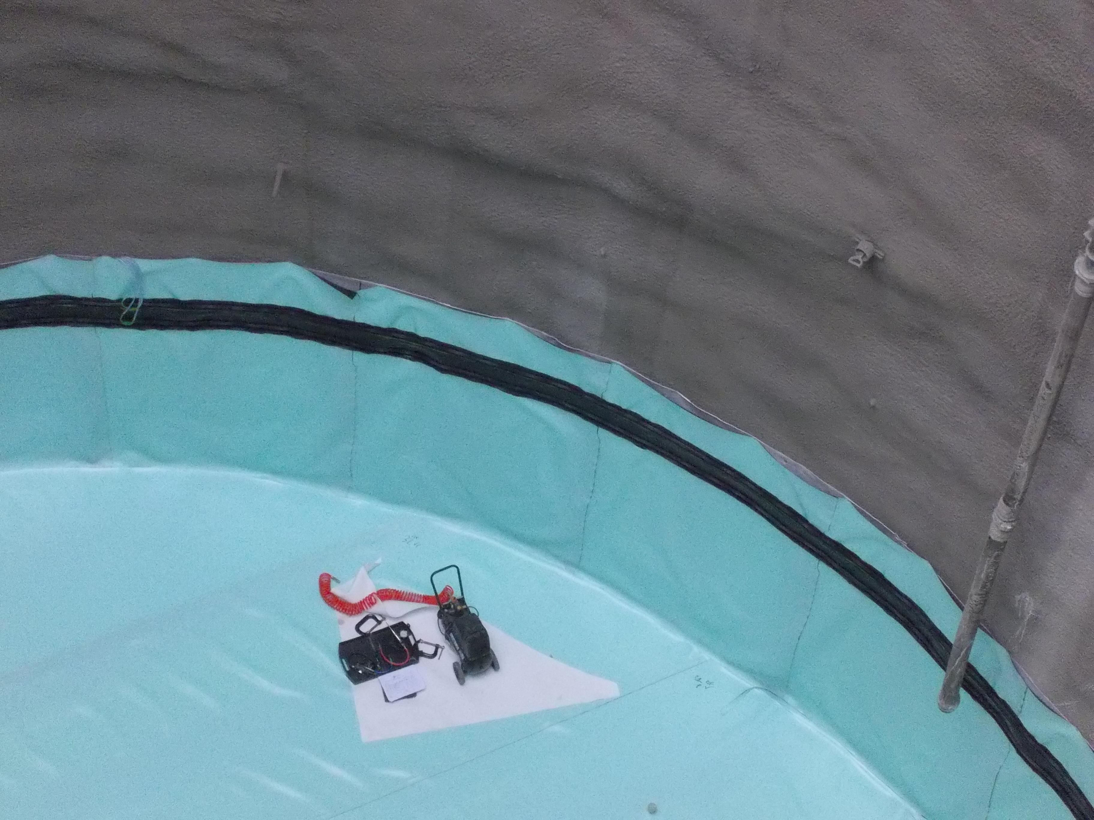
My Big Swimming Pool
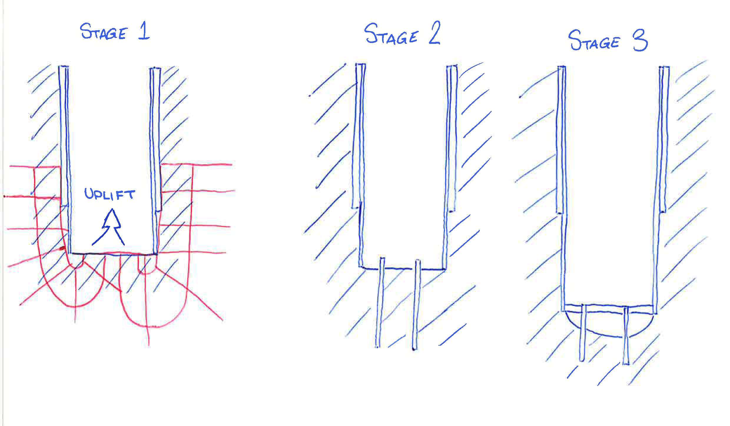
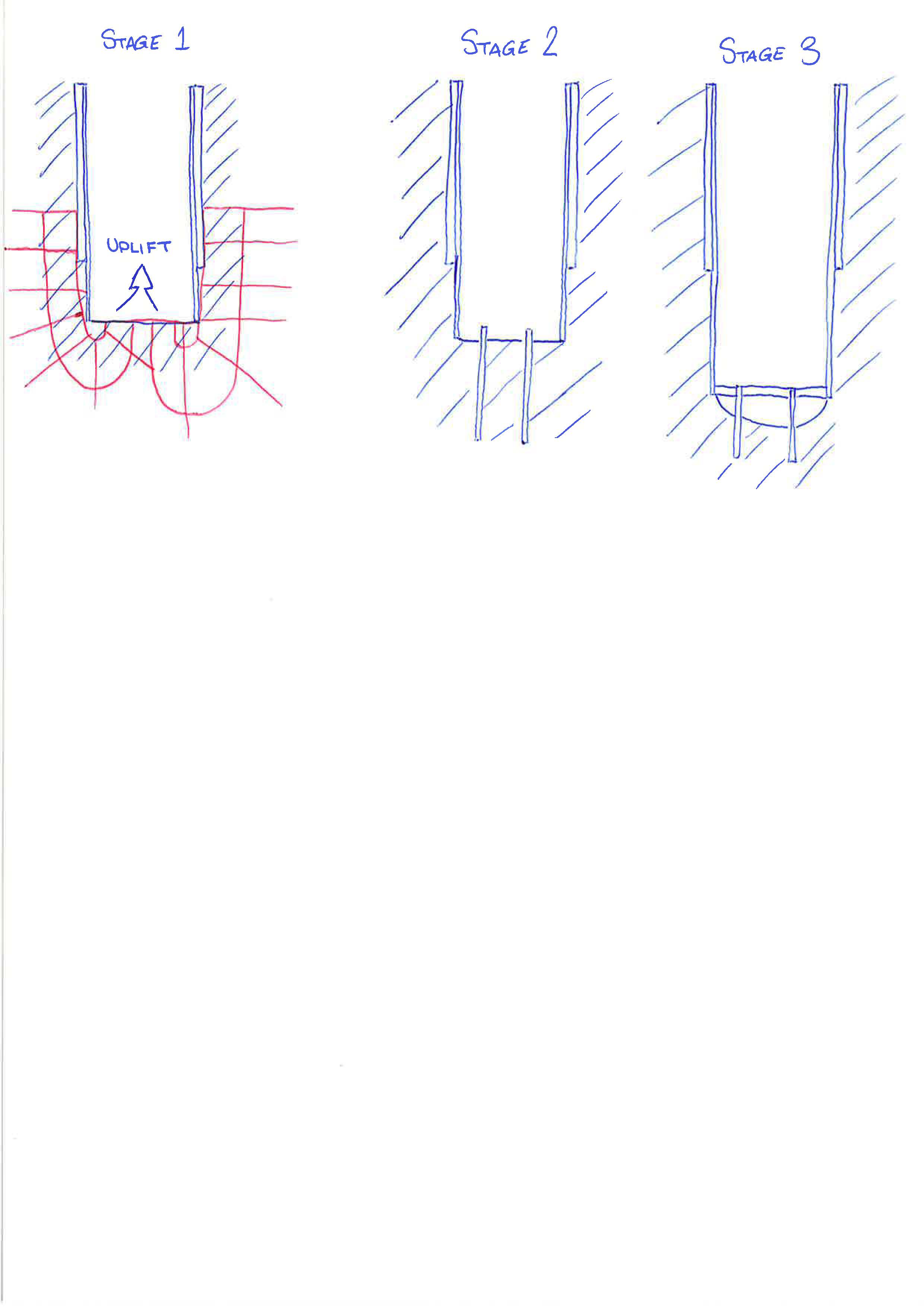
As I mentioned in the last blog, the SCL works for the shaft are now complete. As a result the base plug, some 230m3 of concrete was poured to ensure there was no effect from the uplift heave. The plug was left to cure and then the 3 x depressurisation wells were grouted to seal them.
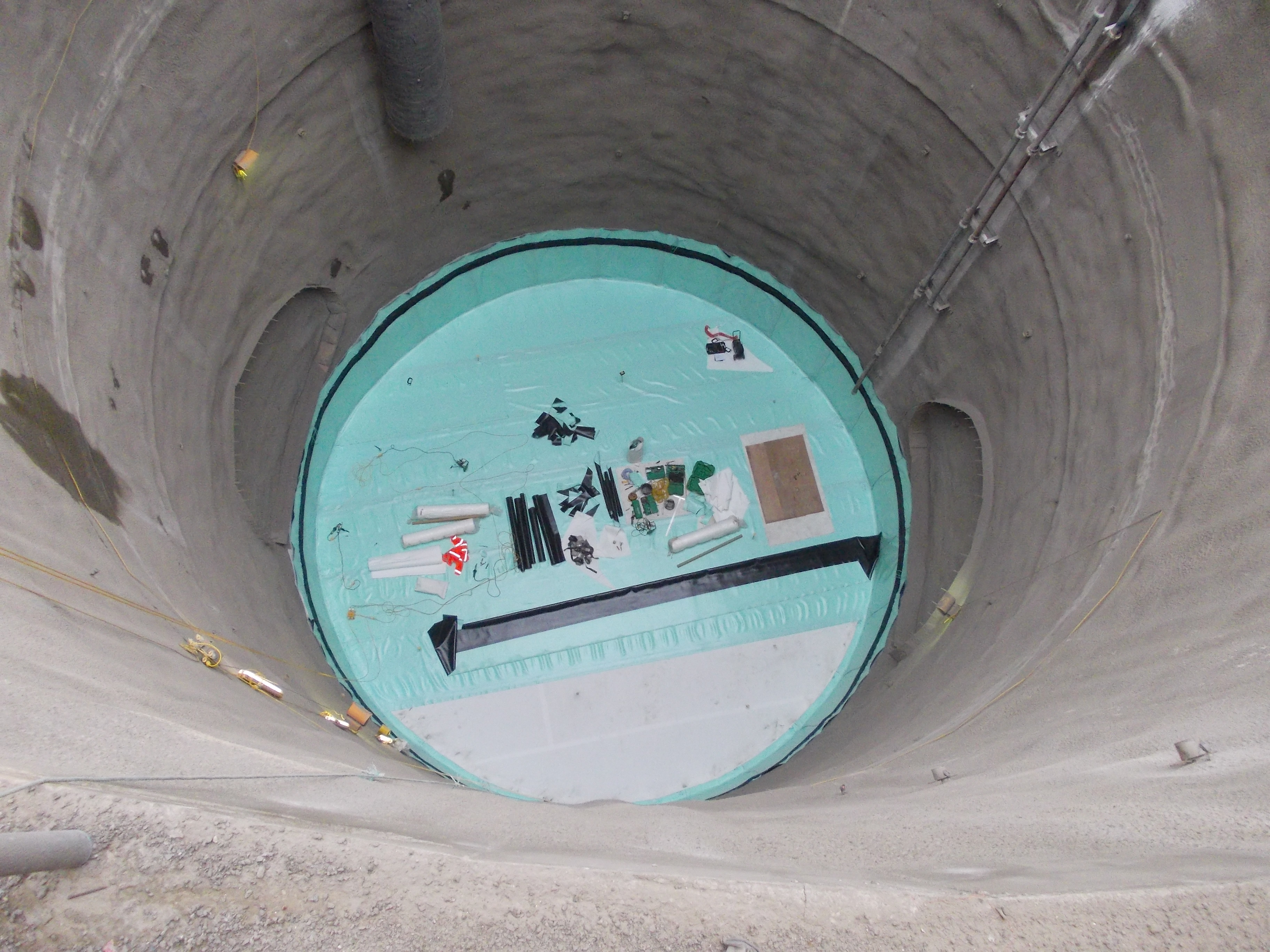
The next phase was to start installing the waterproof sheeting. However this could not be put in place untill the protective layer was installed. The protective layer is essentially a sheet of thin white foam. The foam stops the steel fibers that are in the SCL from penetrating the waterproof sheeting.
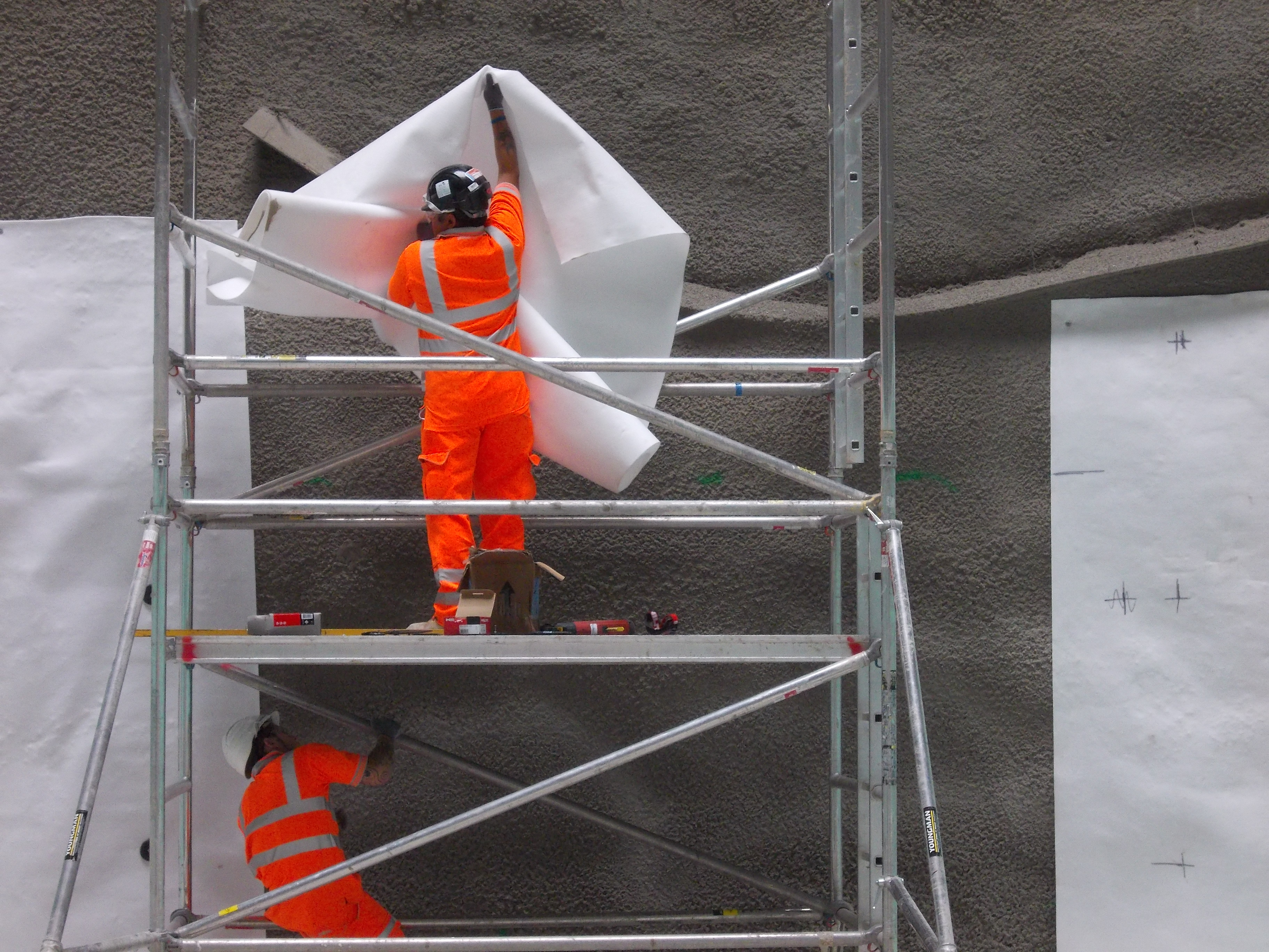
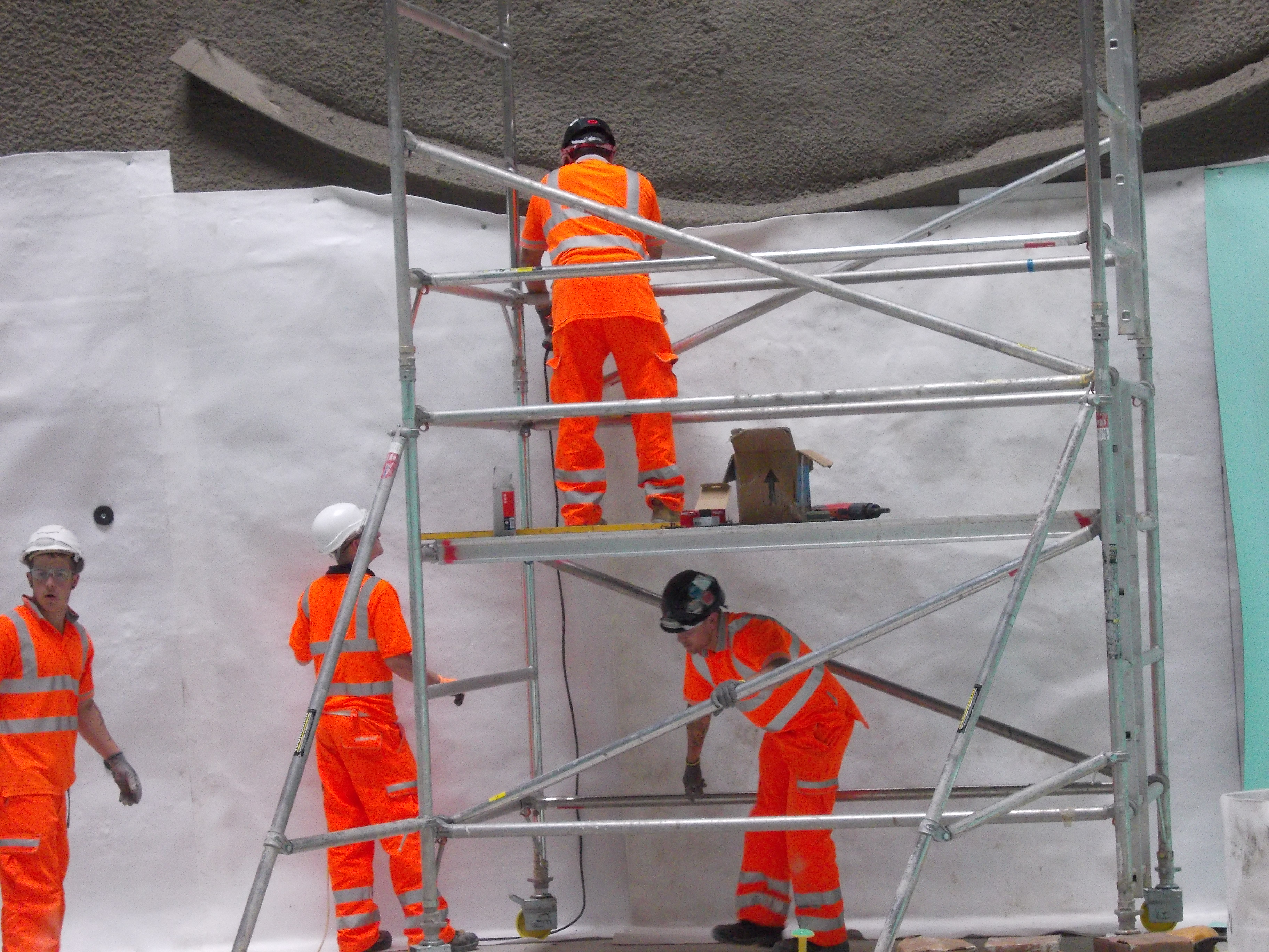
The protective layer is nailed into place, allowing a large washer to be installed allowing the waterproof sheeting to be welded. This ensures that the waterproof layer is never punctured by nails.
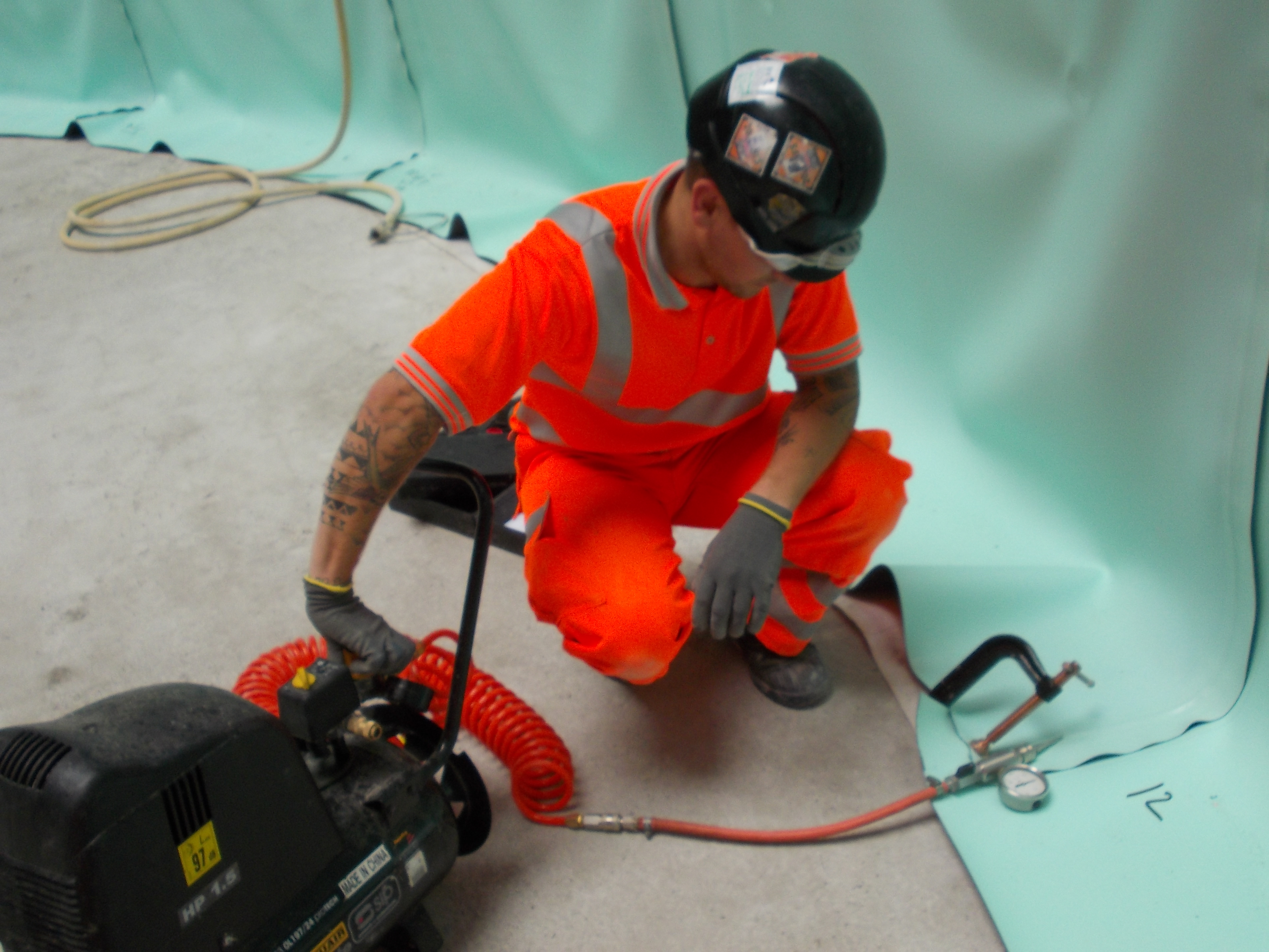
As you can see from the photos the waterproof sheeting comes in rolls of approx 2m. As a result the sheeting needs to be heat welded to each other to ensure a watertight fit. To make certain that the waterproof sheeting has been welded together correctly the joints are pressure tested. The overlap between each sheet is filled with air and the pressure is taken for 10 mins. If the pressure decreases the seal is not 100% perfect, as a result the weld is redone.
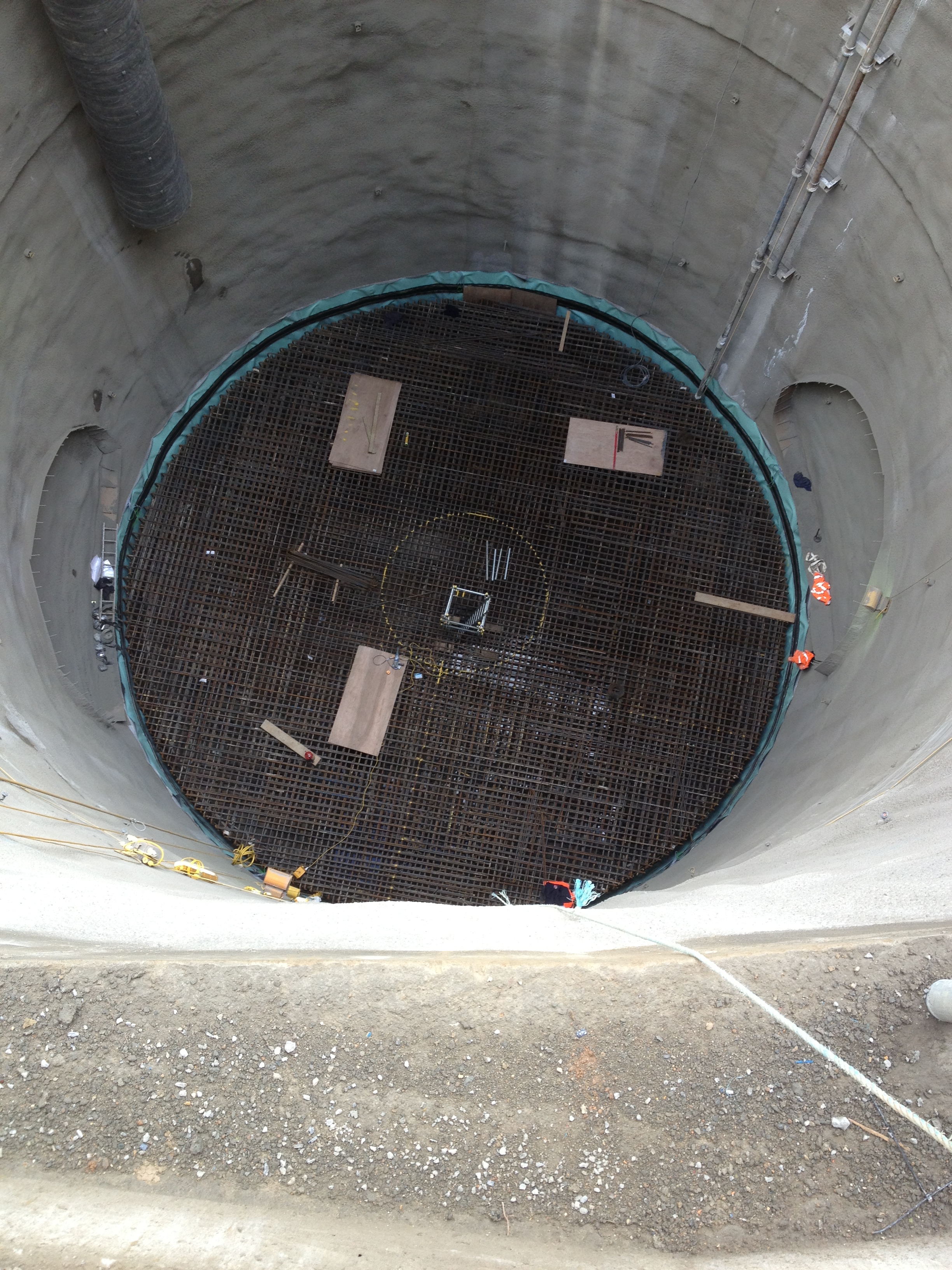
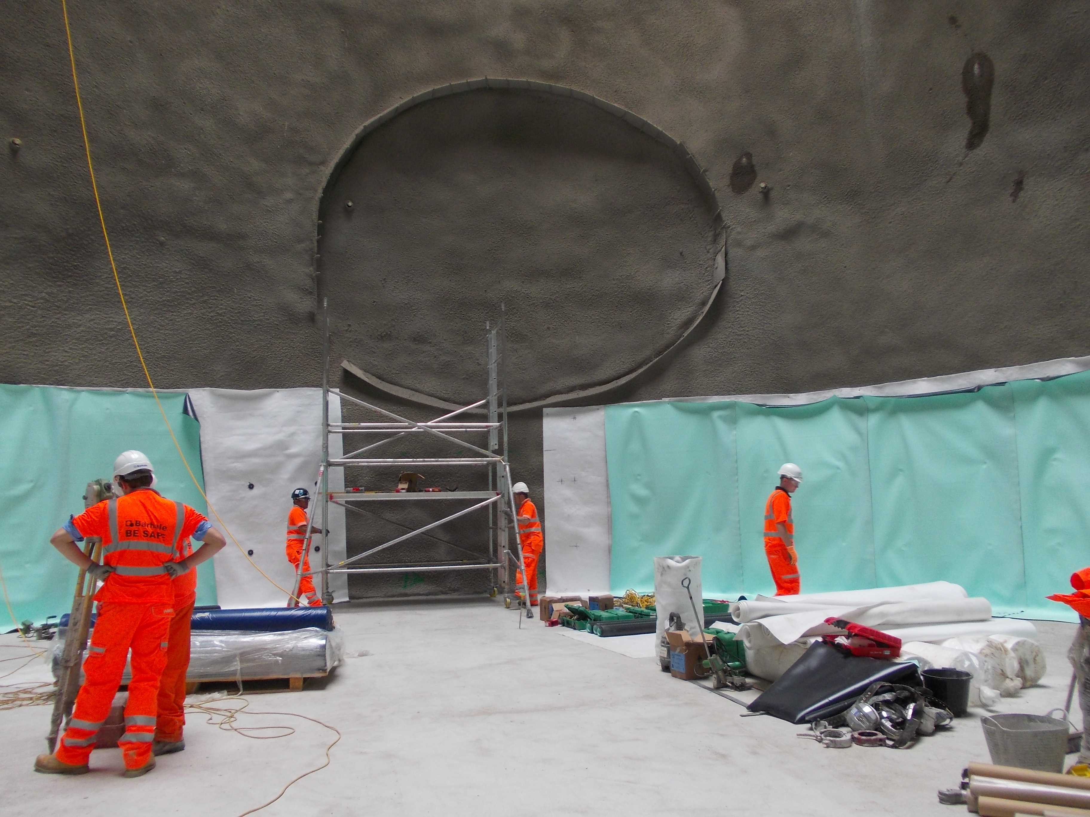
The final result is that the base is looking like a giant swimming pool.
The next phase is to install the huge reinforcement cage into the base and then pour a further 450m3 of concrete. It seems like a huge overdesign but the designers have insisted on the second pour. Once the second pour has been completed we will be at the Adit level. This will be the point that the waterproofing for the shaft sides will be installed, shortly followed by the Insitu lining.
On a different point, Gemma Quickenden (Sub Agent) has now left the project. This has allowed me to take over the running of the Compensation Events. With the completion of the SCL works the SCL CE’s are being dealt with. I arranged the first meeting with Barhale yesterday to talk through all their CE’s. I had hoped we could agree on the majority of the 26 CE’s however we have agreed upon 5. This has been the most enjoyable part of the secondement so far, as it allows you to debate/argue with those individuals you have been wanting to shout at for the past 6 months.
Shaft complete……..almost!!!
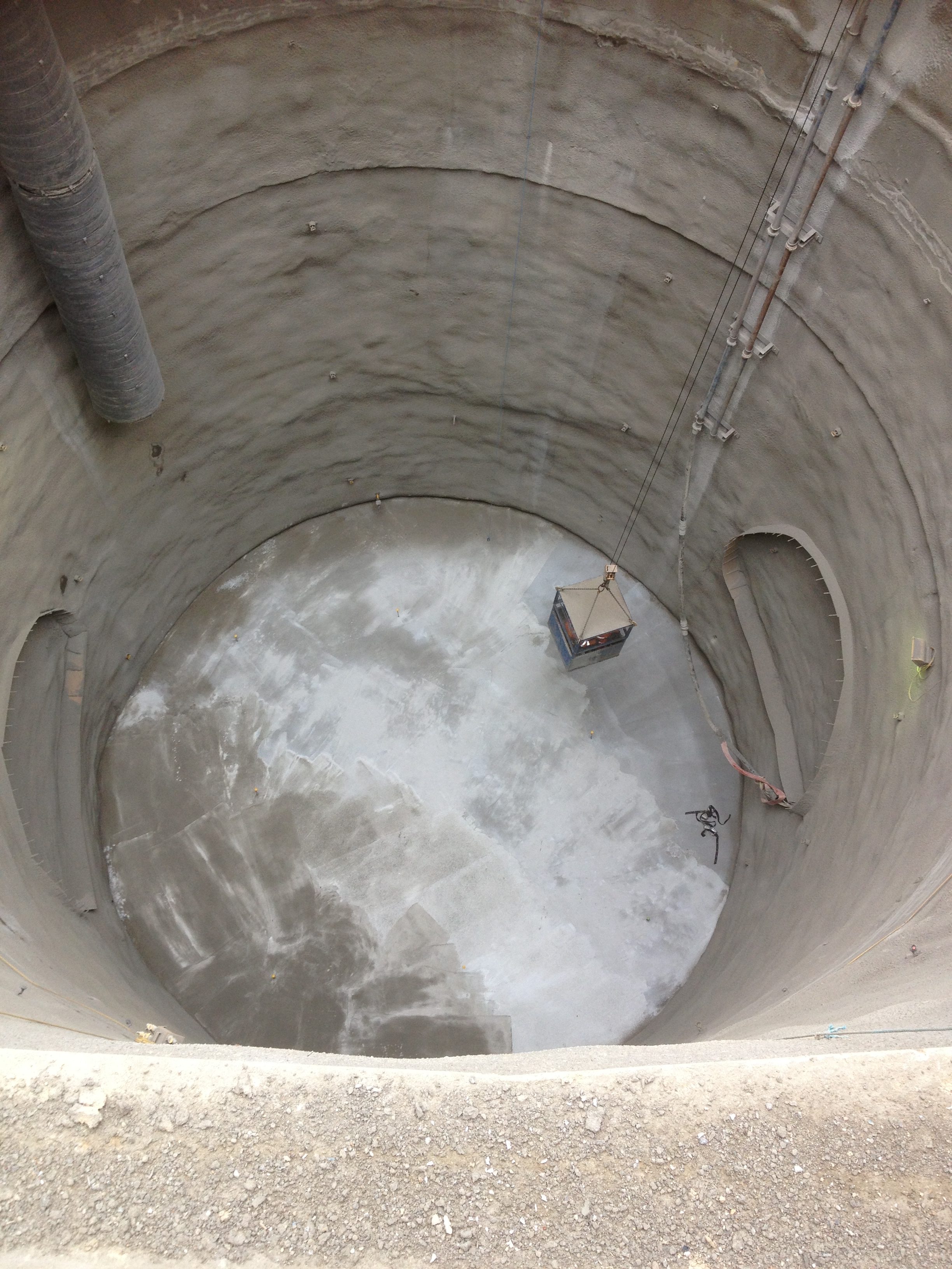
Finally we have got to the bottom of the shaft. The excavator has been lifted out of the shaft, allowing the base slab to be poured.
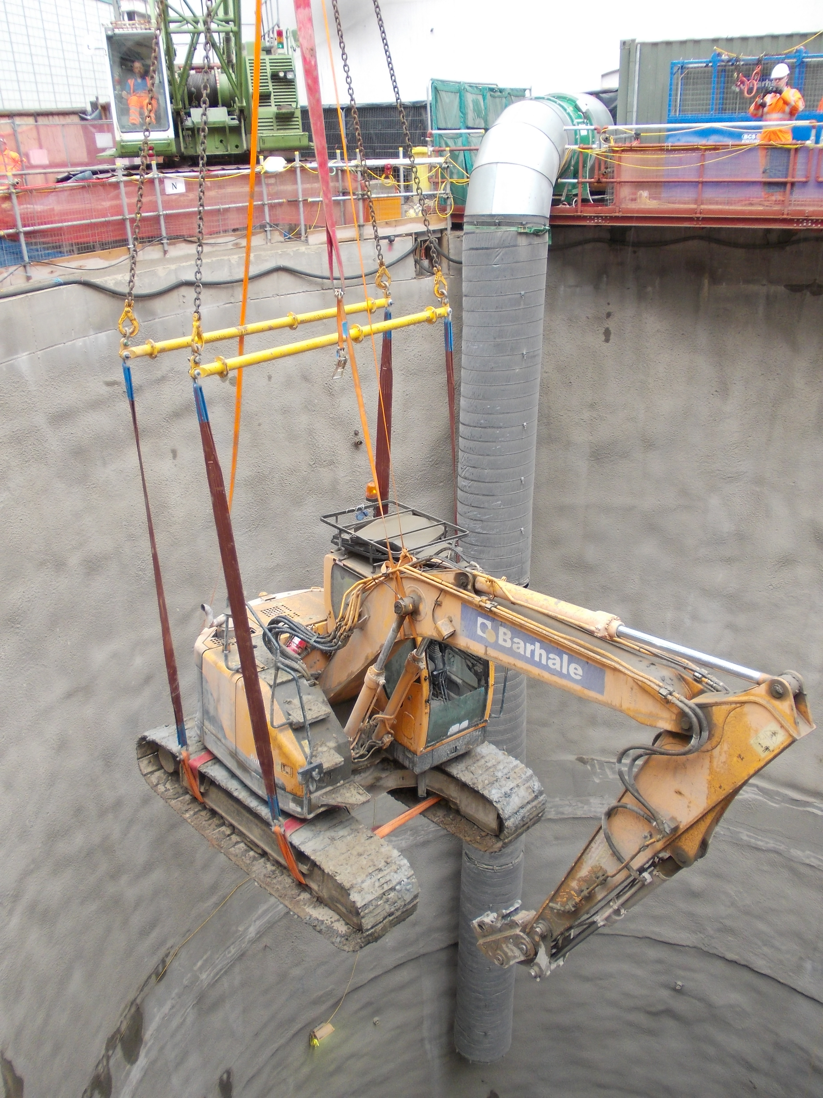
So what is the next step?
Well the Waterproofing sheet membrane needs to be installed over the slab and the walls of the Sprayed concrete lining (SCL). However the water proof sheet membrane requires a regulating layer to be sprayed over the reinforced SCL as the steel fibres could pierce the sheeting allowing water ingress. THe waterproofing sheet will be lowered onto the slab and a huge sheet will be rolled to the top of the shaft. Once it has been nailed in place the sheets will be welded together using a heat roller. Once the sheeting has been sealed and connected to the shaft it will be tested for any leaks. They use compressed air to find the leaks, much like looking for a puncture in a tyre. The gap between the sheeting is filled with compressed air, if the pressure decreases…you have leak.
Once the waterproofing is in place the next step is the In Situ lining. The concrete will be the first non sprayed concrete we have used since the installation of the ring beam. The concrete will be placed into position using ‘climbing shuttering’. This will allow the first lift of concrete to be poured, once that has cured and reached the correct compressive strength, the shuttering is raised into the next position ready for the following pour.
So far the project has run relatively smoothly, however with this new waterproofing material I predict a few issues next week. Additionally, we are still trying to find a concrete design mix that fits the required specification for the In Situ lining. So far the concrete design that was selected by our Sub contractors has failed to reach the specification. AS a result I am trying to find a legacy design that meets with the spec, however they are mostly falling short. The major culprit for this seems to be the amount of polypropylene monofilament fibre and the drying shrinkage requirements. Hopefully we will find a mix before the 26th, when we start pouring. unfortunately, the one design that did meet the spec had a working life of 30mins and it takes 45mins to get to site from the batching plant. The amount of concrete required is a problem area as well, as we need 60m3 every 3 days, not many of the batching sites can provide with their current work loads.
Any way I shall let you know how it goes next week. The good news is that the Sprayed Concrete lining is complete and the slab is being poured as I type. Nearly there!!!!
Water Depressurisation
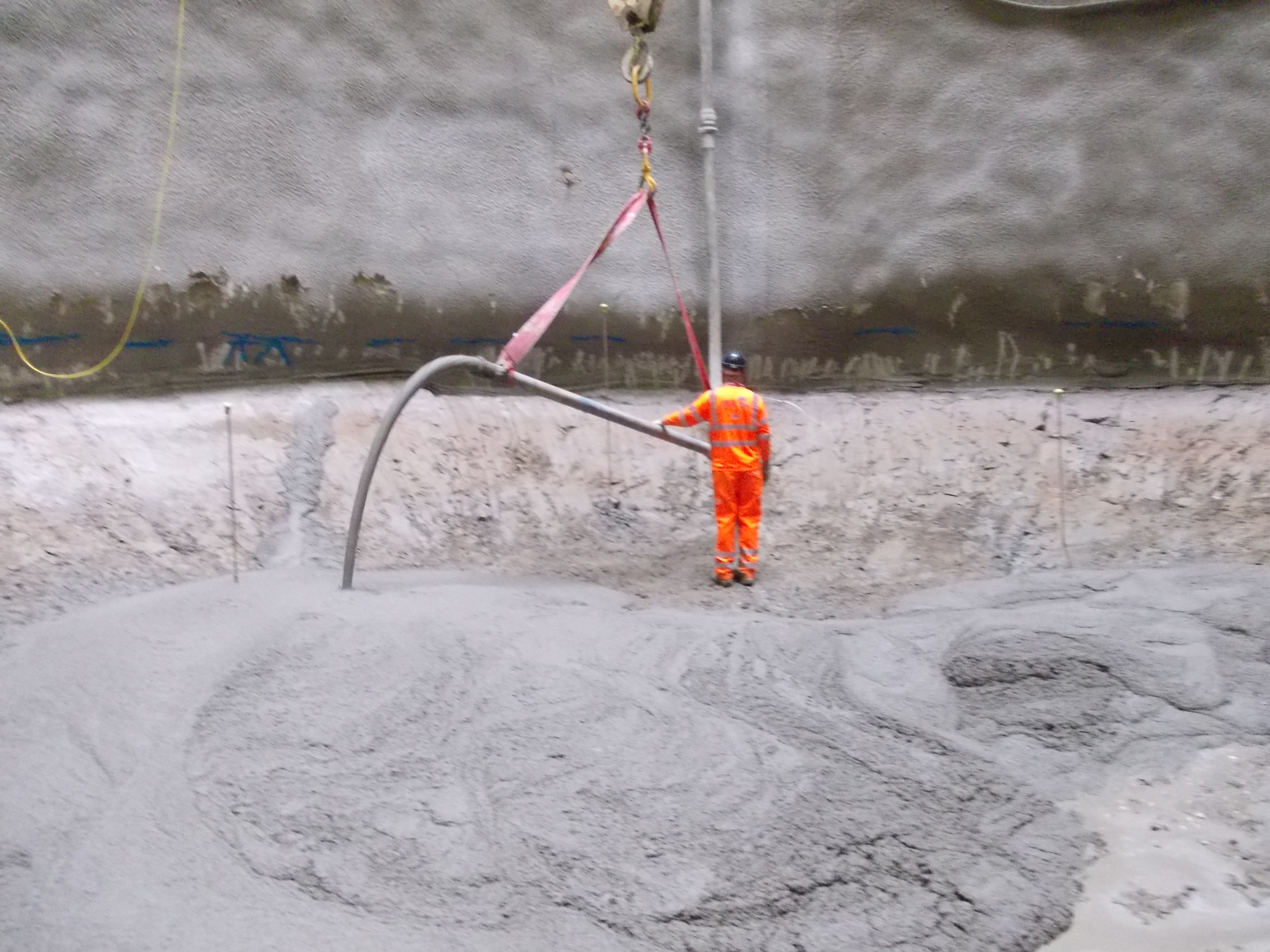
Second week back from summer hols and things are progressing nicely. The shaft construction is becoming a bit repetitive so I thought I would give the spraying a go for my self.
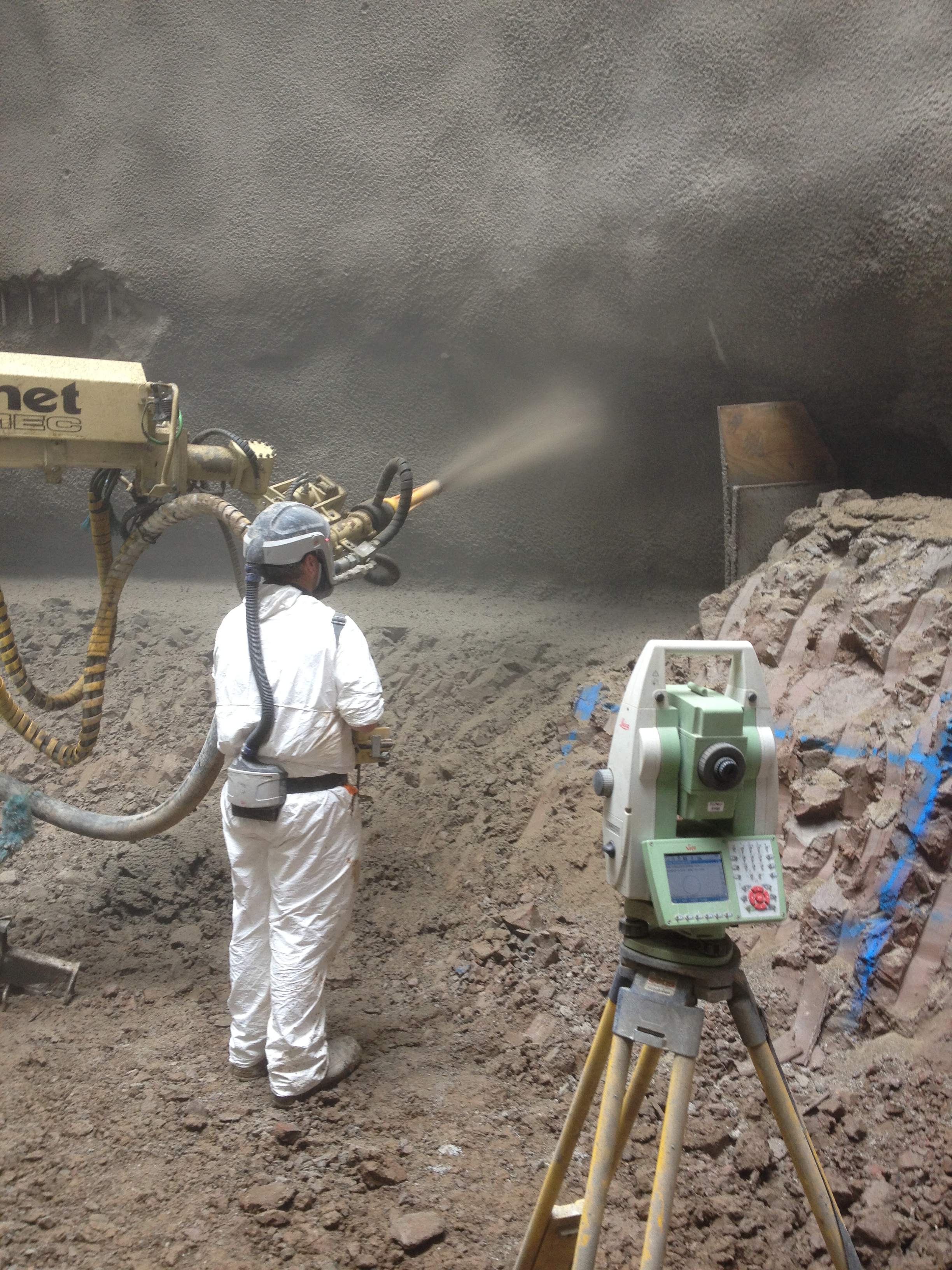
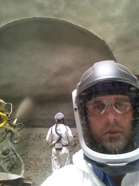
Some of the nozzlemen are the highest paid workers on site, which is quite interesting as the course to qualify is only 5 days long.
Anyway we are getting close to the base slab now and that means that we need to depressuirse the water, to ensure there is no up heave when constructing the slab. We contracted this phase out, essentially constructing 2 x 11m small boreholes in the bottom of the shaft. The photos below show the sub contractors digging the boreholes.
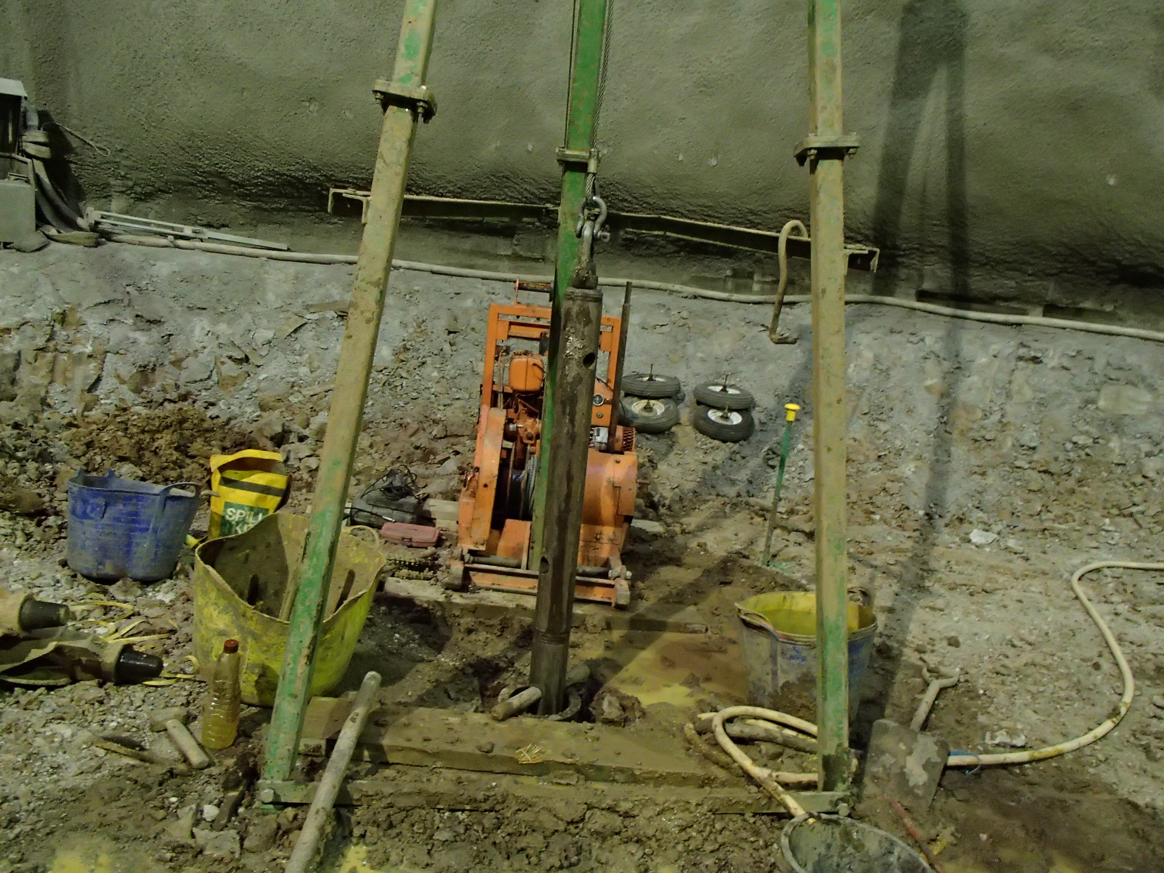
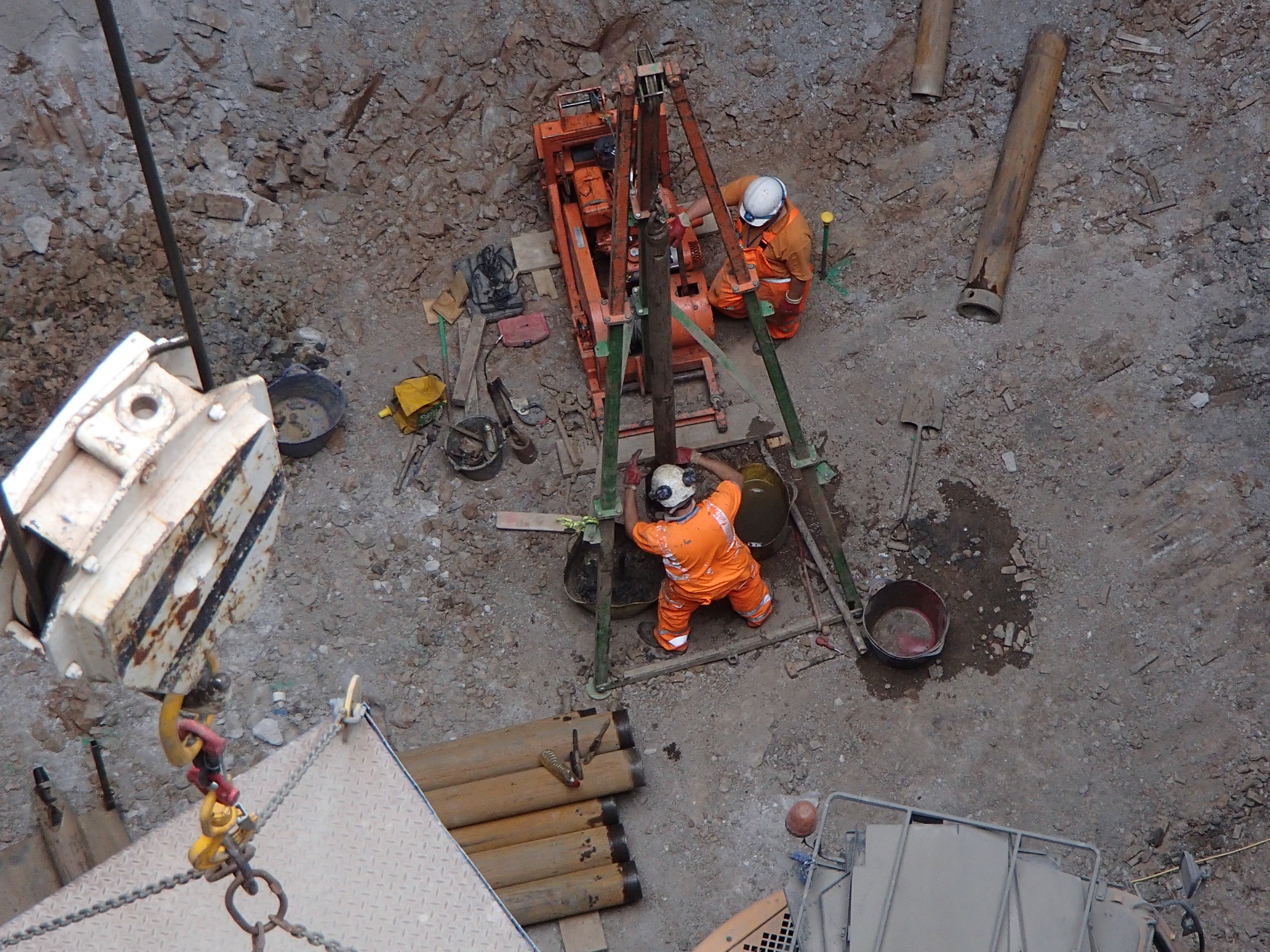
Its a very simple solution to potential up heave of the base slab. The two boreholes will allow the water (although there is no water as we are in the Lambeth clay layer which is more like mudstone) to release the pressure. Theoretically once the base slab has been cast and the slab has gone off, the boreholes will be closed off and the base slab will take the force. However as I said there is no water in sight any where).
I have just attended the Waterproof membrane trials at Bond Street. THis will be the next phase, due in about 1 week. Essentially it is a large roll of waterproof membrane. THis roll will be lowered to the bottom of the shaft and pulled to the top, where it will be nailed in place. Once the membrane is in place the secondary/in situ lining will be constructed. THis is the poured concrete. I have just completed the TW design brief for the shuttering. THe shuttering will need to be able to handle lifts of 2m. THe sub contractors have estimated a 28 day period to complete the in situ lining, I am extremely doubtful but I remain optimistic.
I am currently eyeball deep in a CE (Compensation Event) trying to calculate the time delays caused by out of spec concrete. However my next post will probably be about the CE procedure and the lessons (if any) that I have learnt.
Just managed to book myself on the ICE presentation about the Super Sewer construction in London. Looks like it will be a good talk on the 19th Sept followed shortly afterwards by the ‘Hidden Shafts’ talk on the 02 Oct. Let me know if anyone else is planning on going to either of these events.
