Archive
A problem with BIM
Following on the BIM theme from Rich, I thought I’d share a new concern that has arisen in my office.
I work for the Ports and Martine Division at CH2M, one of two global specialist in large container terminals and large port infrastructure. The benefit of being a huge fish in a small client pool is you pretty much win the jobs you want, over price the jobs you don’t want to make big profit or, if you’re busy developers (sometimes) wait until you have capacity. It also means that you’re able to constantly refine what you’re doing and when a new player appears, you can price them out of the game!
There is a weakness in this armor however…….BIM!!!!
The tender team have received a job brief to prepare a bid for a new container port on the Panama Canal. The tender pack contained some BIM images and design of concepts ideas used to win planning authority for the job. The client (a global shipping company) used a US consultant to support planning approval and to help prepare the tender brief. The problem is that the tender brief contains 3D designs and models produced by my office for another job, for the same client, in the Middle East.
So…anyone that has received that tender brief has CH2Ms design, 3D CAD protocols and material information attributed to the model. Luckily in this case the design assumptions weren’t included as it was an early BIM’d project but who knows what will appear next time. Realistically, it’s now just a matter of time until other companies learn enough from the established players to challenge the market.
We (the military) talk about the security concerns associated with BIM but commercially, money is security. At the moment no one quite knows how to address it but the initial thoughts include strengthen contracts to constrain a design to a project (incredibly hard to implement) or limiting the info that goes into data base and how it is linked to the model (counter intuitive and counterproductive). The reality is that no one here quite knows how to tackle this ever growing problem.
PIANC Study Day
Yesterday I attended a PIANC workshop at the ICE. PIANC is the International Navigation Association, the body that produces codes for ports and waterways and governs much of what I am doing during Ph3. Coincidently, the chairman of PIANC works for CH2M.
The day focused on the ‘future of design’, challenging and refining codes, and expanding design in to new areas such as seismic (previously not covered).
In parts, the technical aspect when straight over my head as I lacked decades of practical experience however, some of the key takeaways for the day were completely generic across design disciplines.
Some generic points:
Updating of codes – M/515 (Extending the scope of Euro Codes)
There was a public acknowledgement that the updating of ENs due was overly complex, poorly publicised and understood. The main concern were the pending changes (M/515) to load factors, partial and combination factors across all areas of design.
Code Bashing
There is a concern that code writers have become wrapped up in code-bashing. For instance, the ψ (trident for Brad) factor, in ENs is used for long term effects such as creep. So why is that factor appearing, in the same context, in codes dealing with seismic design…surely the impact of the ground accelerating back-and-forth is far worse than a little creep. PIANC are attempting to identify these cases and add clarity/remove confusion within their own codes. They are also offering their finding to the EN and BS committee’s but acknowledge that changing principle codes will not be easy.
The legal requirement of codes
ENs use the would Shall which legally implies you must do it. BSs use Should which implies a recommendation but is supported but an understanding that without just reason or better knowledge it should be considered as shall. The bottom line and advice from PIANC was to treat these as the same ‘a legal requirement’ and only challenge the code if you undertake some form of monitoring, statistical or physical modelling during the design phase.
BIM
Not a single engineer present (over 100 from a wide range of companies) had used BIM for any non-government project. Furthermore, when asked to what degree it had been utilised for Gov projects, only sniggering could be heard. There is no doubt that if used correctly BIM is a fantastic data managing tool that would support the H&S/project files etc. However, this is not happening. The key concern is that as-builts are improving but supporting cals, assumptions, etc are not available which makes future alterations difficult. PIANC is attempting to manage this by introducing the requirement to produce a ‘Facilities Operating Manual’. In essence the factors and design assumptions made at every step of design are to be logged and presented with the drawing pack. This is not optional if designing to their codes. It does not require companies to expose their calcs or software details but an understanding of inputs and outputs along with factors.
Summary
The day highlighted a genuine desire across the industry to refine the policies and the codes in use. The senior PIANC committee were open and seemed active to explore ideas being presented to them rather than trying to justify their latest publications. There was a acceptance that the ENs are so vast that using them as a baseline and working alongside was the most proactive way to progress rather than trying to alter, amend or refine them. The day finished with a short discussion on what, if any, new codes should be written.
Genuinely a good day that expended my understanding of how the codes are born, developed and published. It was warming to see that the industry steers the codes and is not simply constrained by them!
Bedding In – Ph3
I’m in my second week working CH2M (previously known as Halcrow) working for the Ports and Maritime Division and suprisinly…I’m enjoying it!!!
I don’t intend to go into any detail in this blog but rather set the scene and prompt questions should anyone have any.
I have joined the Queen Elizabeth Class (QEC) project which is designing the dock that will birth the new aircraft carriers in Portsmouth. DIO are the client and VolkerStevin are the contractor.
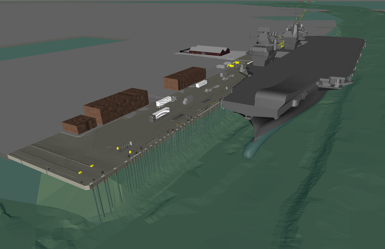
The dock is an existing 19th century sea wall with a 1930s and 1970s series of jetty attached to it. The water depth alongside the jetty is sufficient for the new boats however, the jetty capacity is well below the new requirement.
The key loading on the jetty platform will be :
Vertical – bogie point loads from the mobile cranes. The jetty will also house a new M&E shed that will house all of the ‘wizards boxes’ used to generate the electrical feed required for recharge (these are pretty big and heavy). Finally, the jetty will be expected to support lorries and container stacks all over the place.
Lateral – the boat hitting the dock when it parks (technical term), 100tn.
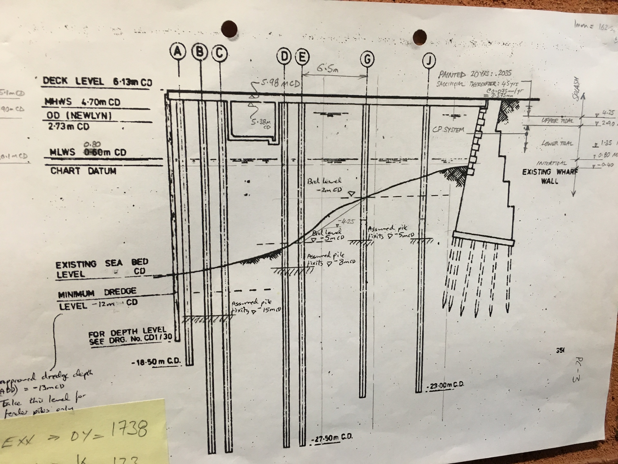
The plan
– Two large section of the jetty deck will be demolished and rebuilt.
– One strip of the deck will be cut out to allow new piles to be threaded through the existing.
– A number of holes will be cut out to allow new piles to be fed through, many racked to facilitate the lateral loads.
– 2m concrete deep beams will be inserted under the deck across the top of the new piles.
– Pre-cast slabs will fill the holes.
– A new deck will be cast in-situ to thicken the whole deck with a single in-land crossfall.

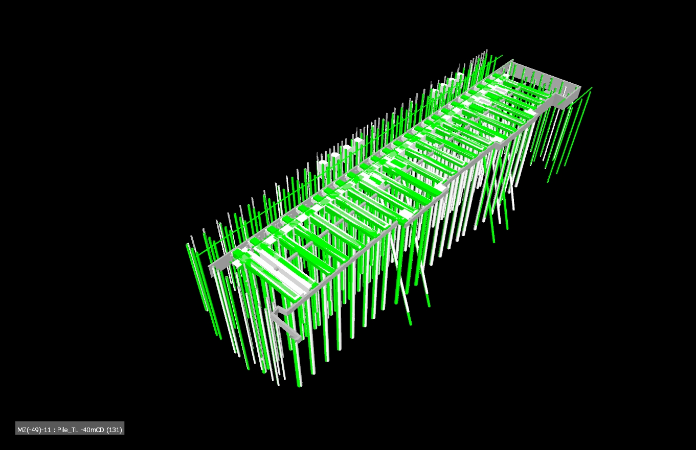
Grey is existing, green is new
ICE CPR
Two of my identified weaknesses when moving to Ph3 were technical design/analysis and working with existing structures. I think this project will serve me well!
Remove the reins
My first job has been to conduct a shear check between the existing and the new decks where the mooring bollards are located. The bollard rating is sufficient and the bolting down design has been verified but it was unknown whether the deck would simply rip apart. EN 1992-1 has a section on concrete poured at different times so that became my starting block however, it assumes the shear failure would occur due to bending so attempts to use the lever arm from the bottom steal to the shear plane (it assumes you are looking at a composite beam and slab arrangement). I knew this made no sense and after a long time (a very, very , very long time) I realised what the problem was and substituted to for F/A. The rest became code bashing exercise of mumble jumble Greek. The key take for me is that I knew it wasn’t right and knew where to go to sort it out. That may sound like a small thing but the kudos of presenting output without direction on my first tasks seems to have served me well and boosted my confidence for the next six months!……….Who’d a thunk I could produce a calc with Damo’s help 🙂
In other news
My office has the design contract for the Middle East Basing (think Op Shader). I was asked to look at a deployment order to send some CH2M Engrs out for technical design support to delivery. Page two of the doc had the CoC outlined and OC STRE sat at the top of the tree…like a slap in the face I was reminded of my day job after this process ends.
Site Diary
When I arrived on Ph2 I was given four options for maintaining a site diary:
- The official BAM form (Not very user friendly and requires printing and binding)
- A home made excel spread sheet (designed for a different job)
- iPad Field 360 (the consensus from our site is that it is a v.poor piece of software that requires a great deal of time and investment)
- A blank note pad!
I have tried all of these and can conclude the classic note pad won for its ease and ability to go anywhere!!!
However…maybe technology has finally turned up trumps.
Our GF has been using an App on his phone called ‘Day One’. Its a daily diary app that allows you to tag photos, write text, etc but auto links a location, time, weather…. Furthermore, it allows you to search for events with far more ease than the other IT options in use with BAM. All events can be shared with ease or exported as pdfs.
I have use it now for a few weeks and it has increased the level of detail I have recorded as well as drastically reducing the time and effort involved to stay up to date. The only negative I can identify is the risk of using mobiles on site which must be managed accordingly, dependant on your site.

Diary overview with thumbnails and titles.

Annotated photo with auto linked information
In my opinion it’s a tick VG for Day One and certainly something for the Ph1s to consider if they are not constrained to company policy.
Adding water to concrete on site!
I have mention this in an earlier blog however, Richard asked me to highlight this again as he’s currently delivering the concrete package.
The practice of adding water to a concrete mix in order to brings it’s slumps back inside tolerance is poor at best. It alters the water/cement ratios and affects the whole mix, however, we are allowed to add water on site!
The concrete specified for our bridge is a C40/50, 20mm limestone mix. The limestone aids with the strength but also assists with ensuring that no chlorides are in the concrete which would cause long term PT tendon corrosion issues.
The problem is that limestone draws moisture out of the mix at a hell of a rate and during the trials we had real issues in maintaining a workable mix. Plasticisers and retarders have been added but altering a mix is not as simple as adding more….
As a result, the supplier monitors the mix, travel time and ambient temp and provides a certificate that details how much water we can add to each load. Every load that arrives is different and ranged from 0 to 72 litres (the most I’ve seen to date). Very rarely do we have to add this, normally the slumps are within tolerance but when loads get held up or arrive marginally out of spec, it has allowed us to keep batches alive.
Today’s pour should have had a 180mm +/-20mm slump but one load was measured at 130mm. The ticket specified up to 33l could be added. I added 10l to a 6m wagon which brought the slump up to 190mm, a little water makes a big difference.
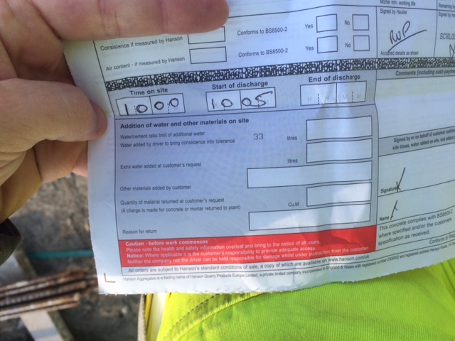
Concrete ticket – max additional water is marked on every ticket

Water gauge – For QA we have to monitor how much water is added.
A Near Miss
Part of our falsework system incorporates 7No, 21tn, 30m trusses. These are assemble on the ground and lifted into place.
On Tuesday one of these trusses fell over during construction and landed at the feet of one of the lads. The panel that fell weighs 380kg. This is the sixth truss built on site, no previous concerns had been raised.
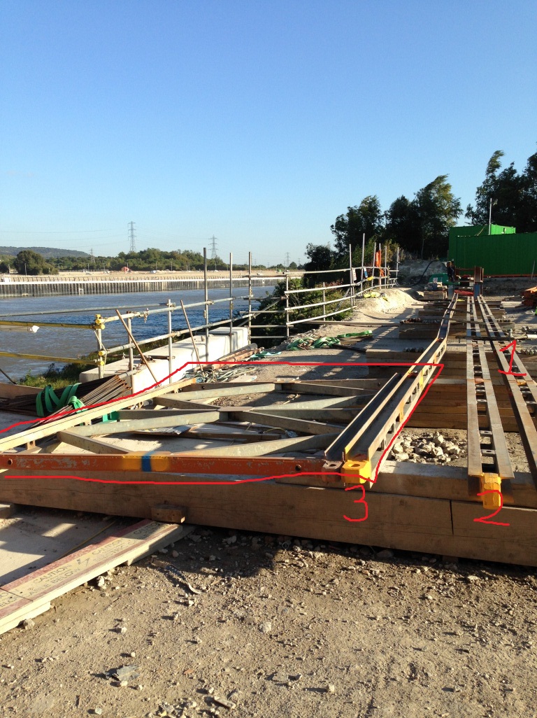
The highlighted panel was vertical. Bottom cords 1 & 2 are in the correct position, 3 has rotated with the panel. This panel had no lateral bracing.
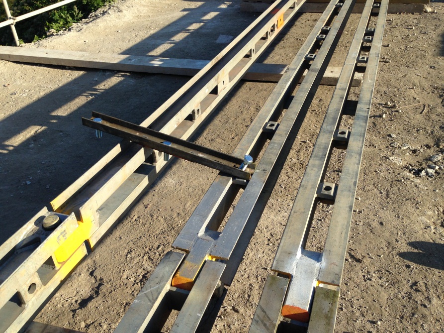
The cross bracing has pulled out of it’s alignment. NB, this was not bolted as the cords are left free to creep through construction. The construction method was instructed by the supplier.
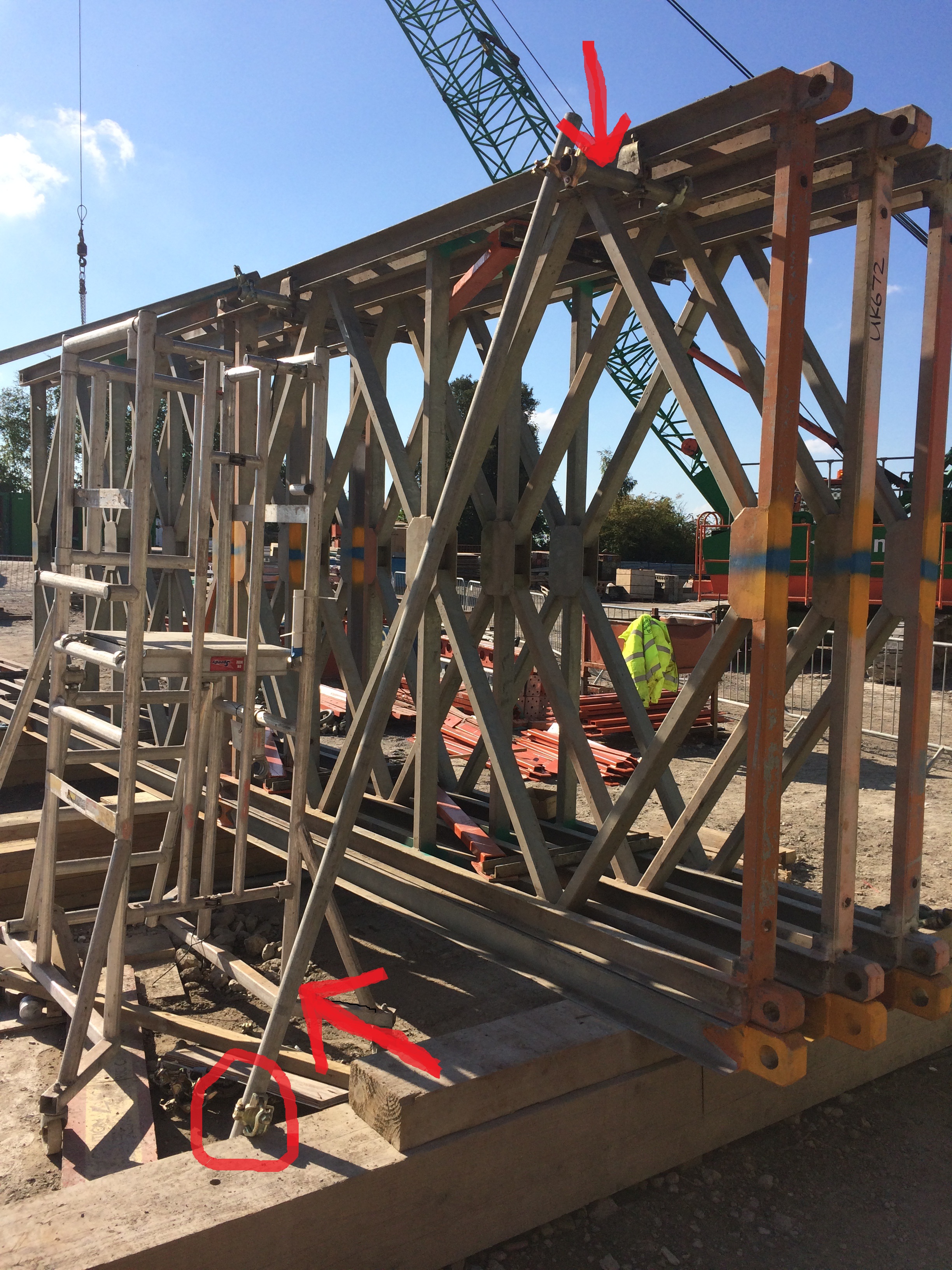
The revised construction method includes ‘tube and fit’ bracing.

The bracing is also tied back to the hand rail which has been increase to deal with greater loads.
Installation of these trusses sits on the crit path so no time was wasted in assessing, reviewing and modifying the construction. This process was thorough and the new mitigations seem to be appropriate and full proof with regards to a repeat of this situation.
A happy truss!!!
A link for the E&Ms (Fran, you should suggest this for your hospital!!!)
Words not required!
Damo has been texting me, so words are required…
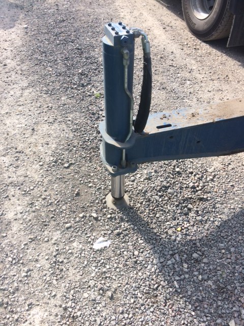
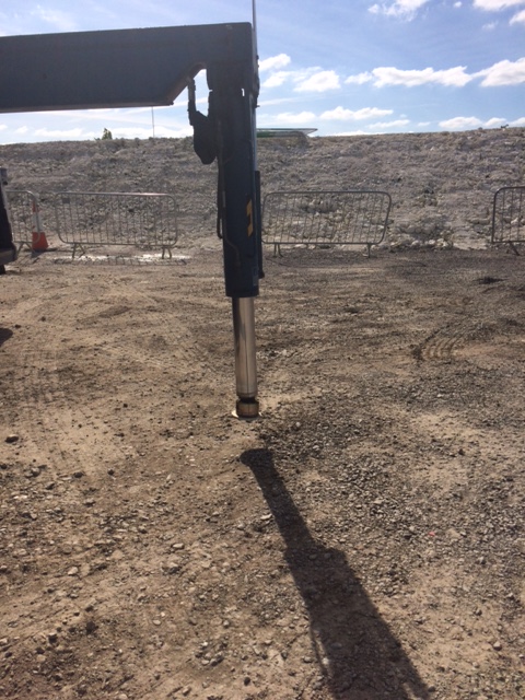
These are outriggers on the side of a lorry. I walked out of the office to find the truck like this, the driver said he hadn’t noticed but thought the ground was fine.
Before you ask, the pads were neatly stored behind the cab where the driver keeps them safe, warm and clean!
And as i’ve just replied to Damo, no calcs were required to work out the ground wouldn’t hold, a simple heel test would have told anyone that (not to mention the car park rutting about 6ft away which I should have taken a pic of, doh)!
The Good
The Bad

The Down Right Ugly!!!!
Total Deadlock!!!
Just before my summer leave I attended the most frustrating meeting I think I will ever endure…it made a TFH ISTAR planning co-ord appear proactive!
The background
The embankment that approaches each bridge abutment has a series of piles called CMCs (Continuous Modulus Columns). These piles are placed on a 1m grid over the width of the road for around 50m. They do a number of things but mainly they stiffen the embankment material as they are displacment concrete piles and secondly they transfer some of the load through the constructed embankment to the stiff clay below. They contain no ReBar and are designed to fail if heavily overloaded.
The Problem
Given that the CMCs are not reinforced, they are designed to work in a specific way. Any structural movement will eat in to the tolerance of the CMCs, this means that it would be crazy to install the CMCs whilst our site is still undergoing large amount of settlement we’re still experiencing. Whilst the settlement is starting to slow it has not reduced to the level the Vibro Minard, the subby that is installing them has specified.
The Sticking Point
- Vibro will not give a warranty on the potential for differential settlement of the installation until the ground is at the strength originally specified.
- WSP, the designer, will not check the original spec or conduct any alteration without a FULL check of the whole scheme (big £££). Clearly they can see we’re over a barrel and know something has to give. Their argument is that a reduction in platform strength may have a fundamental impact elsewhere and that requires checking.
- We only have a six week window to get this done before it takes over as the critical path and causes programme delays.
- Kent Council are unlikely to accept the embankment without warranty (we don’t want to ask the question as it will likely open up a huge amount of questions and interest).
- We don’t have the budget to cover the warranty as the project is heavily in debt and this sort of warranty would be for an unknown sum given that no one internally really understands the actual design enough to predict what may happen.
We left the meeting looking at each other saying ‘so what now’.
So What
Quite simply we’re having to wait for the ground to ‘Get A Grip’ and toughen up.
We’ve conducted a number of onsite tests to check the current strength in the ground. The good news is that it’s higher than we expected based on the original model and pizo data however it’s not quite as high as we need.
We have asked the designer look over the findings a predict what the ground strength will be by the time Vibro mobilise if we give them the thumbs up now. It’s looking good, so fingers crossed.
The Disappointment
The sad thing was, everyone sat around that table knew how to solve the problem but hid behind lines like ‘this is what my design manager has said…’! Whilst I understand the requirement to make money, I will never understand the mentality that it is ok to do so whilst others fail, sink and lose out. What made it worse was the lack of spine demonstrated, if you’re going to represent your company then embrace the policies they set, don’t hide behind people who are not present in an attempt to deflect the criticism away from yourself.
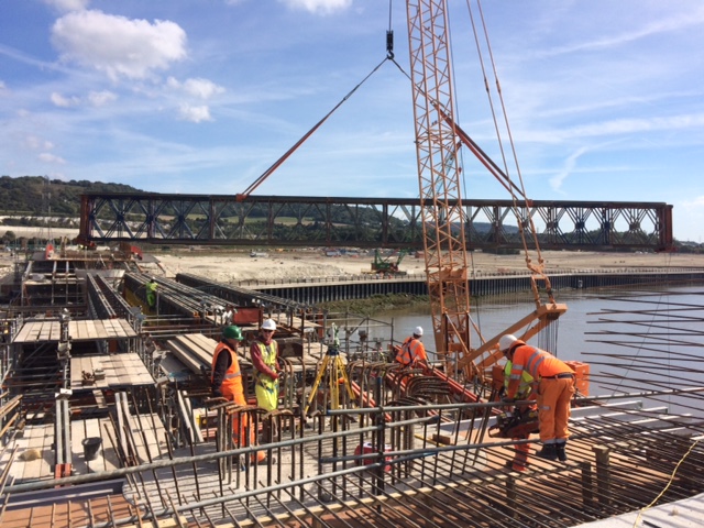
The Good News
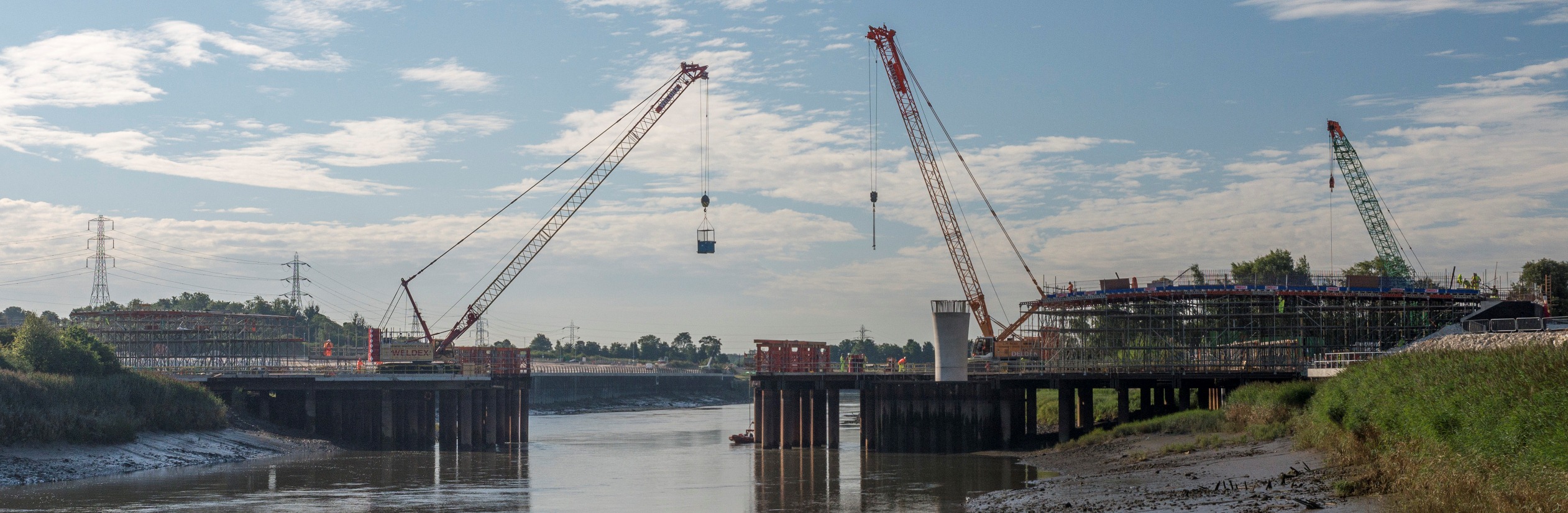
We have a structure that is starting to look like a bridge, peirs and all!
A Novated Contract
My project was originally run to tender in 2007 but our bid fell short. When the economy did a summersault the project was shelved. In 2014 it was revived however our new bid was also declined and most of the tender work was thrown away. Within a matter of weeks BamNuttall were asked to resubmit it’s tender as T&Cs had not been agreed with the 2014 contract winner and the they had pulled out…cue alarm bells!
The revised 2014 quote was c.£400k lower than the initial 2014 quote. It was accepted pending two key conditions:
- A team would be mobilised with immediate effect and begin work (this took a week). This was necessary to comply with planning conditions outlined by the local authorities.
- The original designer who designed most (not the river bridge) of the 2007 scheme would be novated to us under a D&B contract but they would now become the sole designer for the whole scheme and adopt the original river bridge design from Halcrow.
Novated – I had to look it up but in effect it means that you take on the asset under the original T&Cs.
The Problems…
- The original river bridge was designed by Halcrow. The designs were handed to WSP but none of the supporting calcs, therefore WSP had to pretty much redesign the whole bridge prior to an external CAT3 check. This was not costed in the tender. It also lead to lengthy discussion as to whether WSP accepted the risk when agreeing to adopt the bridge design or whether they were explicit in outlining the cost associated with a redesign.
- TrentPort (Client) use JCT contract for all of their other project. This was already in place with WSP when our bid was finally accepted. We have entered into a D&B NEC3 contract with the client however; we have taken over the JCT contract with the designer. This means that when we all sit around the table we are not contractually talking the same language.
- Value Engineering benefits the designer. Within the NEC3 contact we have detailed that any value engineering change will benefit us 75% and the client 25%. If this is a method change then no VI is required however if a VI is required then the designer will be paid and the profit reduce prior to the split. However, because the designer is in a different contract he has tied our hands on numerous issues and we have been forced to pay hand over fist to move the most simply checks and tweaks through.
The Sticking Point…
The relationship with WSP is frosty to say the least. The designer working on our project is a nice guy who appear rather uncomfortable at meetings when he’s asked to comment or make quick amendment. He simply speaks on behalf of his master and repeats ‘please formally request the RFI or design change, we’ll quote you for the work and then you must instruct us to carry it out’. As you can imagine this is a long, slow and frustrating process which often takes weeks for tweaks!
The Solution…
We continue to press on often building at risk or making quick changes to the programme to re-order the construction sequence whilst we wait for answers.
A meeting has taken place between our commercial team, our design co-ord and WSP. Some form of payment (details are unknown) has been agreed in order to speed up VIs, RFIs, TQs. Over the last couple of weeks there has been a marked improvement however the it feels like a triangular mine field where no one is willing to step in to the middle but would rather tiptoe around the edge and waste time and money.
SWOT
Guz hit the nail on the head when he mentioned the use of a SWOT analysis or lack thereof. The speed that this project was established was rapid, I spoke to Steve Payne a couple of weeks ago and he was shocked at how quickly things had moved. It appear that the focus was very much on the ‘O’ with a little ‘S’ thrown in for good measure but I’m not sure a great deal of time and effort was invested in to the ‘W and T’.
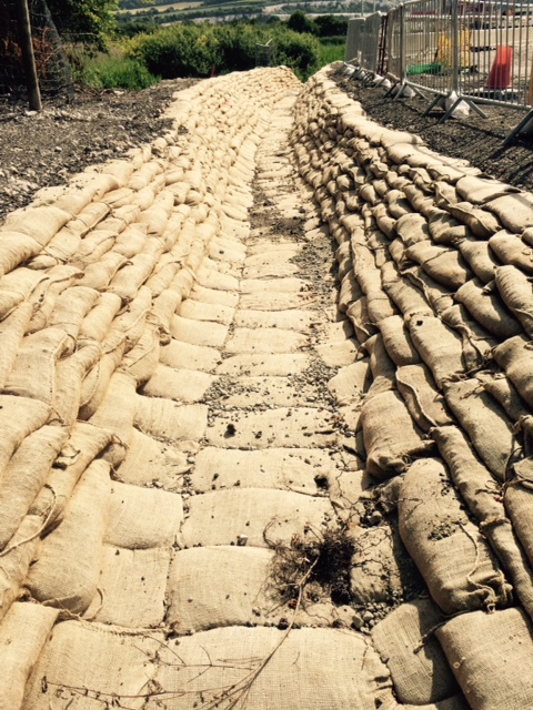
On a Lighter Note…Check out this sandbagging!

Concrete – Follow up to the discussion on Damo’s Blog
Richard, All,
This blog is in response to a conversation on Damo’s last feed.
Here are some photos as requested. I must add that although this abutment will be black jacked (bitumen cover) and buried it was intended to look exactly like the finished bridge…we have some work to do!
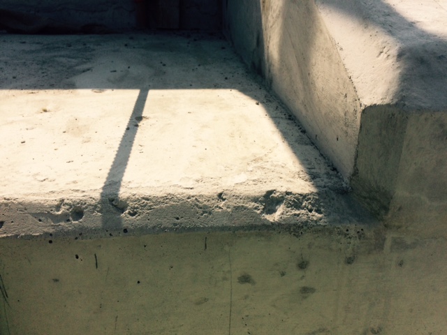
The kicker should simply look like a line joint
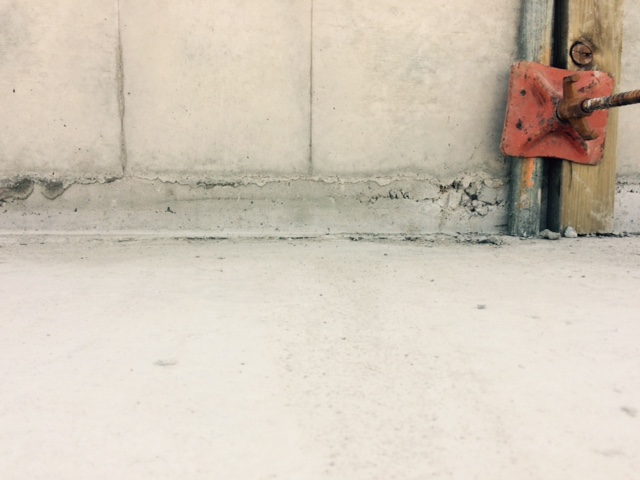
The wing wall has had to be built up. This will not have the durability it should. If you look closely you can see aggregate viable on the top face.


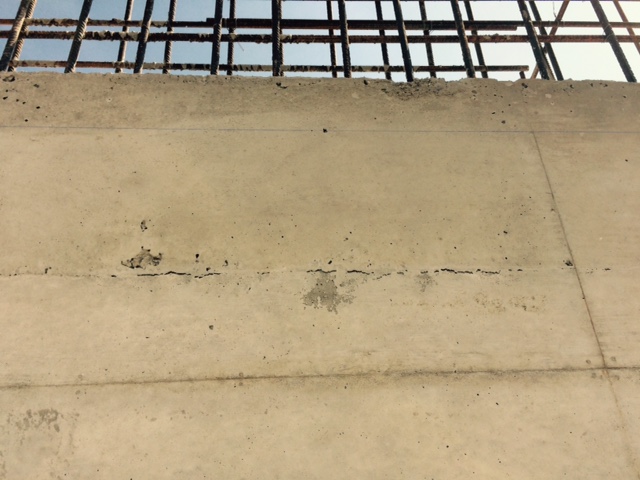

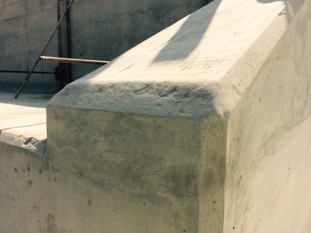
Staining, we’re not sure why…has anyone had anything similar? I am conducting trails in a couple of weeks to try out different formwork materials
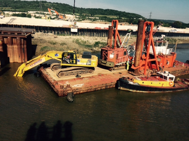
In other news, we hit an obstruction in the river and had to bring in a spud barge with 45tn machine. It proved to be a great spectator sport but not much work was done on site whilst it was here.