Archive
BBC News Hyperlink
An interesting approach,
http://www.bbc.co.uk/news/resources/idt-3cca82c0-af80-4c3a-8a79-84fda5015115
Pile Collapse
The west abutment piles (8No, 900mm dia, 40m deep) are now complete and passed the working load test with ease. We are now in the process of blinding the area to create a working platform prior to integrity testing the piles tomorrow.
West Abutment Pile Test
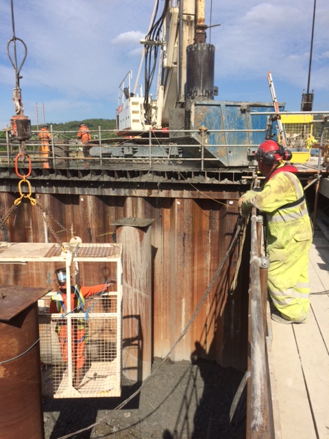
The west cofferdam is complete. The excavation turned out to be more complex than we anticipated and caused numerous problems. Eventually we managed to dig to depth and blind without having to fit the intended lower waling. The top of the sheet pile walls have been capped and a UB panel roof has been fitted. The 80tn piling rig now sits on top of this and bores through the open cofferdam and into the ground below. A piling case gate has been fabricated to stabilise the case above ground level and help locate it whilst being lowered.
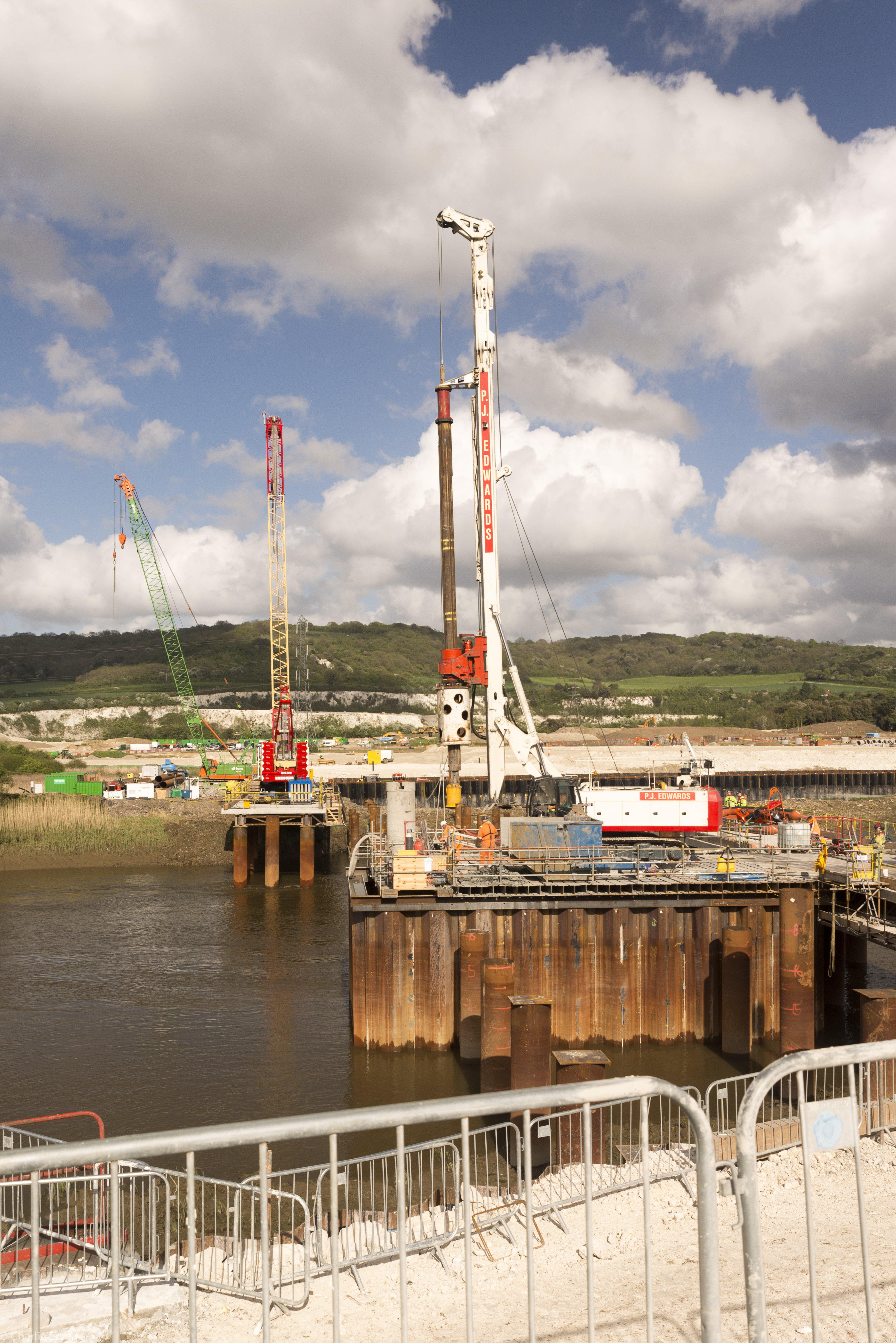
80tn Rig on Cofferdam. This is the most unusual place the Piling Foreman has piled in 30 years
Piling gate and pile casing.
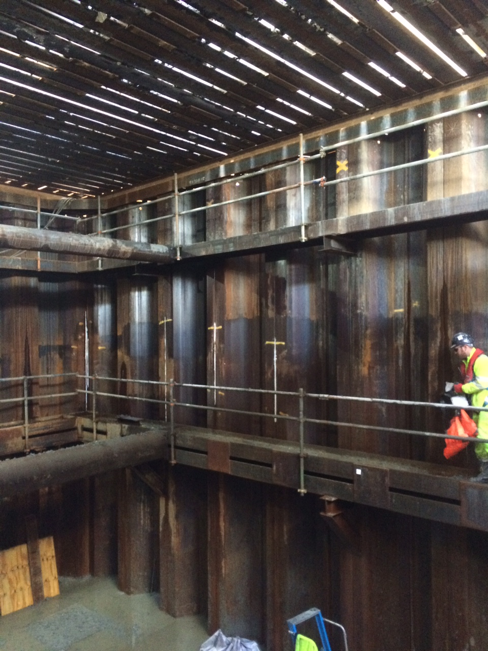
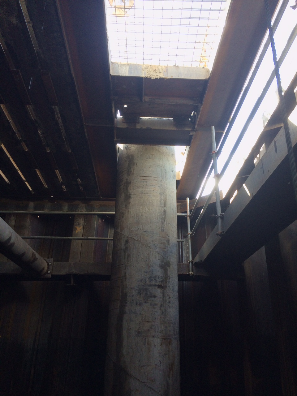
Inside the west dam with the rig above.
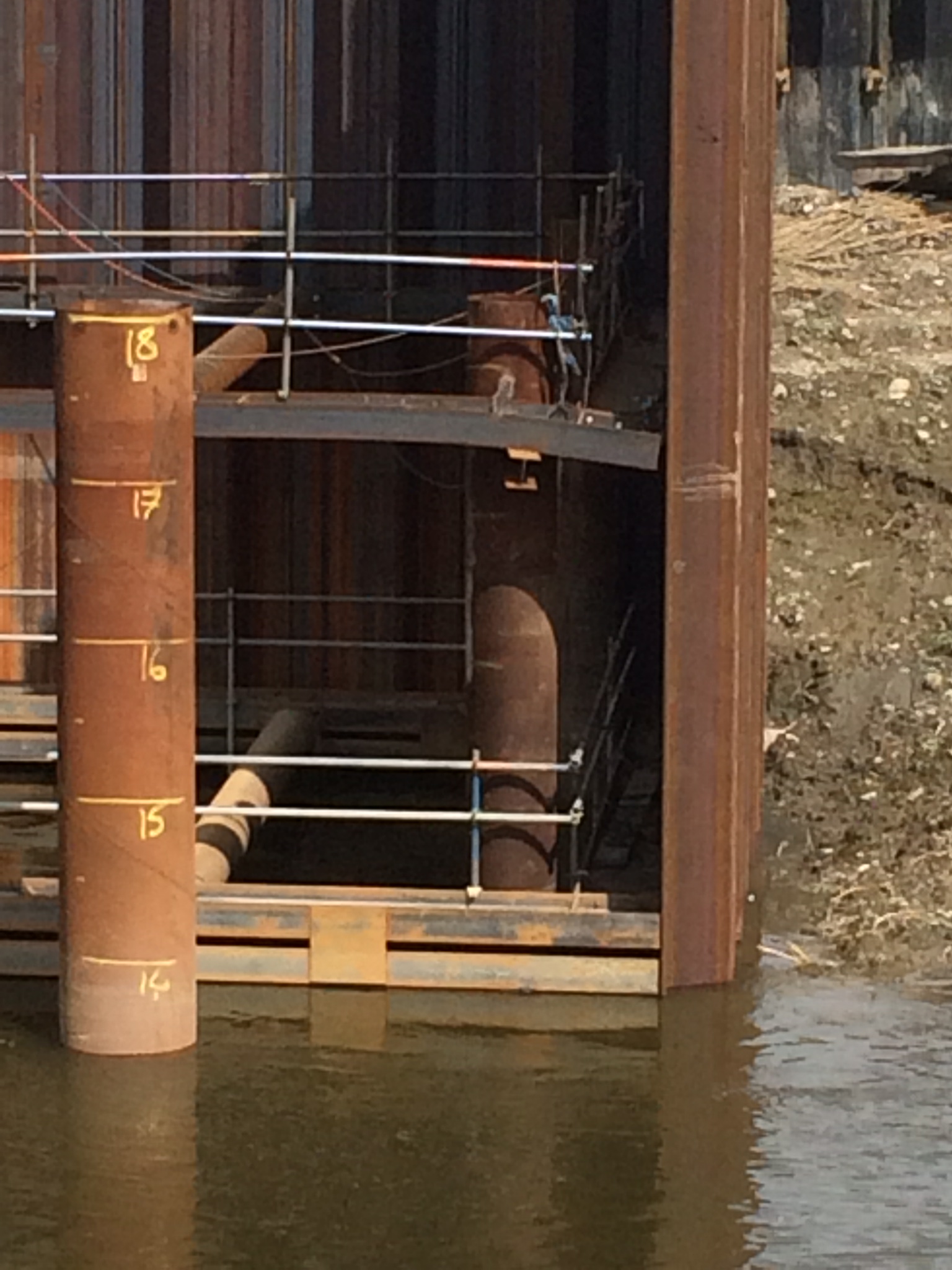
The casing starts 1m above the deck and drops 8m through open space and a further 5m into the ground of which 3m is toed into dense clay. The first problem this throws up is that the pilers can’t see the ground level down the shaft, to resolve this issue they have cut a window in the casing above ground level that they can look through from the base of the cofferdam. This window also acts as a water escape when the concrete is being poured allowing us to capture the spill in the dam. It also allows us to monitor the concrete to ensure we are not over filling and creating a large mess (7m3) when the case is pulled.
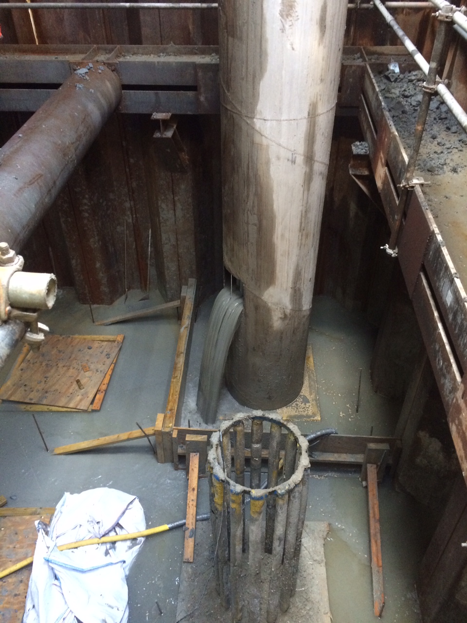
Pile casing with window during a pour. Excess concrete is kept within the simple shutter and cleared up by hand 12 hours after a pour.
Working on top of the cofferdam has caused a few logistical problems, there is no space to store any equipment and the spoil has to be spun off in to a skip and then craned on to the land which slows the whole operation.
Bore spoil is spun in to a tipper skip. Note this is not an accurate process and we lose some over the edge which has to be recovered.
All has been going well and we are completing them at a rate of one a day, until…TODAY!
The piling gang are on a fixed price contract and are clearly keen to get the job done and move on. They asked last week whether they could auger out at the end of a day and then concrete the following morning. This is outside of the 12 hours that is permitted to leave a bore open. On Tuesday approval was granted that this could be done under strict rules:
- 12-24 hrs open – increase the depth and cage length 1m
- 24-36 hrs open – increase the depth and cage length 2m
- 36-48 hrs open – increase the depth and cage length 6m
These rules were issued by the piling designer and based on 10% reduction in shaft resistance per 12 hours. When question on the 10% reduction they simply responded with ‘it’s over designed to negate any risk’. This makes perfect sense, as any decision to leave a bore open would be with the piling contractor and as such any increased cost in materials, time and risk would all sit with him, not us or the designer.
That same day (Tuesday) the rig broke down just after they have reached full depth. By the time the rig was fixed (Wednesday) and it had got back on task, cleaned out the shaft and augured out the extra 1m (rule 1) they had missed the concrete window and had to leave the shaft open again overnight.
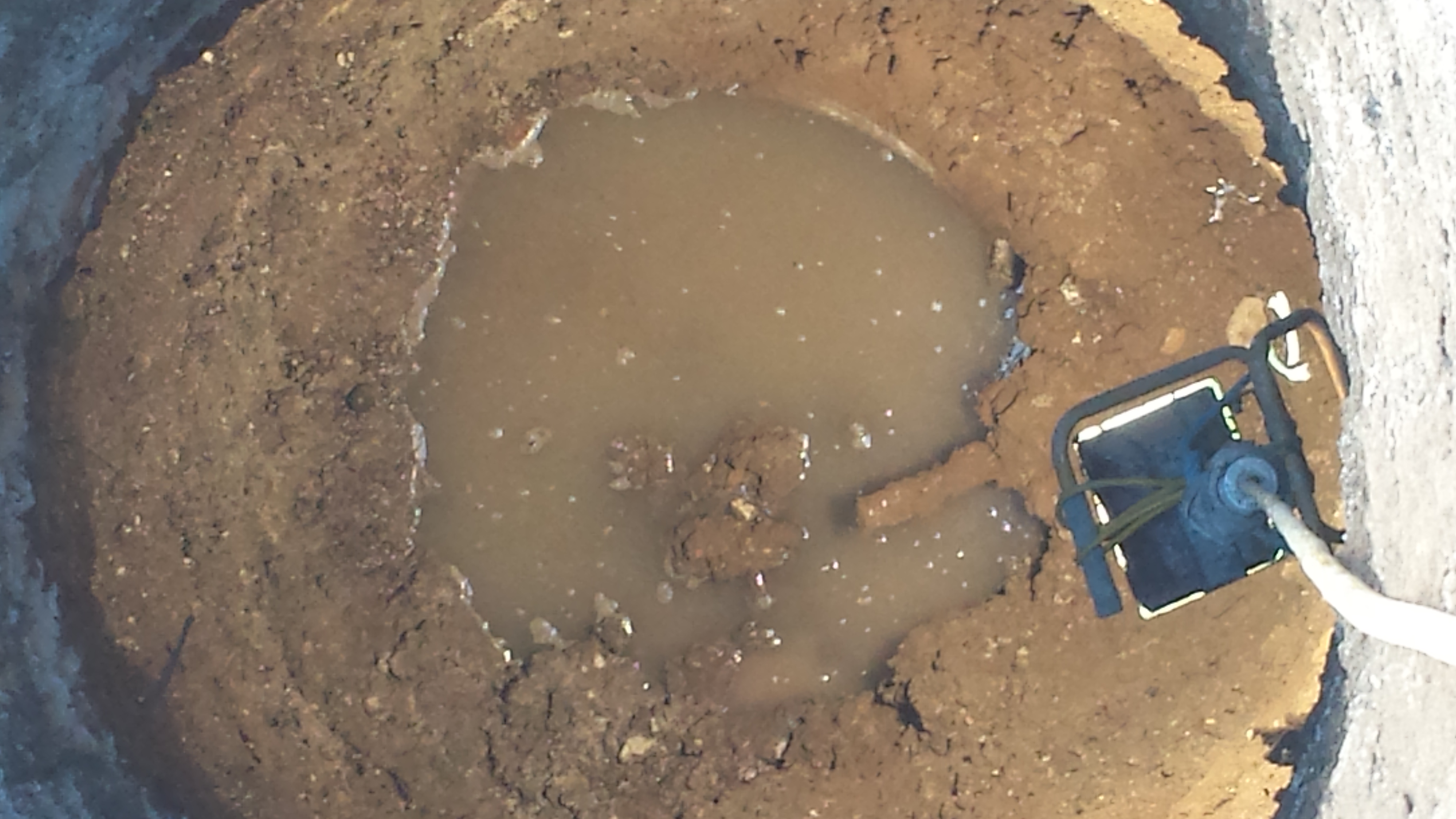
When they came in this morning (Thursday) they found that the 43m shaft was now only c.20m. Due to the casing they are unable to see what has collapsed. We are currently pumping 10kN concrete in to a hole with no real idea where it is going or how much of it we will need to cap it off.
So what…
We must now treat that area as unstable and move the piling operation to the other side of the cofferdam and work back towards it. The pile designer has been briefed and will now carry out a redesign of the failed pile. We expect them to either design a number of smaller piles to be placed around the failed one or to insist we re-auger in the same location though the low strength concrete. We are unsure how wide the collapse area is and whether it has affected the existing piles or fresh ground that we are due to pile through in the coming days. Either way the replacement pile/piles will require full casing to depth which will increase the duration of the job.
In other news…
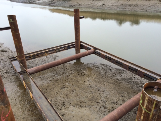
we bent a waling!!!
Sheet pile was stood unslung in 3m of alluvium which has a Cu of about -15!!! When the vibro was lowered on it pushed the pile which sank immediately and dragged the waling with it!
BIM continued – FAIL
As previously mentioned our BIM set-up is more targeted at data collection than actual collaborative working and as a result we lack many of the real benefits BIM has to offer.
Our river wall consists of a 16m deep sheet pile wall that is paralleled by a 6m anchor wall. The two are tied together by 63.5mm bars (dwg below). This was installed a couple of months ago.
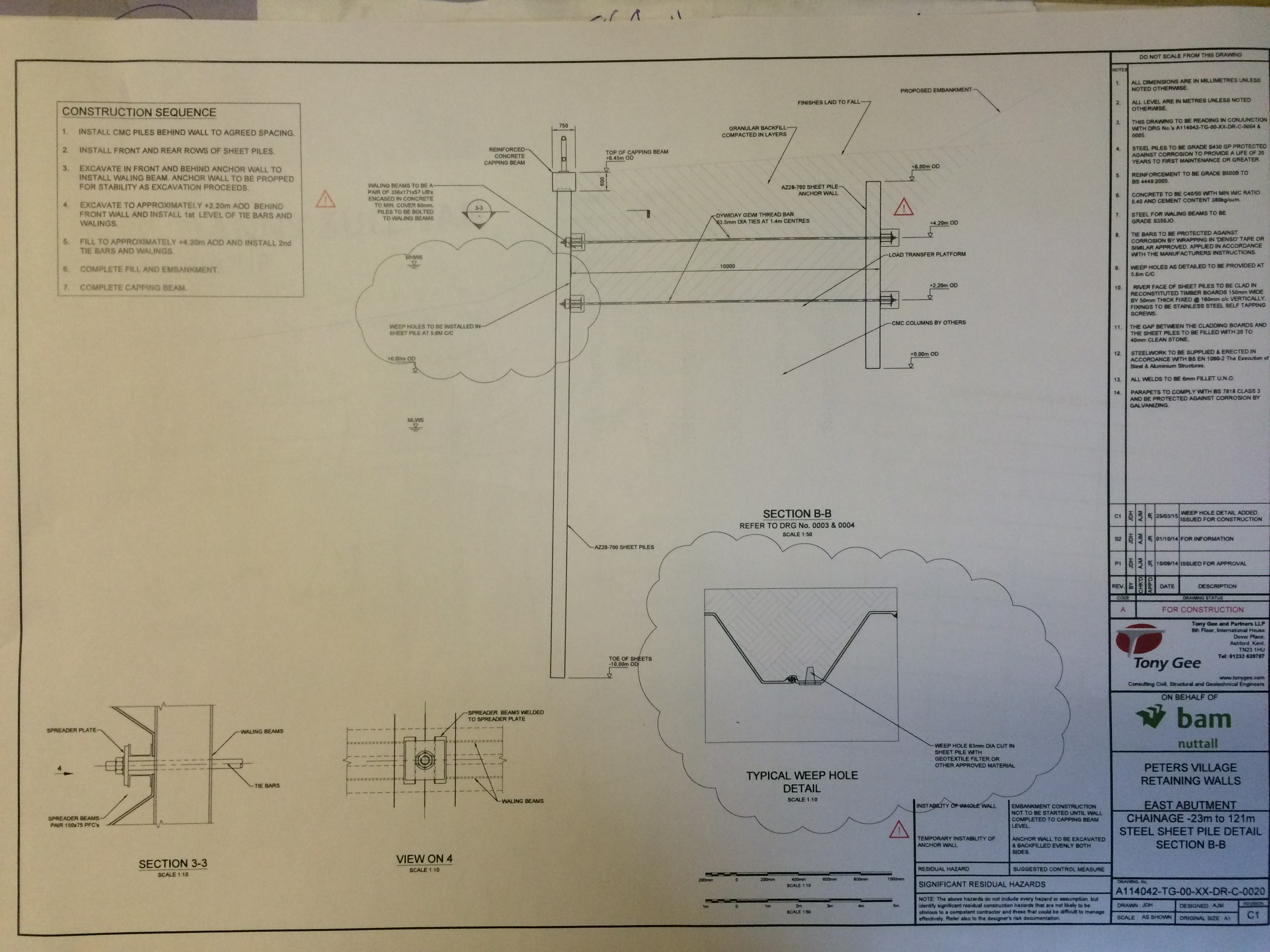
River and anchor wall design
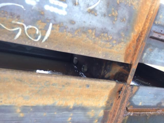
Yesterday our piling contractor hit one of the tie rod sticking out of the back of the anchor wall.
6m deep, tie rod visible on the left of next to the light.
The sheet wall and piling scheme designers are different and neither of these are our principal designer. We are now in the process of getting the pile location redesigned. Hopefully the designer confirms the coordinate change in a couple of days otherwise the piling gang will be stood at a cost of £6k/day. Whilst I’m not going to get in to the specific details it is fair to say that collaborative working would have gone a long way to prevent this form happening.
So…
What is the better approach, setting up an expensive system and enforcing it or paying to fix problems when they arise?
BIM – Bureaucracy or Beneficial
There is no public investment into the Peters Village project and the last time I checked it was not 2016, therefore we are not at liberty to conform to any governmental BIM direction. That being said we are aspiring to collate all of the project data centrally and utilise technology to increase efficiency at an engineering and management level.
So is it working?
The Good – We have a BIM co-ordinator, a cloud based server, lots of drawings and 3D models. We have iPads with more auto-syncd forms than you would ever need and the ability to capture any media file type and link it to technical information. There is a data base that allows you to see (with permission) the commercial files, drawings, specifications, programmes, plant and materials lists on your phone if you so desire.
The Bad – The engineering check list and QA forms are on Autodesk BIM 306 on the ipads but the filing system is overly complex. The cloud based system is different to BIM 360. We have multiple designers who are using different CAD co-ords so dwgs need aligning. The designers are mostly sending through drawings in pdf format and not as part of a master CAD dwg. The cloud based servers is provided through a satellite link on the East Site compound and boosted over the river (very unstable). Whilst the cloud based system allows access anywhere, the system to upload and download files reminds me of the pain I went through trying to submit AER1. On and on…
The Ugly…Truth – The aspiration is commendable, one central log of information, accessible by all, from anywhere, anytime. The reality is multiple databases holding vast quantities of unrefined information. This is not as a result of lack of ambition but rather lack of training, man power and strategy. Those driving BIM are double hatted and unable to dedicate themselves to it, also they seem to lack the full support of the wider workforce.
BIM carries a high price tag and requires considerable effort to establish the required processes. Early set up and buy in are key, without them the whole process becomes a clunky digital filing system with increased vulnerabilities and lacks the ability to assist with increasing efficiencies. I find myself wondering if the system we have in place has actually brought about improvements of if it has over complicated things.
Just Give It Time
Last week work started on the east bank crane jetty. The ITP requires that the first four piles are to be tested to ensure they will resist working loads. The working load per pile is 2000kN and FOS of 1.5, therefore each pile is required to resist 3000kN (or so we thought, I’ll come back to that later).
The west crane jetty piles were 18m CHS. The east crane jetty piles are the same tubes however they are 20m in length. The east side of the river has a thicker top layer of alluvial deposits and a thiner layer of terrace gravel which provide a lower shaft resistance through the first 9m than the west side. Below this level is Gault Clay which carries most of the load hence the requirement for a longer pile on the east.
The piling gang were ready to start but the 20m piles hadn’t arrived, direction was given to use some 18m ones we had on site. This decision was based on the fact that the edge of the river is higher and therefore more of the pile would be supported. In reality all the piling gang did was hide steel under some alluvial soup that offered no support.
Once the first four piles were within approximately 600mm of their level a Dynamic Pile Test (DPT) was instructed. This consisted of two sensors being rigged to the pile (see below), the smaller sensor is an accelerometer and the larger a strain gauge. Once set up the pile is then driven further by the hammer. The pile dimensions and the hammer speciation are input into a Pile Driving Analysis (PDA) terminal which then records the results from the sensors whilst being driven. This then produces a window of pile resistance. Our first pile registered between 2700-2800kN, not the required 3000kN furthermore we only had 300mm of pile left before we hit our level.

The technician recommended that we should stop at this point and continue the test the following day. The next day the test was then carried out again on the first pile and it reached 2980kN…accepted! The three remaining piles also passed.
Cue Terzaghi and Mohr-Coulomb
When the pile was driven is caused the pore water pressure to rise. This created a hydraulic gradient. With the gravel the short and long term states are the same however in the Gault Clay they are not. The clay has a very low permeability so on face value I wouldn’t have expected much change overnight however the borehole data from the GI identifies veins of coarse sand and gravel with in the clay and also irregular fissures (although it is hard to know if these were caused by the boring process). The reduction in pore water pressure increases the effective stress and ultimately increases the strength of the clay.
These ‘Case Data’ results were then sent back to the office and run through CAPWAP software. This is a post processing tool that analyses the data from the PDA and refines the results with data from modelling and empirical evidence. The technician suggested we should expect upto a 10% increase in the capacity.
The Game Changer
This whole issue is now almost irrelevant; when the designer was called he informed us that the working loads were only 1000kN per pile so we only required 1500kN. This should have been blindingly obvious. The piles work in pairs and support simply supported beams. So four pile support the 110T crane, its load and the self-weight of the jetty deck. Based on the initial 2000kN per pile that would be in the region of a total load around 800 tons and alarm bells should have started ringing at this stage but everyone just got on and tried to achieve the results required without question.
I’m sure I’ve been told a few times to take a step back, look at the fundamentals and question the obvious before getting too involved……phuf, what did they know!
In other News
Guz – I can now join the ‘what’s the best thing you’ve found in your 6F2/5’ game. Today I found some super squishy foam, a glove and what looked like action mans left arm!
Not a calc sheet in sight
Here are a selection of some of the issues that have arisen over the last week,
1 – My spanner doesn’t fit – The standard ‘you must be able to construct what you design’ comes to the forefront with my first point. The fabricators constructed the middle waling for the cofferdam, which consists of double UB’s welded together with plates. The problem is that the ends are bolted together and someone decided it was a great idea to position bolts inside of the facing web openings (see photo below).
Solution – Ignore the bolts and weld instead.
Cofferdam middle waling
Close-up of restricted bolts
2 – Answers on a postcard please – Our sheet and CHS piling gang have done a good job, however, they are really starting to drag their heels. The commercial team who draw up the contracts have dropped a clanger and employed them on an hourly rate, which has been fine up until the last couple of weeks. They are now well aware of the last safe moment for the cofferdam to be finished and are doing everything possible to ensure they don’t finish a minute sooner. The question now is how do you speed up someone who has the upper hand and technically isn’t doing anything wrong, frankly neither the carrot nor the stick will work this time!
Solution – …?
3 – The chalk turned to toothpaste – The majority of the fill being brought to site is chalk. This is causing no end of issue given the current weather. If it’s in a dry-ish state and well compacted it forms a sound and stable base for the abutments and road surface to be built on, however, it is not so dry at the moment and yet we are continuing to receive 600 tonnes a day. The lads were told to stockpile it so that it could be distributed at a later date in the 200mm layers with 4 passes from a 3.75 tonne vibrating roller as per MCHW. BUT…what they actually did was cover the whole site with over 1000T and after a night of rain they rolled it. Watching the roller move would be like watching Jabba The Hut on a water bed!
Solution – A nuclear density and plate bearing pressure test will take place tomorrow to assess the situation. Any areas that require remedial work will be stripped back and sorted. The danger is that if the logistics are not managed correctly then areas could get missed and become soft spots. To add to the issue chalk continues to be imported to site and stockpiled correctly.
4 – My window won’t stay open – In order to monitor the settlement of the site, steel plates have been placed in the ground with vertical dywidag bars fixed to them. As the ground settles, the plates move down and this can then be recorded through surveying. The problem is what do you do when the window of your roller keeps sliding shut? Well, if you work here then you use a gas axe to cut 90-100mm of dywidag off that annoying rod that sticks out of the ground that you have to drive round, so you can make a window wedge!
Solution – Use average settlement data from the other 17 rods on the site to predict the settlement at that point and then offset all future results. Add a note on the site induction that all bars are not to be tampered with and brief all current staff at the following morning brief.
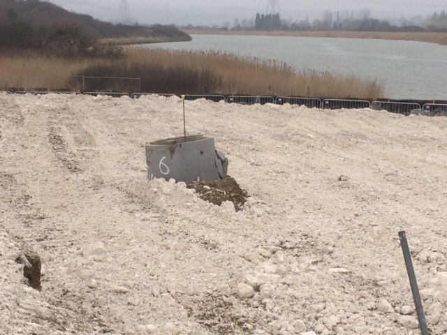
Another settlement rod who had a near miss with the same roller, good job it was protected.
5 – Who ordered the piles? – The first batch of cofferdam piles arrived this morning (AZ 20) but unfortunately the clutches had not been crimped. Before the batch was accepted the order was checked and it turns out it was our fault. The cost involved in sending them back to be altered was not the issue, in this instance it was time.
Solution – Level three precast concrete slabs left over from a design alteration on the crane jetty to create a welding bed. Tomorrow the center clutches will be welded together.

If only the piles had used crimpers instead of straighteners on their centre parting!
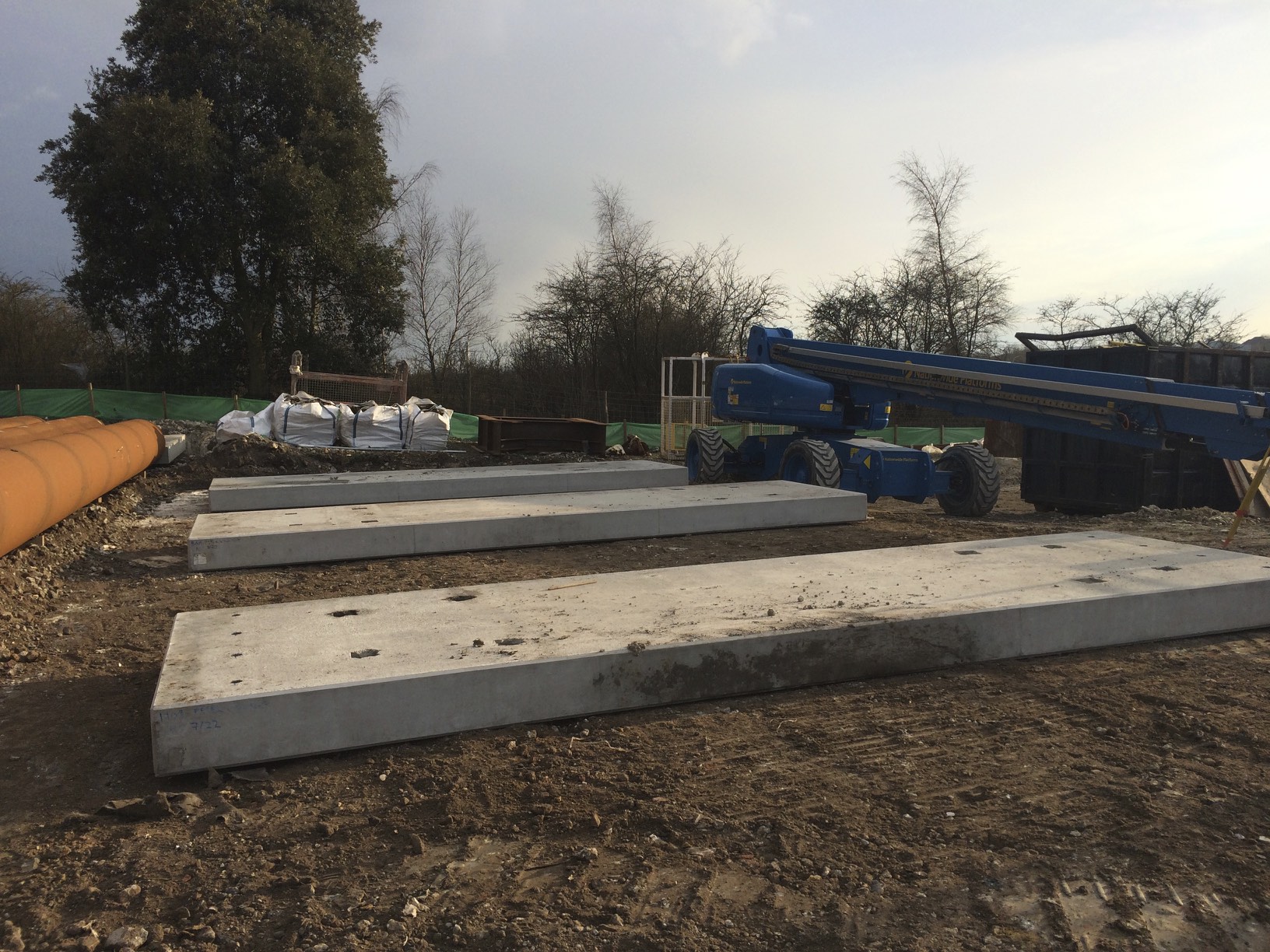
Our make shift welding yard
And finally – I saw our crane driver carrying what looked like a bottle of water, he must think I was born yesterday….my money is on gin or vodka!
Life on the Western Front
I’ve now been on the Peters Village project with BamNuttall for a couple of weeks and am slowly working out what is going on…we’re building a bridge!
The Peters Village project is a new community consisting of 1000 houses, schools, shops and so on. It is expected that in time it will grow to 5000 houses and as a result the local area infrastructure requires a large uplift. BamNuttall are responsible for the local area infrastructure but not the housing development.
The project office sits on the East side of the river, however the bridge section of the project is run from the West. Currently the site resembles a complex obstacle plan and is covered in a foot of mud making it look more like the Somme than a building site.
Project Overview
The project can be neatly split into a series of sections each with a dedicated team:
On Site Roads – These will feed the new built community and incorporate some ground preparation for the village.
Off Site Roads – 3km of road network to link the village to the surrounding area.
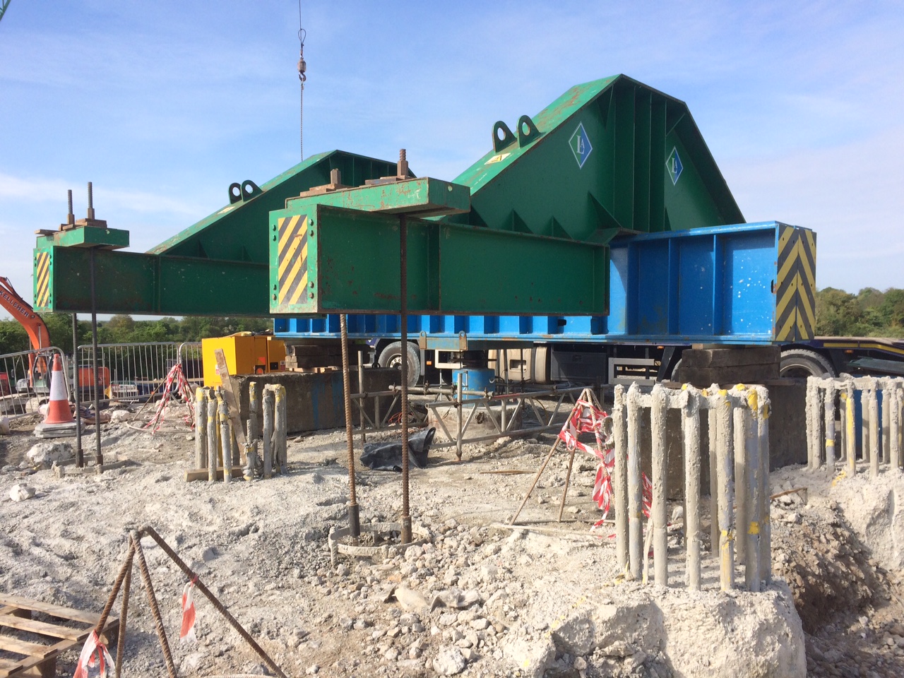
Medway Valley Crossing MVC – 150m pre-stressed, post-tensioned, cast in place river bridge
– 30m pre-stressed, pre-tensioned bridge over a live rail line
– 500m road and deep drainage linking the two
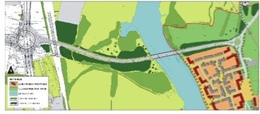
Kent council scheme proposal
Thankfully I am in the team responsible for the MVC, which will expose me to a much broader range of tasks and engineering issues. The river bridge sits on the critical path for the MVC section of work and that is the main focus of attention at this stage. The Rail Bridge has, and continues to, slip further behind regarding the start date, however, it has so much float in the schedule that there is no immediate concern.
Currently there are two key areas where efforts are being focussed, these are:
- The False Work Jetty
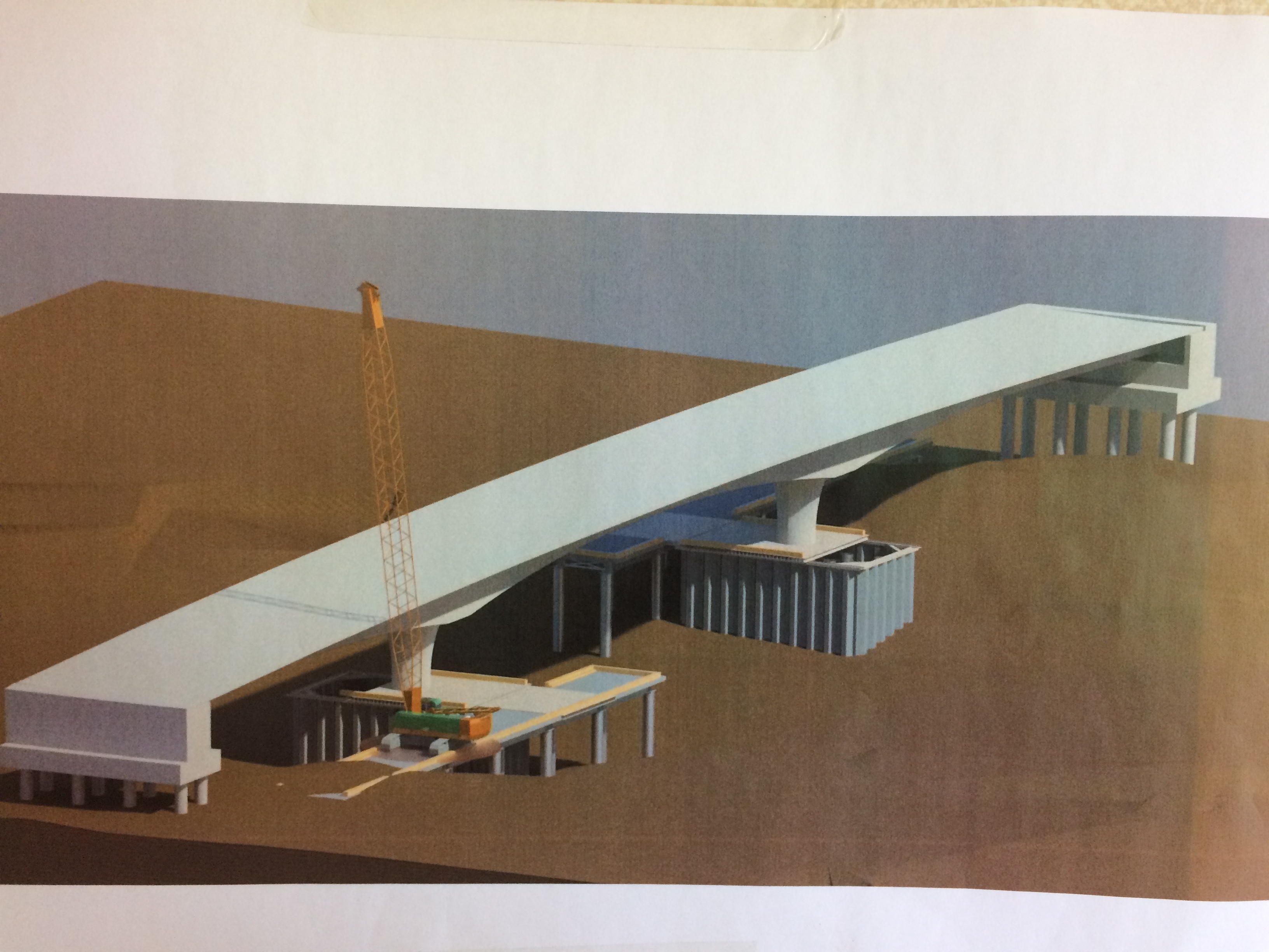
There is a requirement to maintain a 20m navigable channel open at all times. In order to achieve this a jetty will span out of each bank parallel to the main bridge; these will support the cranes required for construction. Directly below the main bridge a second jetty will be constructed to support the bridge false work. At present we have the west side crane jetty complete and are halfway through piling the west side false work jetty. Finally, two cofferdams will be constructed (the first started today) in order to provide access to construct the main bridge piers. Below are a couple of images that will hopefully add clarity to my poor explanation.
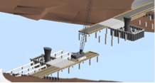
Crane jetty’s, false work Jetty’s, cofferdams and bridge piers
Late stages of construction, false work removed
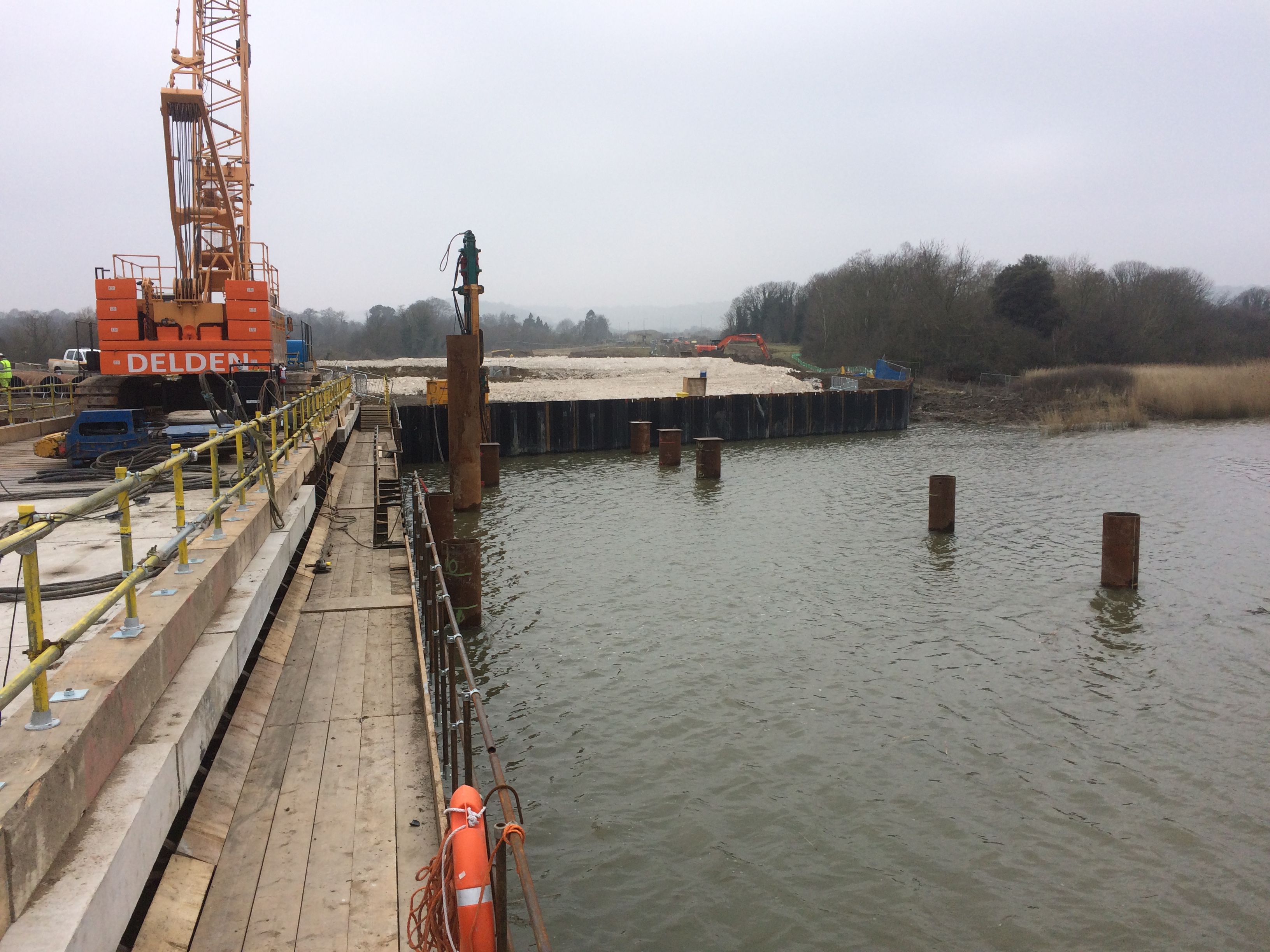
View from the end of the west crane jetty. The closest four piles
Mark the corners of the cofferdam. Taken at high tide.
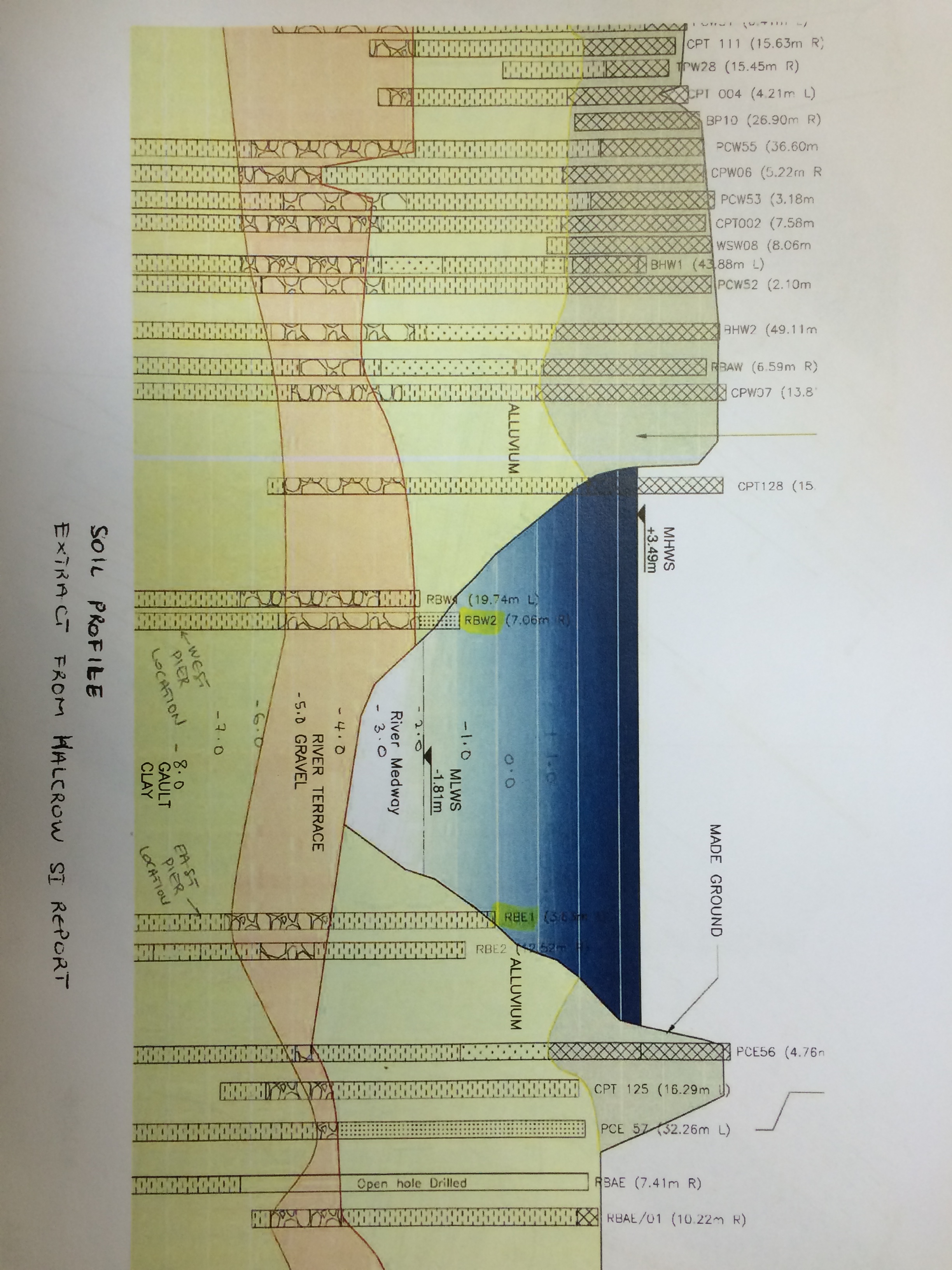
- Consolidation of Existing Ground
The ground profile across the site is clay over laying chalk with a thickening alluvial layer as you near the river. Currently the site slopes towards the river and is anywhere from 4-8m below the required formation level. Chalk is currently being imported from the cross rail tunnels to build up the level of the site and also to surcharge the clay and consolidate it. In order to increase the speed of consolidation band drains have been used. It is predicted that it will take at least six months to reach the required level of consolidation and a number of techniques are being used to monitor it. I will expand on this in detail in future blogs.
In Other News
Remember that moment on Ex Cofferdam when you messed up your calcs at 0200hrs on Wednesday morning and you can’t understand why no pump in existence is capable of emptying your hole…no…maybe that was just me, but fear not because we have a little blue pump on site that could not only deal with Ex Cofferdam but is actually callable of pumping out a rising tide on the Medway!!!!!!!!!
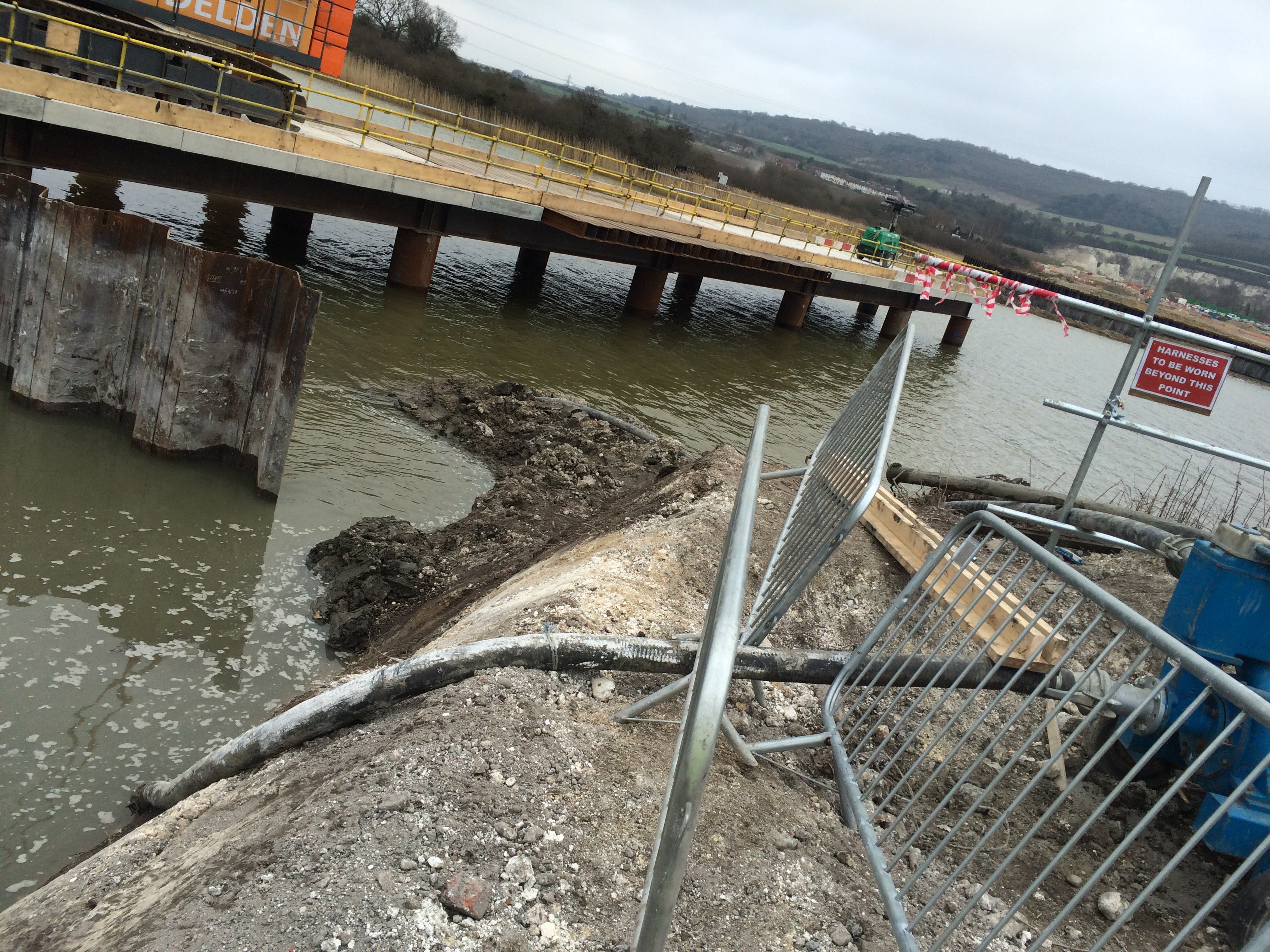
Thankfully a concrete plug now seals the end of the sheet pile wall and we’re not wasting diesel trying to fight nature any longer! I’m not sure if the poor lad monitoring the pump had been told to do it as a wind-up or not but as it was my third day on site I just smiled!
And Finally…
In case you were wondering, yes it is possible to eat an entire Soreen loaf, Mars Bar and drink close to a litre of Coke in the time it takes to drive an 18m pile into the ground. Should anyone wish to marvel at the evolutionary wonder that is our 110T crane driver please feel free to get in touch to arrange a private viewing.
