Archive
Transformer Blast Overpressure
The electrical team have a project to upgrade the electrical infrastructure within a communication network data center. Part of the scope of works is to create a new substation on level 10 of the building and install 2 new 1000kVA natural, air cooled transformers in separate fire rated compartments. The actual design and installation of the transformers will be the subject of a future works package.

I have been involved in the project both in the design of the ventilation system for the new substation and in checking the proposed design for compliance with Australian Standard (AS) 2067-2008 Substations and High Voltage Installations Exceeding 1 kV a.c.
The main cause for concern in the AS is that “where transformers are arranged in banks they should be separated by a fire barrier wall designed to withstand impact and blast forces in addition to its fire resistance”. The requirement to mitigate against blast is mentioned a further 2 times in the AS, but no detail as to how to mitigate for blast is provided. What we do know though is that if an explosion on one of these transformers knocked out the other, then the costs to the company in question would be in the millions of dollars per hour. One way or another we need to be certain that we have appropriately mitigated any risk.
Hoping for a quick fix, i trawled the internet for a blast over-pressure calculator. This wasn’t going to be that simple. I could find only one calculator that had been developed by Connell Wagner (Connell Wagner Arc Pressure Calculator), but the internet would only provide me with an image, so none of the calculations hidden behind. Furthermore, Connell Wagner were bought out some time ago and so I cant approach them for advice. I also found two UK Power Networks Engineering Design Standards which suggested the substation structure needed to be designed to withstand a blast over-pressure of 10kPa in a switch-room, and 5kPa in the transformer room.
In this case the transformers and their switch gear are co-located, suggesting a requirement for 10kPa. A quick check with the structures guys revealed that the existing slab on the 10th floor could at best support a dividing wall that can withstand 6kPa when the weight of the transformers was considered. We needed a more precise calculation.
I decided to set about producing my own calculator.
I found several useful documents that I used as the basis for my own calculation. Each of which appeared to base their work on a method developed by someone called Pigler back in 1976. Pigler was a much brighter man than I am but the general principles are as follows:
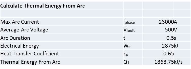
- The arc releases a certain amount of energy (Q), the proportion of which actually impacts the surrounding air depends upon a factor which accounts for the energy absorbed in melting the conductors and other losses.
- The arc energy causes an expansion of the room air (the first law of thermodynamics).
- That expansion increases the pressure on the structure.
Whilst this sounds simple, there are all sorts of factors to consider, such as the following:
- Is the transformer in a case or enclosure, and how does the expanded gas within that enclosure transition into the room?
- The transfer of energy to the air from the arc will not be uniform, and the subsequent rate of expansion will depend upon time and distance from the arc.
- The release of air from the transformer enclosure will either be through a vent or by a fracture in the enclosure.
- The impact of the arc energy on pressure is dependent upon where the arc occurs and what might obstruct air movement between the arc and the walls.
- Is there a vent provided within the room to release the pressure?
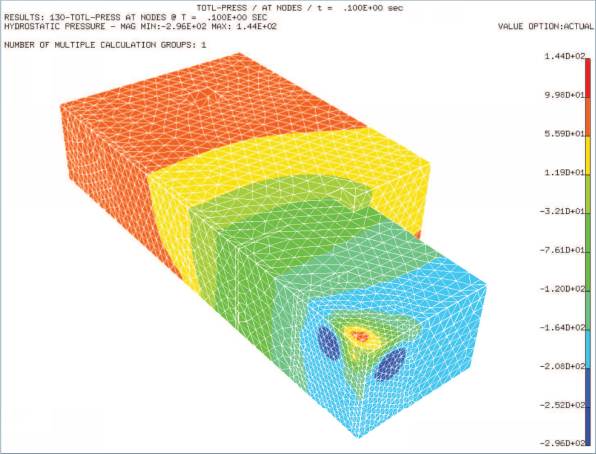
- A pressure distribution within the room will not be even, and there will likely be hot-spots as shown in the image below:

So, whilst Pigler’s method for determining over-pressure requires a PHD in maths and some computer programming skills, i recognized that I didn’t so much need an accurate answer, as an answer that proved that a 6kPa pressure was a worst case scenario. I went back to basics.
Where:
 and
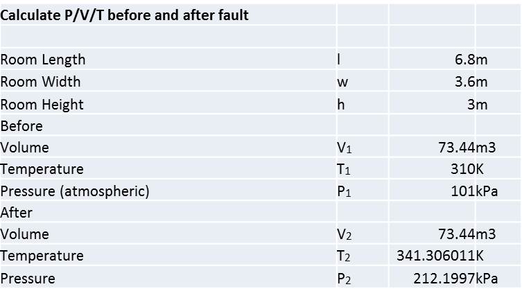
and Then, for a perfect gas:
Where:
Using
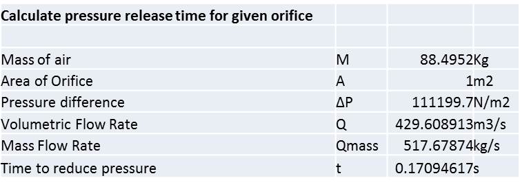
These results suggested an increase in pressure of 111 kPa which was a lot more than the 6 kPa I had to play with so I thought i would see what impact a pressure vent would have in the room.
Where:
![]()
![]()

![]()
This suggested that the increase in pressure could be dissipated by a 1m2 vent in 0.17 seconds.
Essentially though, the process above only served to prove that this sort of calculation needed to be done properly, rather than assuming the arc energy influences all the air in the room at once, which it wont.
I called Siemens and persuaded them that they were in the running to supply the transformers. They modeled the parameters I gave them in some computer software and provided the following:

The result here was a pressure peak of 1.58 kPa with a 0.2 m2 vent (provided for by the ventilation duct in this case) which is comfortably acceptable in the substation.
What did I learn?
The chances of an arc fault on a dry transformer are very small, so small that this modelling would not be done for a dry transformer.
The chances of an arc fault on switch gear are also very small (approx 1 in 10,000) but the possibility is enough to model blast over-pressure.
The risk of explosion only really exists where the transformer is enclosed in a case. A sealed case, such as that on an oil cooled transformer allows the build up of pressure in a relatively small space, which can lead to an explosion. In a dry transformer open to the air in the room, the air will heat gradually and there is a much larger mass to absorb the heat. A small vent is sufficient to allow the dissipation of expanded air.
An explosion in an oil cooled transformer carries a high risk of fire. A dry transformer has nothing to burn.
Only use dry transformers inside buildings.
Pigler was a mathematical ninja, even surpassing the intellect of Brendan (I recon). Whilst I am sure even I could significantly improve upon the basic spreadsheet I produced, the array of factors involved in calculating blast over-pressure from an arc fault lead me to recommend that anyone who comes across this in the future just calls Siemens and you’ll get something back in a couple of hours.
Chilled Water System Heat Exchanger
2015 has got off to a fairly slow start for the Building Services team at Jacobs in Brisbane. There is a lot of work in the pipe line that we are expecting to land at any moment, but for the time being I am keeping busy with some relatively small research tasks, blogging and the mountain of reports that need to be submitted in January!
This task is to source a heat exchanger to interface between two separate chilled water loops, each serving a different hospital.
Construction of the Gold Coast University Hospital (GCUH) for which Jacobs won the contract for the building services design, was completed in 2014. The client, Queensland Health, entered into a contract with a private health service provider to supply various utilities / services to the new Gold Coast Private Hospital (GCPH) which is to be built on an adjacent site. The services / utilities include standby power, fire mains water supply, HV system reticulation, potable and reclaimed water supply and chilled water for the air conditioning system.
The design and documentation for the GCUH chilled water system was written based on an assumption that the GCPH chilled water ring main would be directly connected. However consideration is now being given to the possibility of maintaining segregation between the two systems by having two separate ring mains and a heat exchanger as the interface between the two.
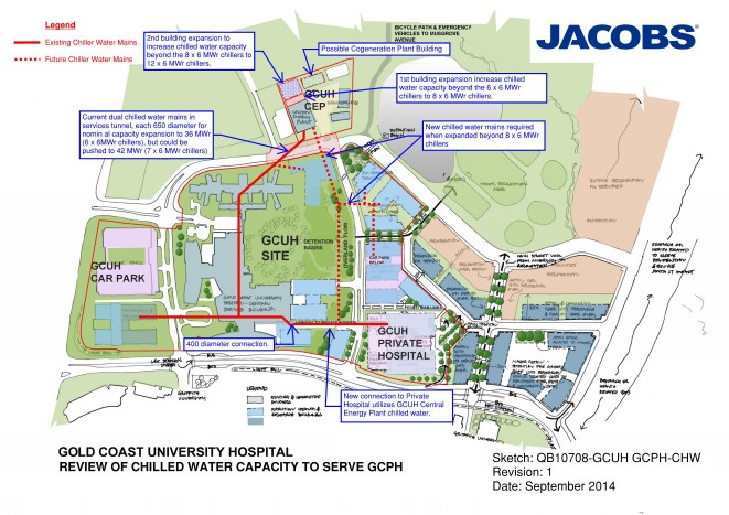
The maximum working load of the existing GCUH is 22.8MWr (based upon assessment of current use and estimated increases when the hospital is at full working capacity) and the maximum working load of the GCPH is assessed to be 3.8MWr. With a required redundancy capacity of n+1 (one spare chiller to allow maintenance as required) and a combined maximum load of 26.6MWr, the requirement is for 6 x 6MWr chillers. This is an increase of 1 from the existing chiller set and these additional works have already been allowed for within the existing plant room.
With the maximum capacities in mind, the specified parameters within which I have been told the heat exchanger must work are as follows:
- 3.8MWr max cooling
- Split of 6^C, entering the heat exchanger on the GCUH side at 6^C and leaving at 12^C
- Approach of either 1/2^C or 1^C, the temperature difference between the outlet temp of the GCPH side vs the inlet temperature of the GCUH side.
So before I contacted suppliers, i calculated the volume flow rate of the loops as follows:
Q = M C ^T
3.8MW = M x 4186j/Kg x 6^C
M = 151 l/s
Other considerations are the pressure drop across the heat exchanger, which will dictate the pumps required, and the pressure of water the heat exchanger must be able to cope with. I have been advised that the pressure drop would be in the region of 50KPa at best and should probably not go much beyond 100KPa. I have assumed the pressure to be in the region of 10Bar as I have no further information at present.
I contacted two suppliers, Alfa Laval and Swep, who provided options as follows:
| Ser | Description | Capacity | Approach | Split | Volume Flow Rate | Pressure Drop | Unit Cost | Quantity | Total Cost |
| MW | °C | °C | l/s | kPa | AUD | AUD | |||
| 1 | SWEP B649 | 4 | 1 | 6 | 160 | 100 | 13265 | 4 | 53060 |
| 2 | SWEP B649 | 4 | 1 | 6 | 160 | 50 | 14720 | 4 | 58880 |
| 3 | SWEP B649 | 4 | 0.5 | 6 | 160 | 13720 | 16 | 219520 | |
| 4 | Alfa Laval HEX | 4 | 1 | 6 | 160 | 100 | 108919 | 1 | 108919 |
| 5 | Alfa Laval HEX | 4 | 1 | 6 | 160 | 100 | 130698 | 1 | 130698 |
| 6 | Alfa Laval HEX | 4 | 0.5 | 6 | 160 | 224427 | 1 | 224427 |
Conclusion
Whilst the use of a heat exchanger simplifies maintenance ownership issues between the two hospitals, and the separate chilled water loops provide an element of isolation should there be any problems on the GCPH loop, that comes at significant cost.
The system would require additional pumps, again with an n+1 redundancy, to pump the water through the GCUH side of the heat exchanger, whereas if the chilled water is connected directly there is only one pump set required to service the branch.

The capital cost of the heat exchanger itself can be seen in the table above and is significant, added to that is the requirement for additional pumps to serve the GCPH side of the exchanger as shown in the diagram below. These pumps also have significant capital cost and there are also the associated maintenance costs to consider. There is also the added issue of having to house the heat exchanger and pumps somewhere within the GCPH.
Based upon these factors, I cannot see how the use of a heat exchanger could be considered a viable option, but at this stage I have just been tasked to source options. I will discuss with the PM as to the way forward.
Lunatic Asylum
On my second day in the Jacobs design office, a call came in from a Brisbane mental asylum for help with an existing air conditioning system. The system was installed as part of a refurbishment of a single story heritage building within the asylum grounds in 2008, and has not worked properly since. The installer has made several return visits to ‘fix’ the system but has failed to do so. As the warranty has now expired, the maintenance team decided to employ a consultant to fix the problem once and for all. I put my hand up to run with the task.
The Task
Design an air conditioning system for the building which uses the existing split units to best effect. The solution must also be feasible to install whilst complying with the restrictions placed on heritage buildings.
Background
The buildings principal use is for offices, and the nature of staff complaints suggest issues with the capacity of the system and with air distribution. Someone, somewhere is either too hot or too cold, and any attempts to fix the problem have just shifted it to another room. I went to recce the job and found that they currently have 3 outdoor condensing units, each with a cooling capacity of 15.2 Kw, on 3 refrigerant ring-mains, feeding a series of indoor head units of varying capacity. It was immediately obvious that the indoor head units were poorly distributed among the rooms, and that there was no outdoor air supply other than natural infiltration. I collected details of the outdoor and indoor units, the room occupancy, noted the electrical equipment in each room and got a feel for the composition of the roof and walls. The site manager provided me with drawings of the building which had room sizes etc.
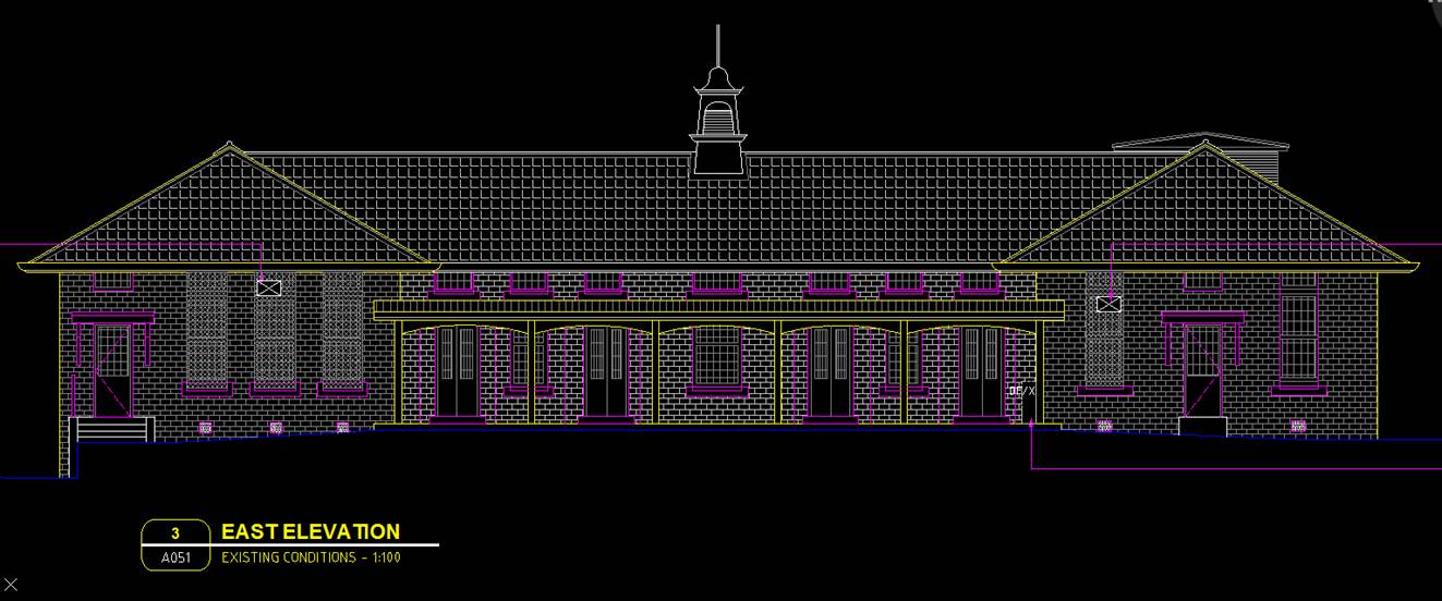
Figure 1 – East Elevation
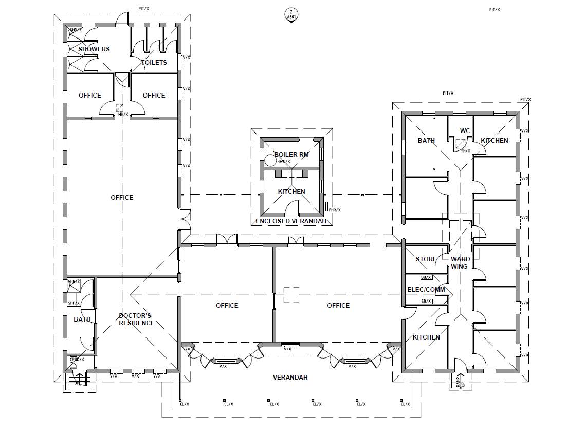
Figure 2 – Floor Plan
Due to the building being heritage listed, the site manager advised that the re-design should to use existing penetrations through the ceiling and walls. This will mean that refrigerant pipes will be visible on the inside of the rooms, and any ventilation will need to use either existing ceiling access panels (of which there are very few) or windows.
Heat Load Calculations
The heat load software used by Jacobs Australian offices is Camel, and is significantly less capable than Hevacomp as it only calculates heat loads. It took me the best part of a day to input the building data using the Camel manual as a guide. The project was an ideal size to learn the software and to figure out the little tricks that help speed up the data entry.
The key outputs from Camel were as follows:
- Individual room heat loads..
- Condenser cooling capacity required per zone.
- The W/m2 per zone, which gives an indication as to the accuracy of the output data – usually in the region of 200W/m2 for an office.
- Coil dew point
- Sensible heat factor.
The rooms are currently grouped into 3 zones, each serviced by a single 15.2Kw outdoor condensing unit as shown in Figure 3 below.

Figure 3 – AC zones and existing Fujitsu head unit layout.
The Camel heat load results clearly showed there was a problem with capacity in Zones 2 & 3, which tied in nicely with the information from the user.
- Zone 1 required a cooling capacity of 17Kw at its peak load.
- Zone 2 required a cooling capacity of 26Kw at its peak load.
- Zone 3 required a cooling capacity of 38.6Kw at its peak load.
So, the problem was three fold; insufficient cooling capacity for Zones 2 & 3, poor distribution of head units within the rooms and no outside air ventilation.
The Solution
Insufficient cooling capacity – Further divide the rooms into additional zones so additional condensers can be added to provide the required cooling capacity. Condensers to be selected form Fujitsu range based upon size requirements.
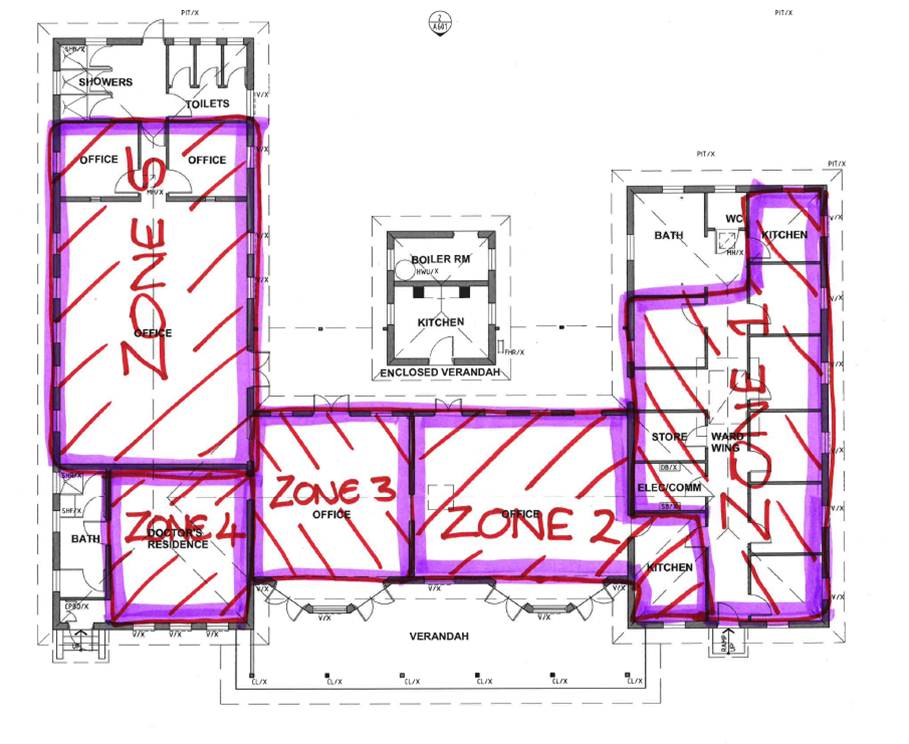
Figure 4 – Revised AC zones.
The revised zones require the following cooling capacity at their peak:
- Zone 1 – 17.0Kw – can utilize existing condenser unit.
- Zone 2 – 13.3Kw – can utilize existing condenser unit.
- Zone 3 – 4.48Kw – requires additional condenser unit.
- Zone 4 – 17.4Kw – can utilize existing condenser unit.
- Zone 5 – 20.3Kw – requires additional condenser unit.
Poor distribution of head units – Re-distribute head units and add units to rooms where current capacity is insufficient. The solution below utilities all but one of the existing head units but has an additional seven units of two different sizes. Figure 4 below shows the re-distributed head units. The purple represents a head unit and the number correlates to a particular unit capacity.
- 7 – 2.15Kw
- 9 – 2.8Kw
- 14 – 3.8Kw
- 18 – 5.4Kw
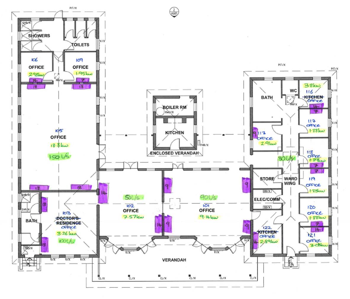
Figure 5 – re-distributed head unit layout.
Ventilation – Provide pre-conditioned air to each of the spaces so as to improve the efficiency of the system and reduce the load on the indoor head units. This is proving to be the most complicated part of the problem in terms of how to provide conditioned ventilation to each space, without any works that could cause problems with the buildings heritage status. The options being considered at this stage are; providing heat recovery ventilators to each room through windows, installing a centralised pre-conditioner in the roof space below the clock tower and ducting to the 5 key spaces (for zone 1 I am thinking to put air into the corridor rather than individual rooms), or a chiller unit with a chilled water loop.
At this stage, my thoughts are as follows; the heat recovery ventilation to each room would be the easiest option but the units are 1m x 1m x 2m and weigh 76kg so mounting them in a window (I cannot put any new holes in the walls due to heritage restrictions) would be difficult; the centralised pre-conditioner would potentially provide the best efficiency but it will depend upon the ceiling space available and flow/return air possibilities through the clock tower; the chiller unit seems overkill for such a small building and would require chilled water to be piped around the building.
I have spoken to a supplier to get and understanding of the options, and have another recce planned for tomorrow to see which options are physically possible….
Services Engineering with John Holland – Part 2
So, having had mixed feedback on Part 1, I will forge ahead with Part 2….
The Project
Comprised of 3 Lots; Lot 1 – additional works to the plant room in a neighbouring building to provide chilled water AC to the new buildings; Lot 2 – a 6 storey high-tech arts and dance building with acoustic sound studios; Lot 3 – the renovation of existing heritage military barracks into a student arts centre. An AUS$60 million project with intricate architectural detail, a lot of off-form white concrete, acoustically isolated studios and state of the art AV systems.
From what I have heard of other projects, there are advantages and disadvantages to being on a relatively small project. In the time I have been here, I have been able to develop a sound understanding of the services for all 3 Lots, and have been immersed in the structural, facade and finishes aspects of the project as well. The amount of off-form concrete means that there are vast numbers of cast in conduits that are later used to carry power and communications cables, and the accurate location of cast in penetrations for services is vitally important given the exposed concrete.
Perhaps the negatives are that there is not the extent of different services in this project compared to those you would find in a larger project (e.g. a hospital). For example I have had nothing to do with HV power; something I know Ollie has been heavily involved in at the Perth Childrens Hospital.
Being in a small team (c. 16 people) in one site shed means that I have really got a good feel for the politics behind decisions made and the contractual ‘game’ that is played out between subcontractors, head contractor, client and consultant.
The Project Team
The basic team org chart is shown below. The team has changed considerably over the last 8 months with all bar 3 of the project team members changing over. The only team members who have survived from the start are the PM and my services colleague. Some of the turnover im sure can be explained by the uncertainty over the future of John Holland (JH). They are up for sale and the buyer is as yet unknown. Nobody knows for sure if the buyer will keep the building side of the business. There is also a lack of work in Queensland; with a couple of other projects finishing up in the coming weeks, we are soon to be the last JH building project in Queensland. There are more projects in the pipeline though, i’m told.

The military equivalent of the foremen would probably be somewhere between a Cpl and a SSgt depending upon experience. They drive the subcontractors on site, but rely upon the engineers to ensure the necessary design information is available and to resolve issues as they arise, such as services clashes. I was surprised to find that there are actually no ‘proper’ engineers (either chartered or with an engineering degree) on my site. We are referred to as ‘Pretengineers’ by the foremen. My PM has got to where he is from being a chippy and the Safety Manager is an ex Australian Army RSM.
The dynamic has not been at all what I expected. On my site the foremen run the show and the engineers do the administration as required. This, in my opinion, makes the team very reactive rather than proactive, particularly as the Senior Project Engineer resigned making it harder to gather the engineering team to do any forward planning.
Roles & Responsibilities
Despite the lack of knowledge of drawings and general terminology, responsibility came quickly. My primary responsibilities are below with a rough percentage of my day allocated to the task.
- Services Co-ordination Meeting – With the services trades still very much clearing up design issues and generating shop drawings in the early weeks, I took responsibility for running the weekly services coordination meetings. At this stage the meeting was attended by each of the services Project Managers; Electrical, Mechanical, Hydraulic, Fire and AV Systems. The principal aim was to provide a forum to discuss clashes and design issues identified during the shop drawing process. In the last 2 months, the meeting has become more of a site coordination meeting between services and finishes trades with attendance primarily at the site supervisor level. (5%)
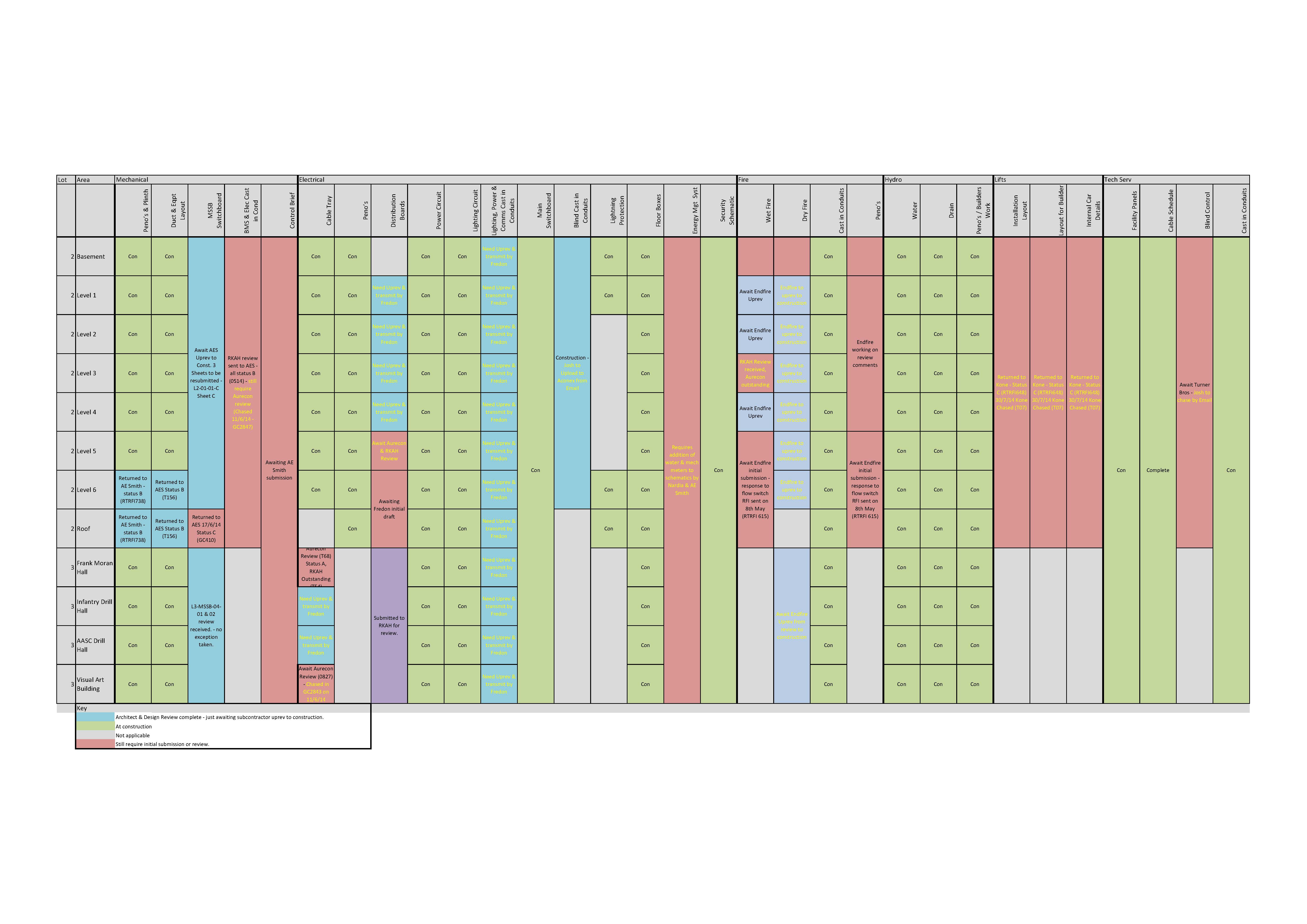
- Managing Services Shop Drawing Reviews – The specification documents call for certain shop drawings to be submitted to both the Architect and Consultant for review. These need to be chased, and tracked, a deceptively complex task given this involves in the region of 400 drawings from 5 trades, each of which may need to be revised and resubmitted anything up to 6 times. I developed the spread sheet below to capture the status and relevant Aconex correspondence numbers. When I arrived on the project we were probably about a third of the way through the process. (20%)
- Services Correspondence – Responding to requests for information from the subcontractors. I have nothing to reference against, but I’m told that this job had an unusual amount of incomplete design. Throughout the shop drawing process and during install, these gaps in the design such as areas on ‘hold’ and missing set-out for services have generated a significant number of RFI’s, each of which need checking (to ensure we definitely don’t have the information) before they are sent on to the Client / Architect (as the lead consultant). I have no idea how this compares to other sites and would be interested to know, but I have sent over 200 RFI’s to the client / lead consultant (the other services engineer around 480), and nearly 1000 other related correspondence. The project uses Aconex to track correspondence which is pretty good once you work out how to use it. I did spend the first couple of months tracking correspondence through a spread sheet though, before I got the hang of the software. (40%)
- Quality – Managing the services trades ITP’s. This involves checking cast in conduits and penetrations in slabs before they are poured and getting trades signatures on the ITP. The same checks must be carried out before walls and ceilings are closed up. Each trade should then provide a copy of their own ITP as an annex to ours. As you can imagine, this is not top of their priority list. There is also a requirement to understand what the specification documents call for so as to check the trades are not taking short cuts to save a buck. (10%)
- Checking Variation Prices – Ensuring subcontractor claims for variation costs are legitimate and checking the prices against the schedule of rates. This can be time consuming as subcontractors will regularly chance their arm at recovering costs that do not constitute a variation and are quick to jump on the fact that due to our high staff turnover, we struggle to retain information on previous conversations etc. As such time is spent trawling through correspondence, meeting minutes and drawing revisions to determine where cost should lie. (5%)
- Safety – Various site safety requirements such as routine hazard inspections, reviewing subcontractors safe work method statements, issuing concrete penetration, excavation, isolation and hot works permits and periodic reviews of the Activity Method Statements (AMS). (5%)
- Clash Resolution – On site resolution of small clashes that are not design related. Usually takes some diplomacy as each trade thinks the others should move their services around them. (10%)
- Occasional Tasking – Researching and delivering solutions to problems such as ensuring sufficient fire hydrants are installed to maintain fire code compliance during construction and developing a solution to providing temporary ventilation through the building once the façade is installed. (5%)
The Routine
- Site opens at 0630hrs – arrive at work.
- Get a brew and quickly check last nights emails.
- An early site walk, which will inevitably generate safety or clash issues to be resolved.
- Deal with correspondence and chase outstanding RFI’s
- Another site walk.
- Team meeting.
This should lead on to Part 3 where I will try and summarise key lessons….
Services Engineering with John Holland in Brisbane – Part 1
As the only non-engineer on the PET E&M 55 course, I knew absolutely nothing about what to expect during phase 2 & 3 of the course. Furthermore, selecting where to go seemed like a lottery. What follows is a brain dump of how i ended up in Brisbane, and what i have done since i got here. Hopefully it will be of some assistance in selecting placements and helping the non-engineers understand what is in store.
Placement Selection
I have no marriage / family commitments, so arrived on the course with the aim of getting to Oz. That said, i was also pretty concerned about how i would cope with the academia on the course; my BSc in Disaster Engineering & Management may as well have been a degree in brewing, given the ratio of socials to lectures. Furthermore, do not be mislead by the word ‘engineering’ in the degree title, as the complexity of the engineering covered was little more than building tripods and digging pit latrines.
Early exam failures started to make me think that i should stay in the UK where i could have better access to academic support (PEW). There was also an element of scaremongering about John Holland (JH) getting their pound of flesh due to the associated additional costs, which would reduce available study time and increased pressure around assignment submissions.
In the end I was fortunate to have a moment of clarity. The placements are, in my opinion by-and-large luck of the draw, even for those who arrange their own in the UK. My management could be good or terrible wherever I ended up, any project was guaranteed to be interesting as it would all be new. So my decision to plug for Oz boiled down to this; I had never been here but only heard good things, Ozzies were rumoured to enjoy a few beers and a similar understanding of banter as the Brits, and above all, hot girls in lycra.
My advice – go with your instinct.
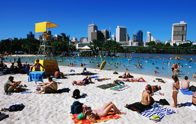
South Bank, Brisbane

Casual (girls) lycra
Australia
Awesome!
Pre-Arrival Admin
Getting early information whilst in the UK was like getting blood out of a stone and in the end I contacted my PM to be through Linked In. When I got here all my PM seemed to have been told was that some services ‘guru’ from the British Army was coming and that he needs to be accommodated and given a car. The lack of information had clearly caused rumour amongst the small team, and I later found out that the services engineer whom would become my mentor thought I was being brought in to replace him, which explained the initial uneasy dynamic.
I managed to negotiate $650AUS per week for my accommodation, which in hindsight, was pretty good for Brisbane which is definitely cheaper than Perth or Sydney. I live in a spacious 2 bed apartment in a decent suburb. I can cycle to the CBD or to work in 15-20 mins and am almost on the Brisbane river (Google: Dixon St, Newfarm). Whilst there was a lot of property available, the need for furnishings narrowed the field considerably. Of the 2 weeks relocation leave, i spent just over one finding a place to live and got to know the city for the second.
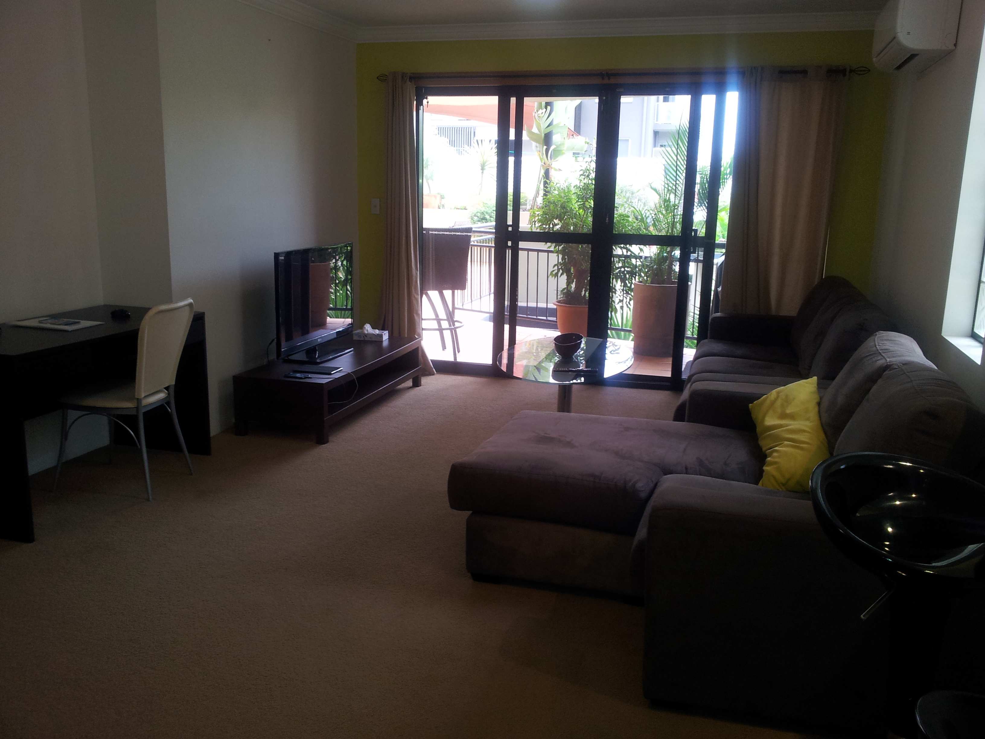
The pad
I am still a little unsure as to why so little information about who I was and why I was there was passed to my PM. John Reddie (the JH LO to PEW) is a calculated man so I have no doubt it is a deliberate move but I have been unable to work out why. Whilst we get the Coursework Instruction from PEW, a single document from PEW outlining key information to a PM, such as course objectives, coursework requirements, accommodation allowance / entitlement, request for support in terms of study time etc. would save some early, slightly uncomfortable, negotiations. In the end I wrote one myself and talked it through with the Senior Project Engineer as something to fall back on later. The trigger for this was repeated attempts to get me to take over some of the structural engineers workload such as testing concrete etc.
Starting Out
Very slow for the first couple of weeks. I had no desk, no computer, no phone and no safety boots. For the first week my job was to perch at the plan bench and familiarise myself with the project drawings. This revealed my first and probably most significant weakness; i knew nothing about architectural/design drawings. A basic understanding of what drawings i could expect to find and how to read them would have been a huge help. Furthermore i knew nothing of the other key project documentation i should be looking for such as specification documents, the project management plan and the safety management plan.
First impressions count as we know, so the early days of asking billy basic questions lead to me being perceived as a work experience kid by many I’m sure. This made it harder for me to get traction for the things that I could add value to, and set the starting bar for earning respect amongst the team unnecessarily low. In hind sight, I could have dramatically reduced the quantity of basic questions if I had had access to and had trawled through the intranet. Unbeknown to most of my project team, details of procedures, the most up to date forms, and checklist prompts to assist in safety walks etc. could all be found on the intranet.
My advice – ensure you are familiar with reading drawings before you arrive on site and read the following key documents (or equivalents) as a matter of priority; Project Management Plan, Safety Management Plan, Head Contract, Sub-Contracts and relevant trade Specification documents. I also recommend having a good trawl through the company intranet (IMS in JH) as there may be a raft of useful information to save you reinventing the wheel.
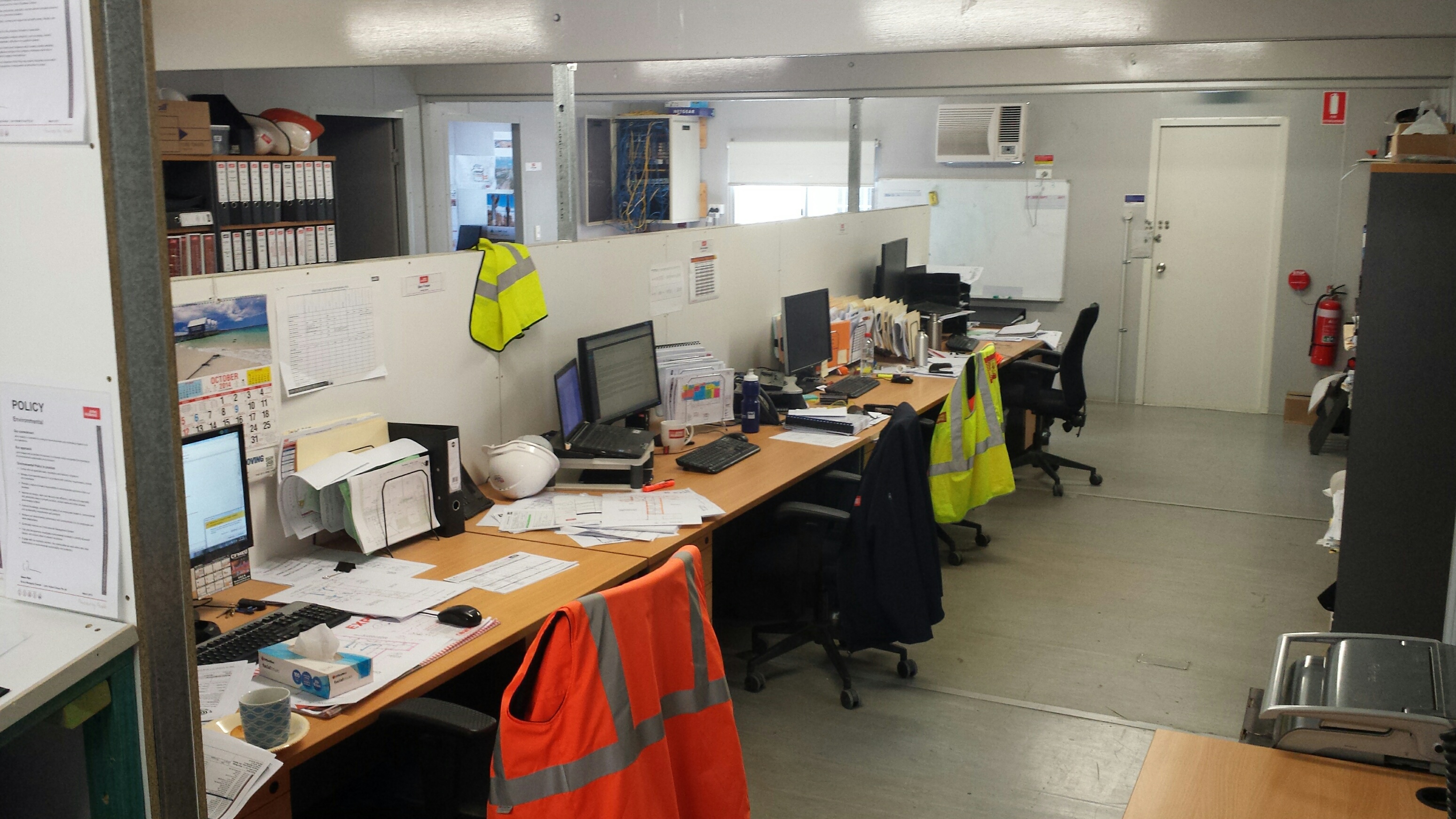
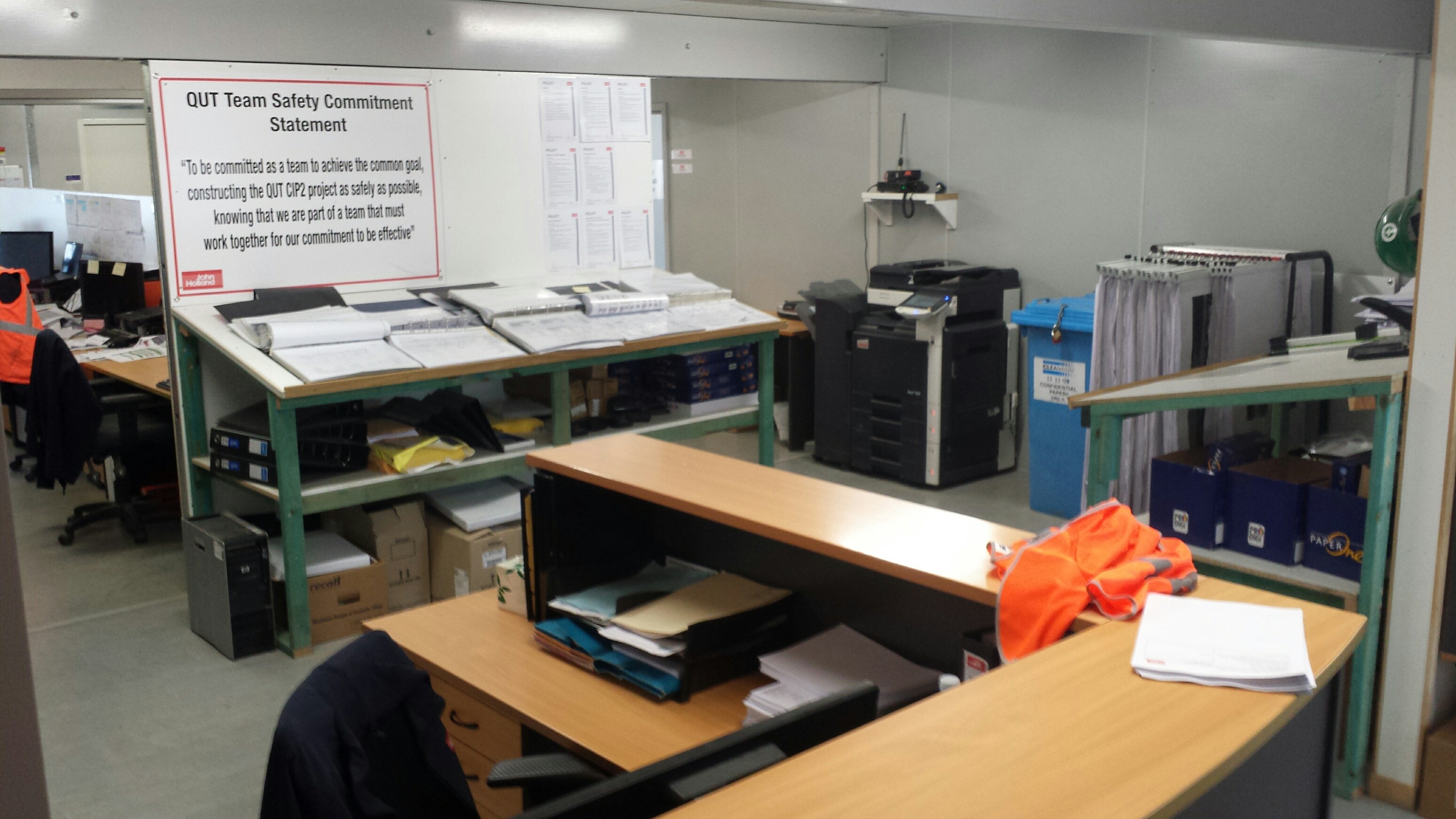
The JH site shed.
Look Forward To….
In Part 2 of Services Engineering with John Holland in Brisbane I will try and cover the following:
- The Project
- The Project Team
- Roles & Responsibilities
This should lead on to Part 3 where I will try and summarise key lessons.
Let me know if there is anything else that could be of use……
Fighting Fire with Fire
The last couple of weeks have been dogged with industrial action, which has resulted in the loss of around 4 days work. The dispute is centred around a change to Australian legislation governing the access of union officials to site. Previously, a union official could access any site if they deemed that there was an urgent safety issue, and demand that work cease until the issue had been resolved. This translated to a carte blanche for union officials to wreak havoc on construction programmes, and chuckle while site management frantically tried to replace a first aid box that had a broken seal, for example.
The new laws require union officials to give 24hrs notice to site management, so as to enable them to rectify the issue without having to stop work on the site. This has gone down badly with the unions who are doing their best to beat major companies (as far as I know, this is not restricted to John Holland) into flouting the law and allowing immediate access. The tactics to date have been to call 2 hour union meetings, which they are entitled to do. The clever part is that they will hold meetings for select trades at different times of day so as to ensure there are never enough of the right people on site to pour concrete.
There have been several incidents of union officials turning up on site and gaining access before John Holland staff have a chance to respond. The JH head office response has been to employ an Ex Columbian Army Commando to guard the site – hence the blog title, fighting fire with fire. Whilst he really does look the part as a visual deterrent, it would be severely frowned upon if he were to employ his ninja skills to scalp a union rep at the entrance to site. As such has been instructed to call the PM if he sees anything. His presence has also antagonised the union members; an outcome I think most of us could have foreseen.
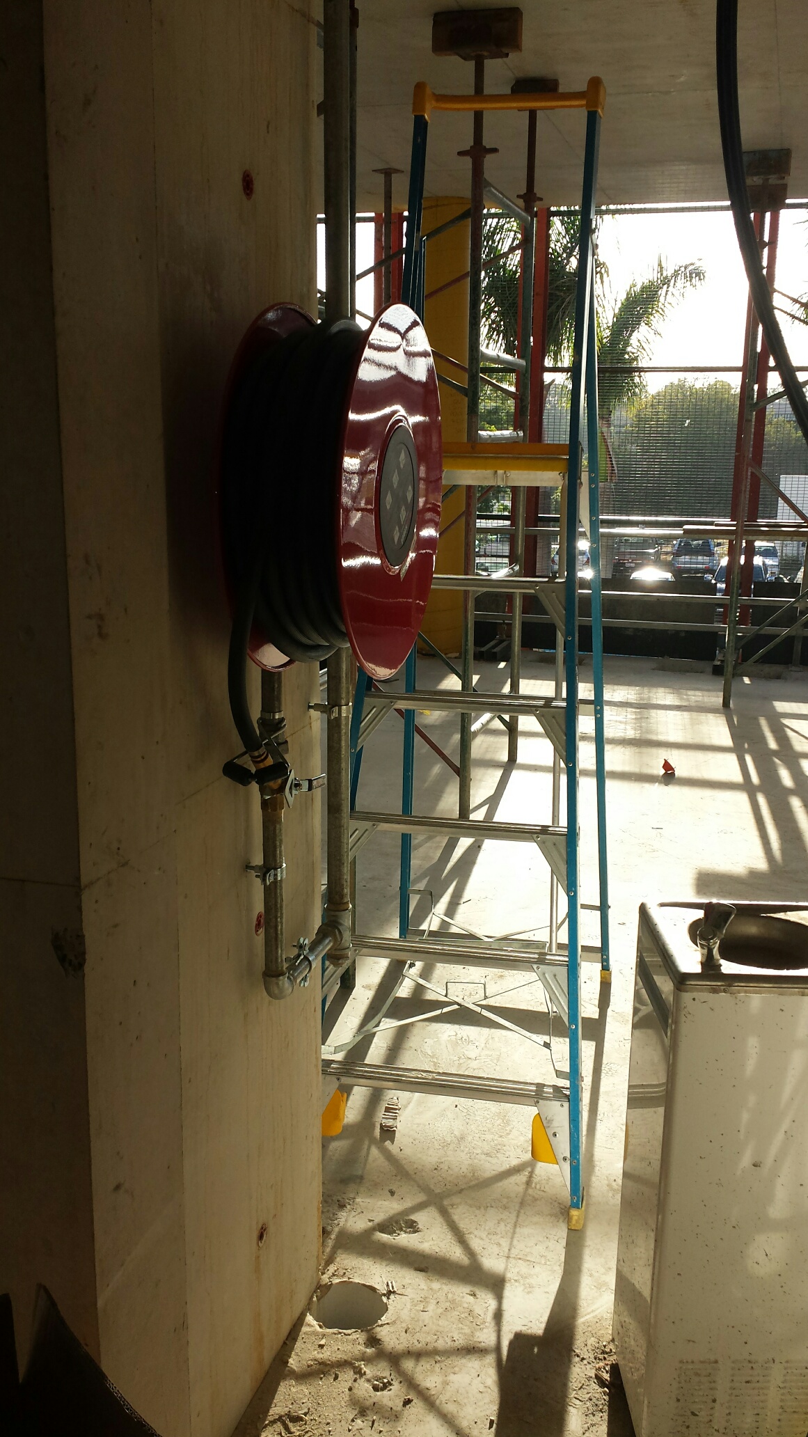
Switching subjects, I was hoping for some advice from the floor. As we are about to pour one of the level 5 slabs, the Building Code of Australia suggests that we are obliged to have a fire hydrant system and fire hose reels in place and working up to level 3. Several JH staff members are concerned with the security of the fire hose reels, particularly as we are in the middle of a Uni campus and the little scrotes have accessed site after hours on several occasions. I only need to think back to the time Steve Crosby-Jones emptied out a 30 storey tower block of students after a couple of beers at Cov Uni, to gauge the likelihood of turning up to a flooded site in the morning. This site isn’t particularly hard to access so the security of the hose reels will need to be localised. It will also need to allow easy access to use the hose if required. Does anyone have any experience / suggestions that they could share?
I have included a picture of one such fire hose reel to help you visualise the problem.
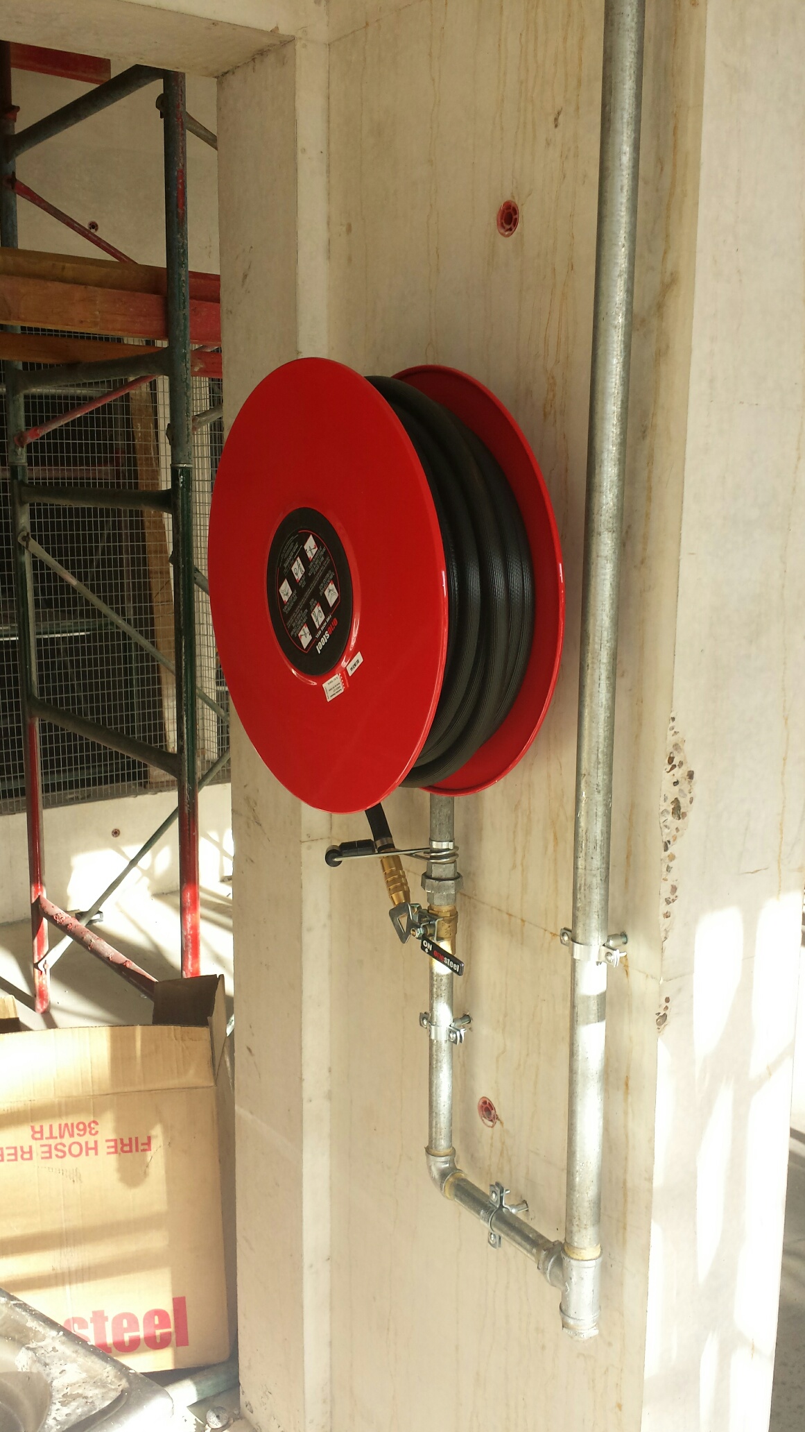
Fire Hose Reel on Level 2
From the other side
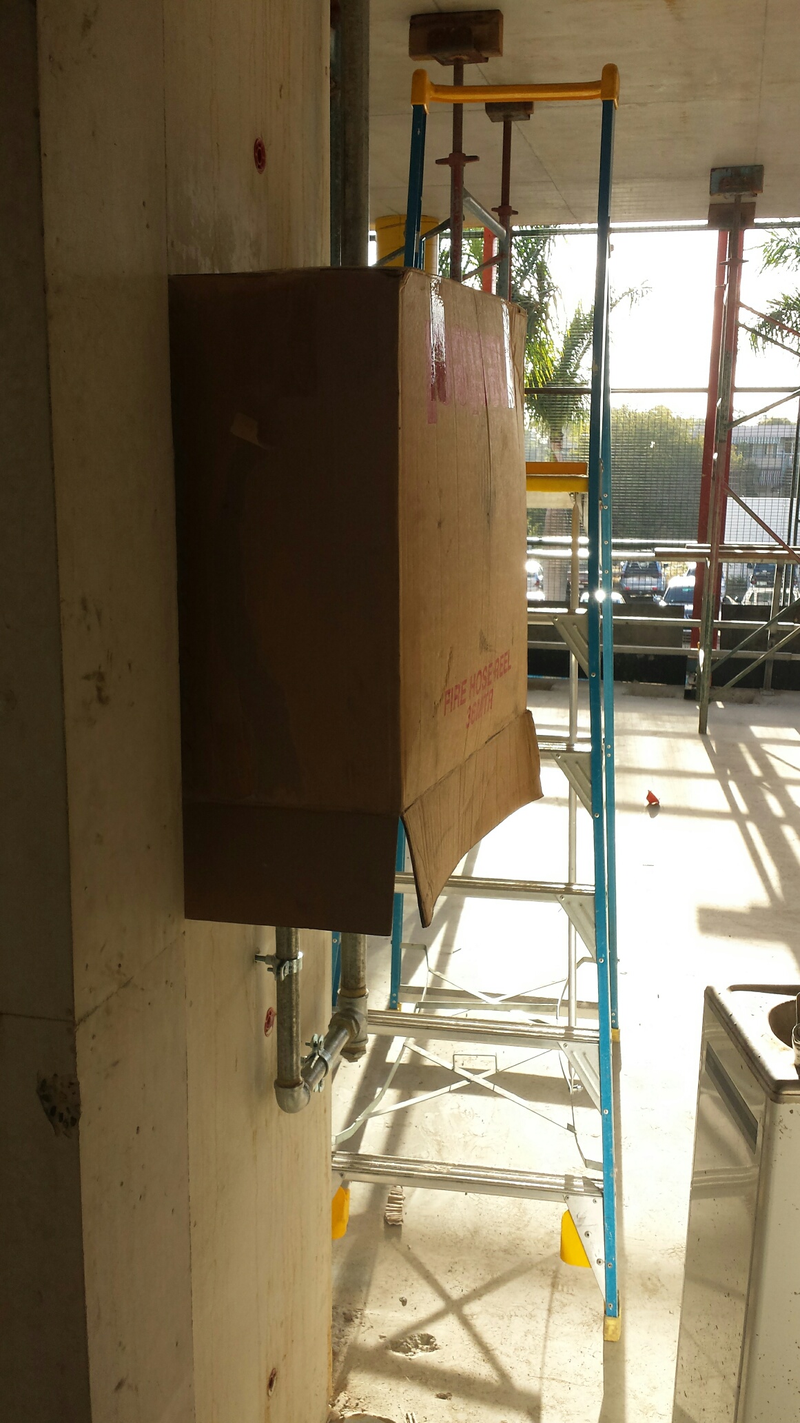
Demonstrating the current protection.
In other news, we had a work trip to see the Brisbane Broncos play the Gold Coast Titans on Friday. Those who know me will appreciate that a fair few beers were consumed, particularly as it turns out that my boss is even more of an animal than I am! The result was me doing the plank on a kerb stone whilst trying to get rid of hiccups at 3 in the morning.

The plank!
QUT CIP 2 – Blog 1
Well despite only having been on site for a couple of weeks, I feel like i have enough to warrant my first blog.
Project. A $60m contract to build a creative industries precinct for the Queensland University of Technology (QUT). The project is to construct a multi-purpose education facility comprising of teaching spaces, office accommodation and specialist teaching studios for the creative arts faculty (music, dance, drama and visual arts).

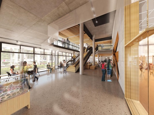
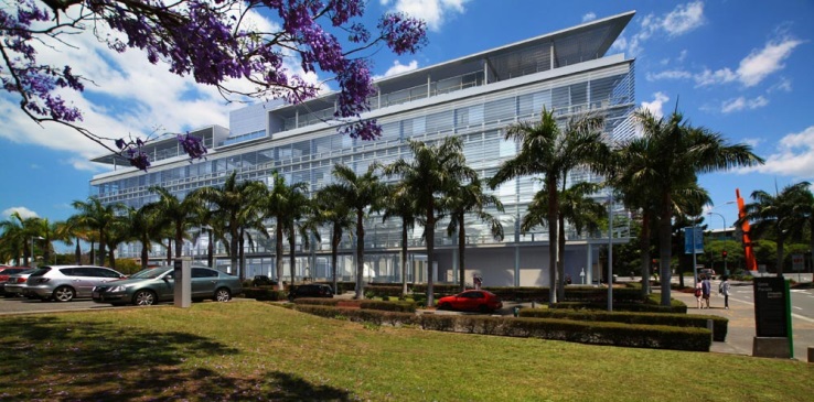
How the finished building should look.
The project comprises 3 Lots; Lot 1 – an upgrade to the existing plant room in another QUT building, to provide sufficient additional output for the new buildings; Lot 2 – a new, high tech, six storey building containing dance studios, study areas, research and support facilities etc; Lot 3 – the restoration of three heritage listed single level timber buildings and the construction of a single level building, all to house a visual arts facility. Ultimately the building will act as a hub for the hundreds of lycra clad hotties you currently find around Brisbane.
Environmental Issues. As an added complication, the site needs to achieve 5 stars under the Green Building Council of Australia’s (GBCA) Greenstar initiative, which places restrictions on the build in 9 areas; management, indoor environment quality, energy, transport, water, materials, land use and ecology, emissions and innovation. One of my tasks to date has been to ensure that the electrical cable schedule for the build complies with the PVC best practice guidelines – fortunately I had a visit from KY last week so I could draw on his vast knowledge of all things PVC!
Contract. The contractual setup has John Holland Group as the principal contractor under a construct only contract. The work is all being done by sub-contractors so John Holland Groups role is essentially coordination. At the minute, as we are still building the structure and not yet installing services, it feels like John Holland Group is just passing messages between the sub-contractors and the design consultants (via the architect and the project superintendent). I’m sure we will start to add more value when we start installing the services in the next few weeks.
Team Composition & Structure. As we are co-ordinators on the project, the team is a small one with just 4 site engineers reporting to a senior engineer, 3 site foremen who report into a site manager and a 2 man commercial team reporting to the commercial officer. The dynamic can be challenging at times as the structure has the foremen and engineers in separate reporting chains. There are frequent communication frustrations between the foremen, who seem purely interested in pushing the programme and getting ahead of time, and the engineers, whose responsibility is it to ensure adequate checks are carried out before each concrete pour and to ensure arse covering the paperwork is in order. Neither the organisational structure, nor the site manager (an ex-foreman), force the foremen to keep the engineers updated on programme changes. As such there will be an almost daily unplanned scramble to get inspections done and paperwork signed. My attempts to get both parties to update progress/changes on a whiteboard on a daily basis have made some improvement to this, albeit reluctantly on most parts.
Subcontractors. I will wrap up this blog with a picture I took at an off-site inspection of some electrical kit I went to. I’m not sure what the orange box in the background is, but the young lass in the foreground is the electrical design consultant. Not bad!
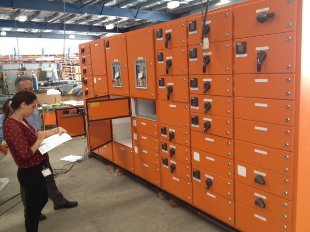
Main Switch Board Inspection
Social. It’s pretty rubbish out here as you can imagine. I’ll just post a couple of pictures of the horrors I have had to endure.
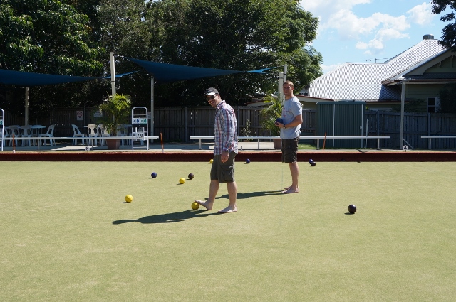
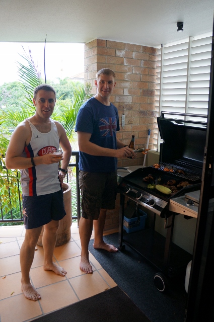
Playing bowls with Pete at my local club. Cooking shrimps on the barbie with KY.


Driving my Ute on the beach. The missus making me touch the top of a mountain!
I’m on leave now for a week as the site is closed for the week between Easter and Anzac Day, so will blog after the CI’s visit.
