Archive
Drainage tanks in slopes
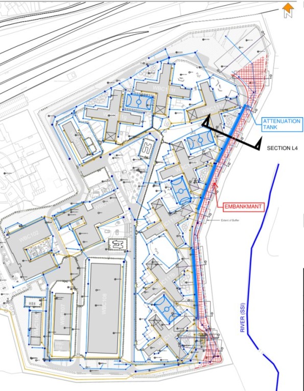
My latest Ph3 task is to coordinate the design of a reinforced slope with a surface water attenuation tank buried inside the embankment. Every part of my engineering judgement makes me think this is a bad idea – the challenge is to now engineer a solution that will work.
Background
The site lies on hill adjacent to SSI (a river and marshland). Two major risks with the sloping site;
- Excessive surface water run-off.
All surface water drainage requires attenuation to limit the discharge into the river. The redevelopment work will increase the capacity and size of the facility by 4-times the original.
- Major cut and fill exercise.
Project design specifies split levels and requires major cut and fill exercise to create plateaus for several large buildings.
Initial Design
Initial storm drainage design located attenuation tanks under sports pitches. This is an ideal scheme; large areas with minimal loading permits shallow excavations for large capacity tanks.
The Construction Phase Plan could not be achieved in unison with this scheme. Large laydown areas were required to facilitate the erection of multiple pre-cast concrete buildings simultaneously. Freedom of movement for heavy crawler cranes was integral to critical path activity. Any buried attenuation tanks would not have been able to handle these loads and the scale of temporary works to mitigate damage was not cost effective.
A large (350m-long, 6.0m high) retaining structure is necessary along the Eastern edge of the site to achieve level ground. Initial design concepts sought to utilise excavated Oadby Till (Clay) to produce a cement stabilised embankment.
Issues
Boundaries – Need to move the location of the attenuation tanks. The only available space where the tank could be buried deep enough to handle heavy construction traffic was adjacent to embankment.
Properties – Contractor is keen to use materials won on site to reduce costs (and claim some sustainability benefit). The clay alone does not have the capacity to achieve the 40-degree slope required. Confirmation of material strength following cement stabilisation can take 35+ days. This would not work with an already compressed programme.
Ground Water – A second design to reinforce the clay has been proposed but in an undrained state, the tails of geogrid would clash with the only available location of the tank.
Contamination – An underlying mudstone layer has high sulphate levels that are detrimental to cement stabilisation. Some of the boundary layers are ill-defined and risk of sulphates with the clay exists – further justification to reject cement stabilisation.
Options
My role is to understand if the following concept is achievable;
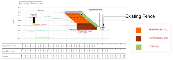
Major demolition works on site have generated a source of granular fill. This screened 6F2 could be used to form a steeper embankment and prevent a geogrid/tank clash due its superior characteristics. Preliminary calculations suggest there is insufficient quantity of this on site to form the entire embankment.
A hybrid embankment could be the solution.
Using drained granular fill to support the lower section of the embankment means shorter geogrid tails can be used next to the tank. The cut and fill clay will form the upper section of the embankment where the geogrid tails can extend above the tank. This maximises the re-use of material won on site.
I know others have looked at earth embankments – any thoughts?
Stadium Porn
After a week of button bashing, trying to understand why Tekla was spitting out mental wind loading values on a prison block steel frame design, the following came as welcome relief…
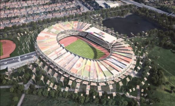
Fig. 1 2022 Commonwealth Games stadium artist impression
My phase 3 is with Arup and I am working out of their ‘campus’ in Solihull, Birmingham. Today the head of structures set the challenge of a concept design for the 2022 Commonwealth Games stadium. I wrongly assumed he was joking when he called everyone into a meeting room, handed out some rolls of tracing paper and declared “the architects arrive this afternoon, you have 30mins to sketch a concept for the new stadium, be prepared to present your scheme to the group and demonstrate how loads transfer to the ground”.
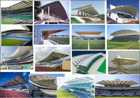
Fig. 2 Stadium porn
Obviously the architects are not coming until next week but it was cool to see the half dozen concepts get critiqued. We are not forecast to start developed design for a few weeks and there is still opportunity to take influence from existing stadia.
Has anyone been to a venue that impressed? The AAMI in Melbourne was used as a case study to showcase recent Arup success.
Please can you share your suggestions on here and I promise to credit you if it gets taken forward…
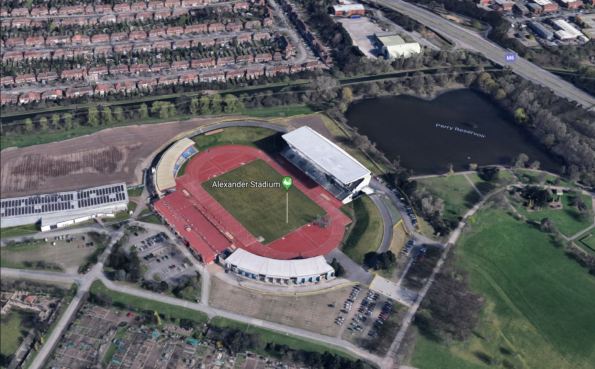
Fig. 3 – Google image of existing Alexander Stadium
Alexander Stadium will be redeveloped into a 40,000 seat capacity but has to incorporate the existing East Stand. Both the North and South stands will be de-scoped after the games to leave a legacy 20,000 seater.
Birmingham’s Alexander Stadium in £70m revamp for 2022 Games
3D pdf models
We are about to install a section of beams to support a Mezzanine floor level. The supporting structure is made from expLORe pre-cast walls (Laing O’Rourke’s own brand of twin wall). In the photo you can see the pre-formed pockets where the steel beam will bear into the 8m high wall at mid-height.
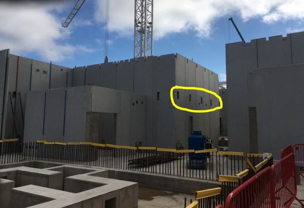
The pre-cast walls have a 16-week lead time for manufacture and so detailed installation considerations had to be made several months ago. In order to develop this, our on-site Digital Engineer modeled the installation angles the beams would need to achieve whilst on the crane hook. This check identified the need to oversize one of the pockets so beams could be ‘maneuvered’ into place.
The point of this blog is to showcase 3D pdfs. I had never seen this. Download the file on from this link.
It allows you to send 3D models to those without expensive software – an ideal method to communicate information where 2D drawings lack detail.
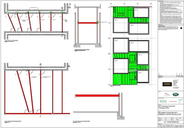
A very useful tool for the generalist RE when developing RAMS maybe…?
Controlling deflections in metal decks

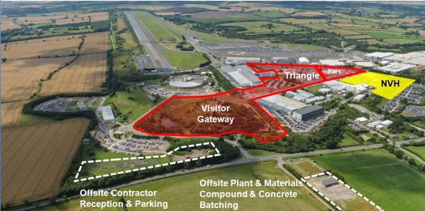
Fig. 1 Jaguar Land Rover – Noise Vibration & Harshness Project Roof Aug 2018
Steel and concrete interfaces on my project are causing us to ‘wave’ goodbye to the specified tolerances.
For an element of multi-story steel frame, we are forming composite floor slabs from metal decking and in-situ concrete. This seemingly tried and tested method benefits from the speed of frame construction and a reduction in material costs due to combined geometric performance. And yet, even with an experienced design team and contractor, the finished levels of our slabs wave up and down by ~40mm.

Fig. 1a Heat map underside of slab defelctions
A quick google search generates lots of information and warnings relating to level tolerances for composite metal deck slabs but the outcomes we have observed seem to surprise the project team.
Is anyone else using metal decking or aware ways to overcome problems with its use?
1. Tolerances
A regular 6m x 7m grid of columns supports a typical arrangement of primary and secondary beams.
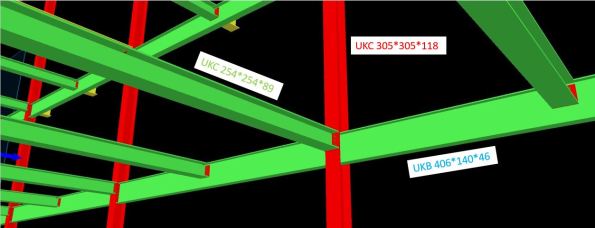
Fig. 2 Screen grab of model with slab removed
Table 1 – Steel Frame Elements
| Element | Size |
| Column | UKC305*305*118 |
| Primary Beam | UKB406*140*46 |
| Secondary Beam | UKC254*254*89 |
| Metal Deck | ComFlor 51+ |
The designer produced a tolerance specification, in which they confirmed deflections should not exceed the lesser of span/180 or 20mm (in accordance with UK National Annex to BS EN 1994-1-1 and BS5950-4).
In our frame; 7000 / 180 = 38.8mm > 20mm therefore max δ = 20mm.
As built surveys confirmed that the secondary beams (UKC254) were consistently deflecting ~20mm under construction loads only. This was also true of the primary beams (UKB406).
The greatest deflection is highlighted by the sketch in Fig. 3 and occurs when the secondary is connected to the primary at mid-span. The 20mm tolerance has already been used up and the subsequent deflection in the secondary means the combined deflection at mid-point of the slab is ~40mm.
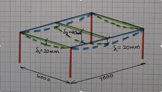
Fig. 3 Steel frame bay deflections
2. Method
The concrete pour on Level 1 was poured to a level. An inexperienced graduate engineer was convinced by a construction manager that this was the correct methodology. All drawings indicated that slabs on metal decking should be poured to a thickness to prevent ponding of concrete.
As more concrete was poured to achieve the correct level, the deflection increased under the additional self-weight loading. This cycle continued and resulted in a slab 40mm thicker than design at mid-span.
We felt this error in methodology was the root cause of the excessive deflection. For Level 2, particular attention was applied to ensure the slab was poured to a thickness and yet similar deflections were observed (Fig. 4).
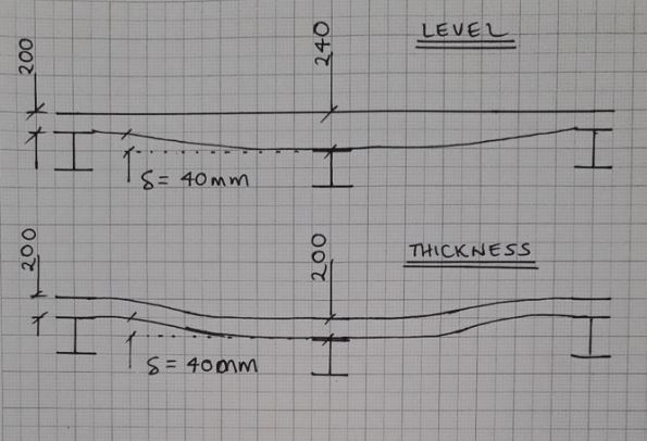
Fig. 4 Slab profiles
3. Future options to limit deflection
This had led me to believe that the sections have been under sized in the design. The slab on Level 2 is due to be a plant room and has gullies positioned adjacent to columns – if any of the plant leaks, water will not run uphill on our wavy slab!

Fig. 5 Finished level variation in slab pour to thickness
In a report by the ASCE[1], four options to reduce deflection in composite metal decks are offered;
- Increase section sizes
- Pre-camber members
- Place additional concrete
- Back propping
Given that our frame is already built, the only option I think we have is to install temporary works to back prop future slab pours.
I welcome any other suggestions…
Will we also need to increase the reinforcement in the slab?
Should we allow for more deflection once variable loads are applied?
______________________________________________________________________________________
Updated to show more recent as-built heat map of finished level of slab.
Majority of LHS was poured to a level with clear results +/-9mm.
RHS and bottom left all poured to thickness with -40mm under secondary beams.
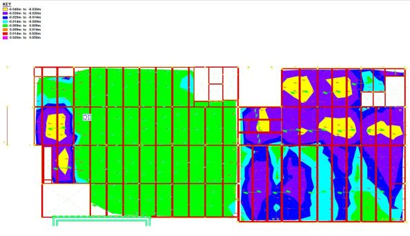
Fig. 6 As-built finished levels
[1] https://www.concreteconstruction.net/_view-object?id=00000153-8c44-dbf3-a177-9c7d96b40000
Jaguar Land Rover – Noise Vibration and Harshness Project
Keen to hear some thoughts on the structural design vs. buildability of a concrete-steel connection detail that has been generating much discussion throughout my whole project team!
–
Context
Jaguar Land Rover are spending big in their heartland here in the West Midlands. The main Research and Development site is very close to MOD Kineton in Gaydon. The former British Leyland campus has been developed from an old Vulcan bomber runway into a series of test tracks and supporting facilities.
Laing O’Rourke have close to £400m of work and I am part of their Expanded Structures engineering team on the Noise, Vibration and Harshness (NVH) project.
A last minute change of contractor by the client, and no extension to the delivery date means this D&B contract is running very hot.
–
In order to outmatch the German and Japanese markets, JLR want to be sure they have increased build quality in their cars. For this a new NVH facility is required that will resemble a high-tech laboratory for cars. 30 No. individual testing cells will see vehicles on rolling roads pushed to their limits within isolated and unique environmental conditions.
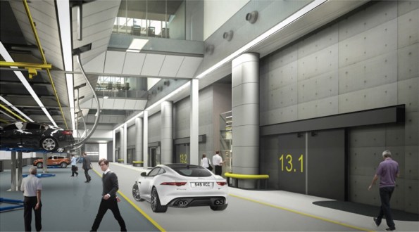
Ridge Consultants have designed a ‘box within a box’ concept to ensure the vibrations from testing are not transferred to the structural frame. LOR are using their own pre-cast system called ‘Twin Wall’ to form the cells and a steel frame will house the whole facility with internal roads and office space.

Twin wall is a double skinned pre-cast system in which a cavity is filled with concrete once positioned on site. There are a host of quality and logistical benefits to using this method but it now gives us a buildability challenge with a concrete-steel connection.
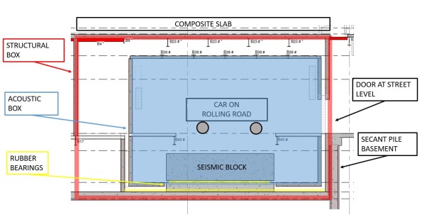
Typical section of a vehicle test cell.
Large RC seismic blocks sit on a bed of rubber bearings. The rolling road plant is fixed to this to prevent excess vibration transfer to the structure.
Structural box is formed from twin wall with composite slab roof.
Acoustic inner box is also formed from twin wall with composite slab roof formed inside steel webs to create flush finish.
Build sequence is;
- Lay rubber bearings
- Cast seismic block
- Erect Structural Twin Wall
- Cast Acoustic base slab
- Erect Acoustic Twin Wall
- Fix steel beams
- Cast composite roof slab
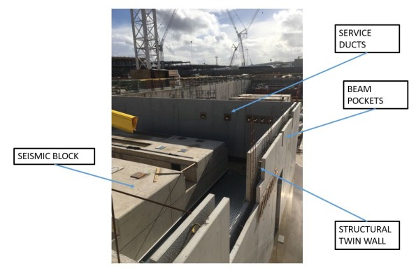
So far we have just positioned the first set of structural twin wall. In the progress photo you can see the service ducts and beam pockets that have been formed in the pre-cast leaf of twin wall.
The Acoustic wall will sit in between the structural wall and the seismic block.
–
Issue
Some of the spans are 14m and so large UKB 1016 x 305 x 272 have been pre-cambered. The structural engineer at Ridge has designed the steel primary beams as a pinned connection to allow the camber to drop out upon loading of the wet concrete composite slab.
As the designer didn’t understand the build sequence of the twin wall, they assumed these beams would have full bearing of 145mm at either end upon loading. However, the top infill of twin wall is typically cast at the same time as the composite slab it supports.
The designer proposes a shuttered pocket forming a void within the infill concrete pour to top level of wall. Packing shims are then placed before landing the beam and adding a layer of non-shrink grout. Flexible boarding behind the beam is then positioned and the remainder of the void infilled with more grout. All this shuttering and small grout pours are proposed to be at the top of twin wall panels 7.7m above ground. It is not practical for this detail to be implemented on site. We have in excess of 300 of these concrete-steel connections to form and that creates a significant amount of repeat visit, working at height activities. We seek a solution to reduce this by refining the detail.
–
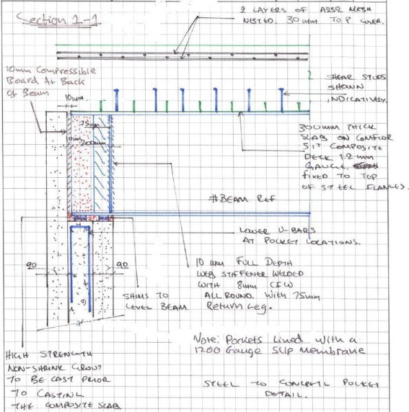
Our concept is to land the steel on a full width shim that is fixed with resin to the outer leaf of the twin wall with the cavity only partially filled. The end of the beam would be wrapped in a flexible membrane to allow the pinned connection to form once we pour the composite deck and final lift of twin wall infill as a single pour.

We are waiting for the structural designers to check if the bearing in this case is acceptable as in the temporary state the 90mm leaf of twin wall carries the full load. See my concept below;

I ran some numbers so I could compare with their results;
Beam
UKB 1016 x 305 x 272 = 272kg/m
WL/2 * 1.35= 26kN
Slab
Wet concrete = 26 kN/m3
Depth = 0.3m
Beam centres = 4.0m
26 x 0.3 x 4.0 = 31.2 kN/m
WL/2 * 1.35 = 295kN
Construction Loads
Q = 1.0kN/m2
WL/2 * 1.5 = 42kN
Total Bearing
Beam + Slab + Construction = 363kN
| Bearing (N) | Shim (mm) | Area (mm2) | Pressure (N/mm2) |
| 363,000 | 145×305 | 44225 | 8.21 |
| 90×305 | 27450 | 13.22 | |
| 60×305 | 18300 | 19.84 | |
| (60×60)x2 | 7200 | 50.42 |
Concrete is C40/50 (50N/mm2) and so by my reckoning, even if we place a 60mm shim beneath the steel, the bearing on the twin wall leaf would be less than the capacity of the concrete.
- Does that bearing capacity sound right?
- Any other ideas how we could de-bond the steel and so form a pinned connection whilst seeking to minimise work at height?
–
There are other interesting challenges for us to overcome that I might blog about in time;
- Passing services between the test cell and main structure without transferring vibration. (See my detail above with initial concept).
- Calculating the amount of settlement to allow for in the rubber bearings so we don’t set the road level too high / low.
