Archive
Design office blog 3
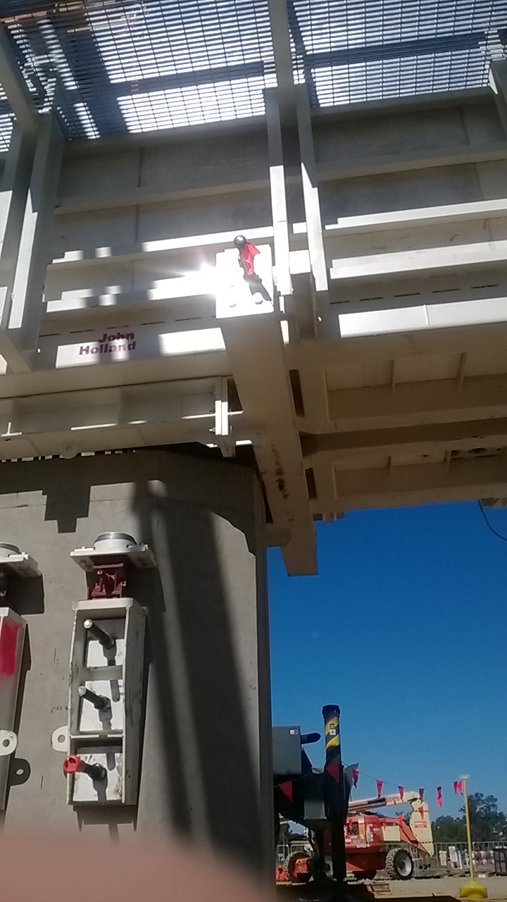
Submitted a tender to ICC (that I was bid leader for)
This was a request for tender that came through from a panel agreement that Jacobs have signed up to. The proposal was a fairly small one, with fees in the region of $30,000. It involved the checking of a preliminary design that the council had completed themselves, including some computer modelling, plus the design of some discrete elements in the stormwater harvesting scheme. This all sits within a larger flood mitigation project (outside of the scope). It was nice to be given this to run with as I’ve worked on a number of proposals now, but only concerned with the civil aspect of these larger projects. It allowed me to go through the review process and complete the tender documentation, helping to understand the elements that I’d only read about previously. This included everything form assessing the brief to submitting CV’s of the team that would complete the work, arranging the insurances and finally getting sign off from 2 of the directors (plus lots of other tasks).
I looked into the panel agreement a little further, as I’ve not encountered it before. The Local Buy panel is essentially a 3rd party organisation that matches clients (from local government) to design services and other service providers. There is a list of agreed rates that exist between Jacobs and the panel. In practice they just send out the requests for quotation to the companies on their list. Then they add a 5% fee. I can’t really see what value they add in the current market. The rates agreed were far above what is currently the market norm.
Completed stormwater sizing for the 50% design on Amberley RAAF base.
This was a small bit of design work to help out the engineers working on this project. First I worked out my design storm and the rainfall intensity, the Qld Urban Drainage Manual (QUDM) was the local standard to follow (as the land is owned by Defence they don’t have to adhere to local legislation, only federal, but they tend to follow it out of courtesy). I calculated my run-off areas from the CAD sketches, and picked some inlet positions. I took the design through to the sizing of pipes and inlets (this involved checking the flows captured in each inlet and what would carry on to another inlet).
Cost estimate for accommodation relocation.
This involved the client relocating dispersed accommodation assets to one location. The location to be removed has been sitting empty for some time. The new location was originally planned to be much larger, but was scaled back prior to completion. However all infrastructure was sized for the full camp (2500 men). The camp bore many similarities to expeditionary infrastructure, as each location had their own water treatment and sewerage treatment plants. Power was from the main grid and stepped down to 33KV where it came on site. There were then a series of HV and LV loops around the camp. The water and sewer mains were fairly simple to tie the new accommodation units into. I then received a rapid lesson on the comms and electrical infrastructure that would be needed from the team downstairs. I was just able to follow the lingo with the electrical kit, but started to get a little lost when it got to the comms. It turns out that each 4 man “donga” has fibre to it. It is then converted to copper for the individual rooms. I scribbled down lots of notes about the number of head end FOBOTs required and how the 144 core cable ran in a big loop from the main comms room. Each laundry unit was where the 12 core loops to the dongas were split out (there was another FOBOT here). All very interesting stuff I’m sure.
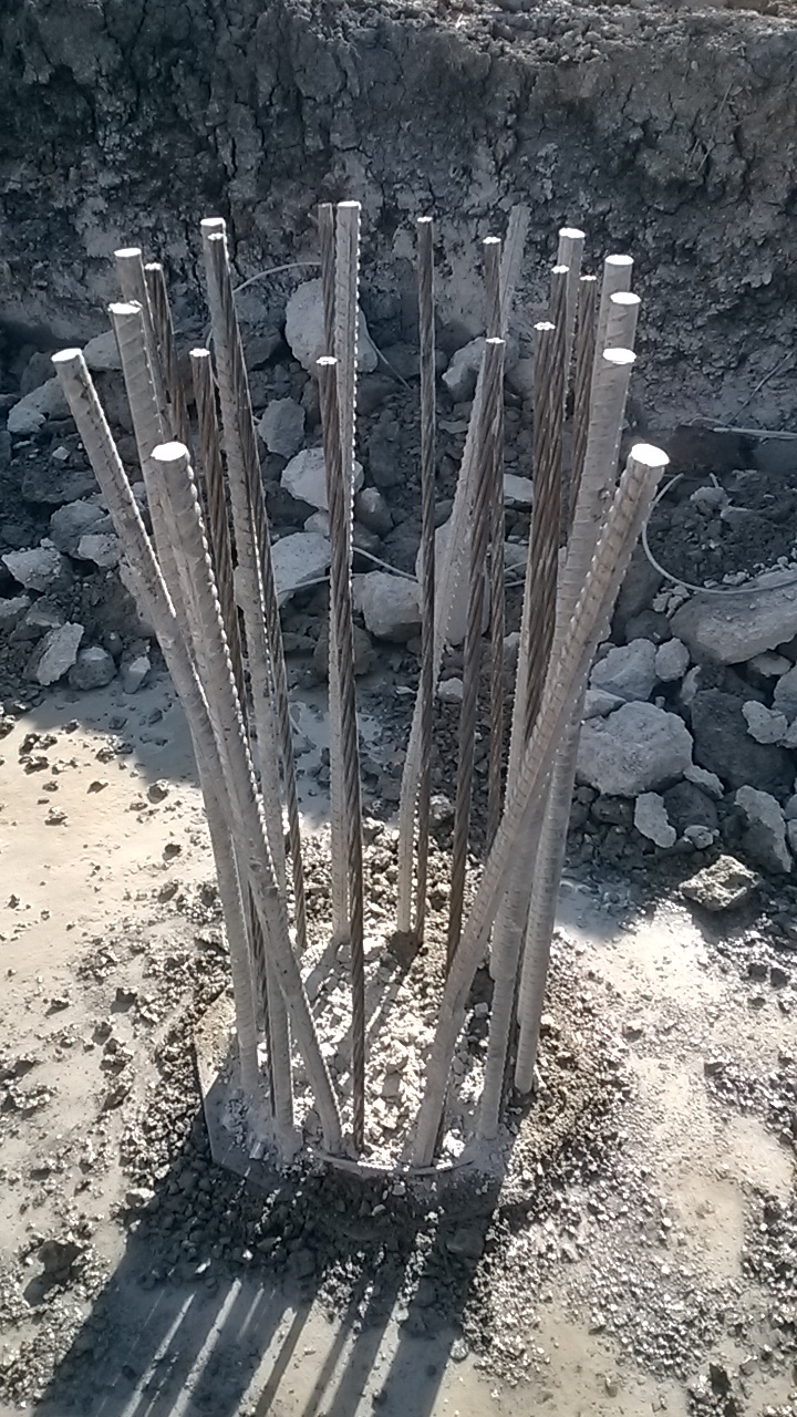
I got one of the drafters to put some quick sketches together on CAD. (see below)

The client was keen to know the cost as if it was below a certain value the move could be done as part of their operational budget. If it was too expensive it would fall to capital works and wouldn’t be possible in the current economic climate (commodities are currently suffering).
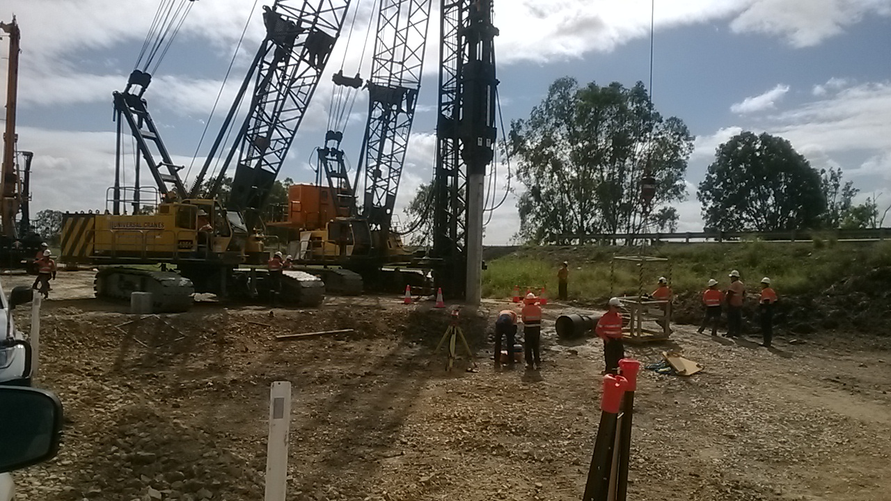
Recce to Melbourne (Puckapunyal) for a crossing design/assessment.
This turned out to be both a very frustrating project and very informative. At the start this sounded like a great little task, involving a free trip down to Melbourne. However I only saw Melbourne airport before heading North to Puckapunyal Training Area. This is the home of the Australian Army school of Artillery and their school of Armour. There is also an experimental weapons range tagged on the side for good measure. The background to the project is that Jacobs are managing the maintenance contract for the range. This year there was an underspend in the budget, so they are looking to squeeze in a number of tasks that were further down the priority list. On the training area are a number of crossings that have had their MLC downgraded significantly, see the photo below (looks suspiciously like a non equipment bridge). The aim is to install some new crossings to MLC 110T (wheeled). There is an existing design template that they want followed for these new crossings. Three existing crossings have already been built following this template on the training area and the client is happy with this style.
I was given the previous crossing drawings and the calculations that went with them. My task began as a review with some sizing of the culverts within the design (after finding the catchment size and calculating the design storm flows at the crossing points) On return to Brisbane I confirmed what I would be able to do for the team in Melbourne and set about deciphering the calcs. I completed my own check calcs in parallel to AS5100 (the Australian Bridge standards), the pavement was designed to a technical note published by the Cement and Concrete Institute of Australia.
Lessons learnt
Write down all thinking when doing calculations. It was really difficult to interpret this other engineers thought process. I am using educated guesswork to figure out why he selected a specific span to design to – it doesn’t match with anything in the design. It could also be old calculations from a previous job that were never updated – I just don’t know.
Understand clearly what you are being asked to do before starting a project. If the aim had been made clear form the outset, that a set of design drawings that could be issued for construction (IFC) were required, time and effort could have been saved. While I clarified what I was doing with the team in Melbourne on my return, they never stated their need for IFC drawings, or for any material to go outside of the company. This could be my own ignorance, but with hindsight I think they were after a quick and dirty, “she’ll be alright, just go build it”.
Unwillingness to move outside of comfort zones. This could be interpreted as people adhering strictly to the codes of practice and only working in areas that they are competent in. I see it as people not wanting to make the effort and take responsibility for a project. Going to other specialists for help when those unknown areas arise. This was put in the “too difficult” file by many until I pushed for the job to be taken. This could be due to the narrow field, but depth of knowledge many seem to develop. Only a few of the older engineers seem to have much in the way of cross discipline experience. Has anyone else encountered this? Is it more prevalent in the larger consultancies?
Runway Blast Protection
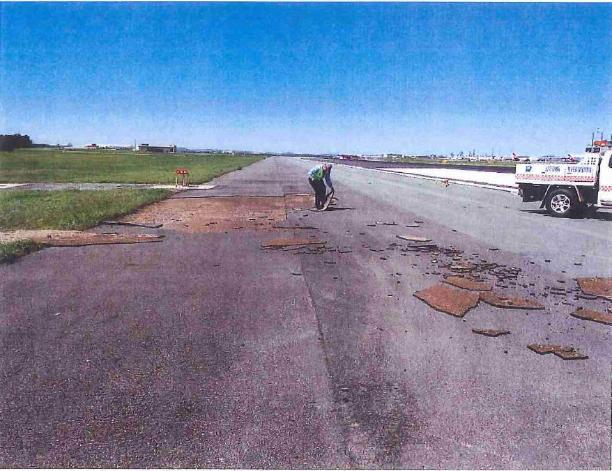
This is less of a blog post and more of a plea for information. Does anyone have any knowledge or experience of blast protection on runways? There is a job coming up at Brisbane International Airport for rehabilitating the protection on the main runway, and I’ve somehow found myself helping on the tender. There are severely restricted working hours that have been arranged out to 2016. The work window is only 4 to 5 hrs long. My initial understanding is that the blast protection is just a pavement with a reduced thickness, as planes will not traffic it. As I take it, the added complexity comes with the reduced working time impacting on what materials will be useable. They would have to achieve sufficient strength before the runway opens and planes start to land again. Any of the surface tearing up wouldn’t be good if it ended up in a jet engine. The picture below shows damage that happened previously and led to the shutdown of the runway – this resulted in massive disruption to flights and I’m sure some hefty costs to the airport operator.
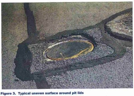
The next couple of photos are from a recent inspection of the runway and show electrical inspection pits that are in poor/dangerous condition.

Any first hand experience, or knowledge from previous projects would be greatly appreciated!
The Joys of Office work
So I’ve now settled into the Jacobs design office. I’m starting off in the civil infrastructure team. The main things they deal with are bulk earthworks, roads and stormwater (drainage). So far I’m straining my brain in trying to remember all the stuff we did with Richard before disappearing off on Phase 2!
There are a few existing projects on the go, but most of what I have been doing recently is new proposals. These are either in the tender process or pre-tender.
Jacobs structure has marketing and sales sitting separately to the rest of the company. They seem to focus on relationship building with a number of clients – all in the hope of winning work before it goes to tender. For private clients I can understand this, but for government or defence clients that have to go to tender I’m not sure how beneficial this is? The hope is that they will be asked to complete the prelim designs for a client, then when the invitations to tender are sent out they are already one step ahead of the competition. Despite my scepticism it seems to work well for them. This year the infrastructure group in Brisbane have won $50 million of work from one client (the department for transport and main roads). This is 49% of the total revenue for the Brisbane office.
The company separates the early stages of winning work into three parts: the opening, middle and end game. To put this in context of a project timeline, the tender decision is the last part of the end game. There are some flowcharts to guide people through this process (see below – handy for new people like me). The middle game decides the go/no go in pursuing the work from the client. Prior to this a SWOT analysis will have been completed on the Jacobs bid, but also one that looks at the competition.
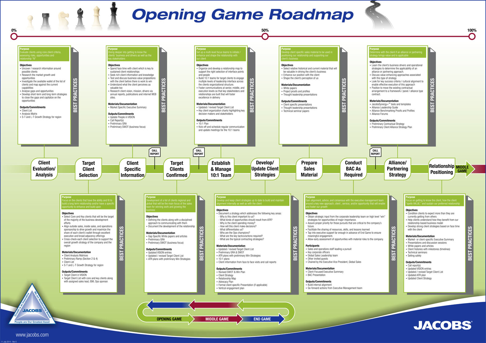
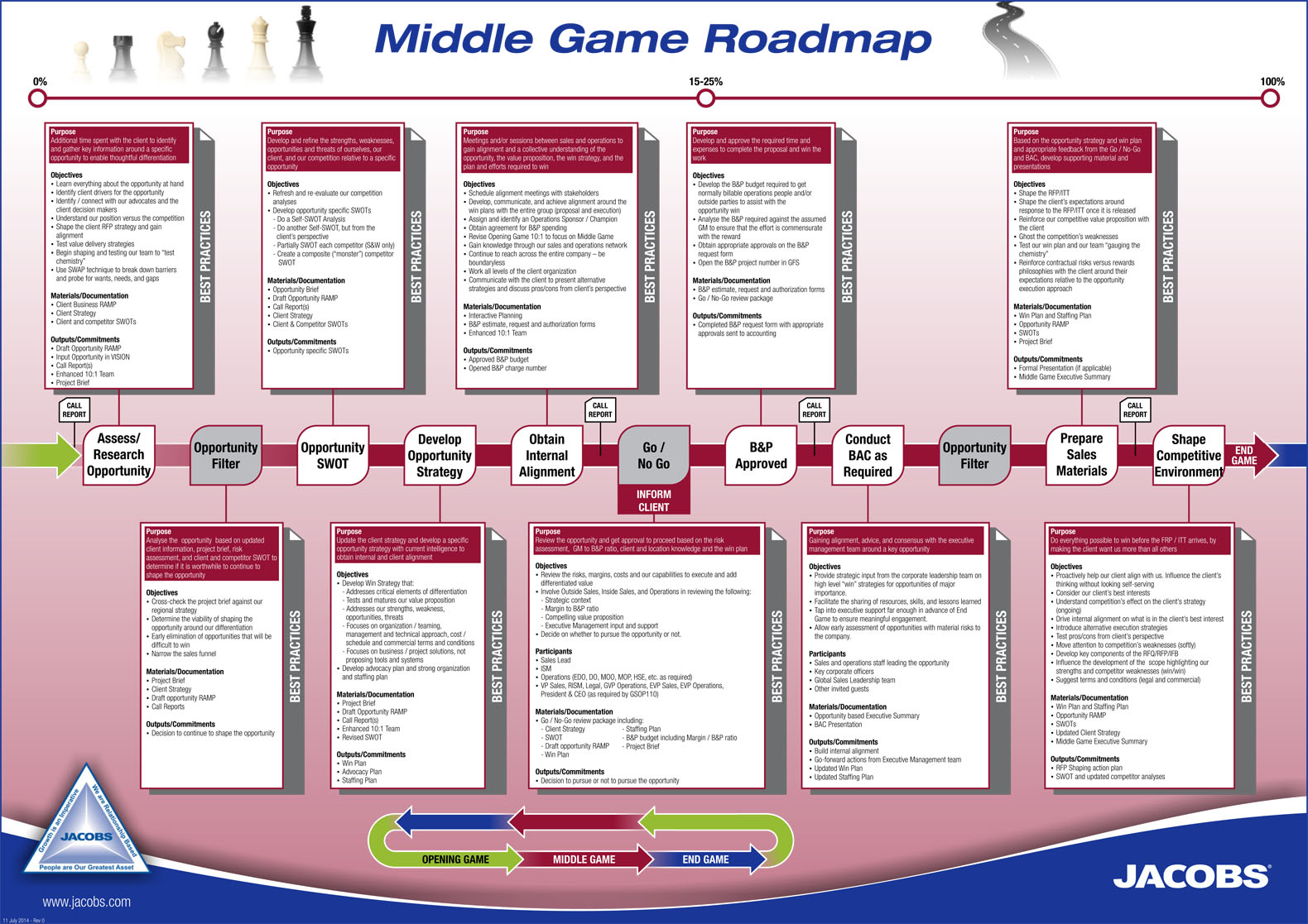

There is a surprising burden of paperwork that has to be produced during this evaluation process. I can’t help thinking this is a lot simpler in a smaller consultancy – is anyone able to comment? Is it equally paperwork heavy in the likes of Arup?
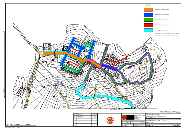
Most of what I’ve been doing so far is related to the early stages of bids and tenders, or so I thought (but these are in the middle and end game of the Jacobs initial process). There are 2 defence related bids of one and one health centre. The defence work if for the construction of an Urban Operations Training Facility (UOTF) and another Explosive Hazards Training Area (EHTA). Both are small in value and they are both located down near Sydney. This week the decision was made to “no go” the Holesworthy training area on the grounds that it wouldn’t have been profitable without winning the larger bid for Wide Bay. Too much risk I guess. The concept for the Wide Bay training area is shown below. The different colours denominate road types and widths.
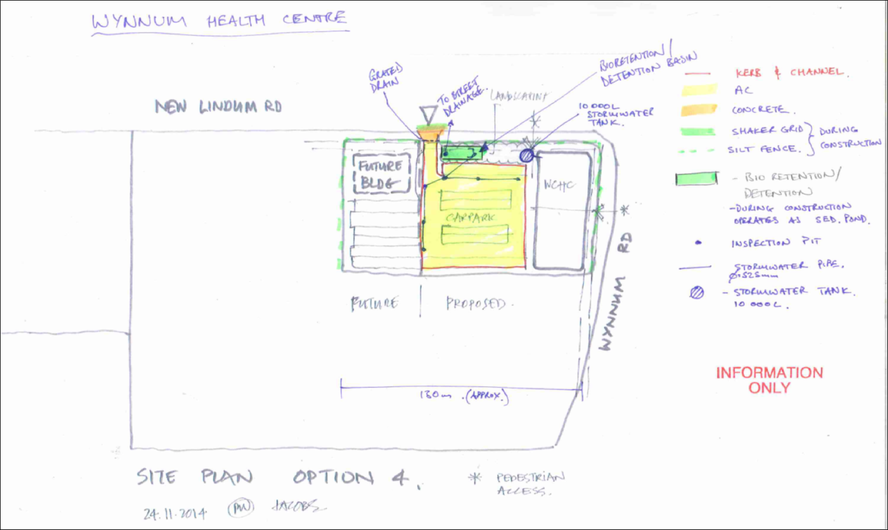
I’ve been focussing on the Health centre this week and getting together information to allow the contractor to complete the pricing for his bid. I’m probably starting to go a little further than I should at this stage, but I have the time to do this before the other projects kick off. I’m also compiling the cost and margin tracker for the civils team that will work on it. This will allow me to put forward the fee for the civil works. There is also a list of assumptions, inclusions and exclusions to submit (even though it is very early in the design process). See below for my first iteration marked up on the architects concept. This has progressed a little, but should give an idea of what I’m doing.
Its safe to say I’m getting some good experience logged towards B1 and C5 in the spec. Depending on the outcome of the bids there should be a number of workshops with the client and the other teams to work on value engineering. I’m also sticking my beak into the contract arrangements and I’ll be pestering the legal team in the new year. I’ll look to expand on what happens after the “end game” in my next blog.
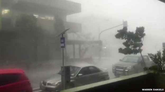
It was a bit stormy over here last week. It made the cycle home a bit interesting.
What happened when I left for holiday
There were 3 main noteworthy occurrences when I was back in the UK for my 3 weeks of summer leave.
Pier 2
The columns on pier 2 were poured and the bracing was not installed correctly (as per the designers drawings). My site engineer had the drawings with the clear notes on them as to where the bracing should have been. However the leading hand convinced that it would be fine not to follow them and that it wouldn’t budge. This was not the case. One of the props holding the form in position failed and buckled during the pour. This was only noticed after the pour and no effort was made to try and fix this. The 2 columns needed to be poured on separate days (unlike the planned one day) as the 9m long vibrator got jammed in the reo at the start of the first column. There was no mechanical 9m hose to replace it, only an air vibrator (which has a larger diameter hose and head, meaning it is more likely to get jammed). The pour continued with this replacement and the damaged vibrator was cut off and left in place in the column. I say it was cut off, but what really happened was they hooked a crane up to the hose and tried to pull it out. That only succeeded in snapping the hose off. When I returned and saw the columns there was a noticeable slant in it. This was confirmed by the survey of the columns. The contract is very clear that the allowable tolerance for this type of element is +/- 25mm and at 57mm is well out.
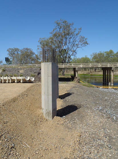
I checked the formwork system and came up with a way to make it work, even though there was 65mm difference between the 2 columns. However it is up to the clients rep whether they will accept this. They are well within their rights to have the column demolished and redone correctly, however the rough estimate is that will cost around $100000 (all paid for by JHG). To make matters worse the first 3 spans of the bridge depend on span 2 being lifted in by 2 cranes sitting on either bank (one 350t and another 250t). So spans 1 and 3 can’t go in till span 2 is up. By not being able to pour pier 2 headstock the whole sequence is delayed. There is also the added pressure that the 350t crane is only available for a small window. Outside of this we will need to find another crane, which will cost much more to get on site. I made sure that the bracing on pier 1 columns was much more robust, it meant the pour was delayed by a day but both columns were well within tolerance so it was worth it in my opinion.
Broken pile
The piling rigs have now moved onto bridge 2 to start work, having crossed the Bruce highway during a night time road closure without incident. With the end of piling on bridge one this was a suitable time for a handover to another engineer who was initially only responsible for the bored piles and retaining wall. With everything handed over I was rather amused when on second pier of piles in bridge 2 they managed to snap a pile.
The clients rep blamed us, and we blamed unforeseen ground conditions. There was no-one from the clients team on site at the time, yet they are still claiming that the piling subcontractors “pulled the pile”. For those that don’t know the term, when driving a pile they can have a tendency to deviate from the vertical. In the early stages of driving some minor corrections can be made, but once a decent length of pile is in the ground any attempt to “pull the pile” into position can damage and even break the pile. To back up our case we have over 800 piles that have been installed as per our sequence without incident. I’d like to think that it was my steady hand on the tiller which stopped any piles breaking, however that is merely a happy coincidence. The next step is waiting for direction from the client. Any action prior to this could be a waste of time. Looking at things the way they are I see 3 possible options open:
1) Ignore it. Cut the pile off below the blinding level and don’t tie it into the cap. This requires the designers to go back and look at what support/resistance the pilecap as a whole needs to provide. All the other piles in the pier are well over capacity. The steelwork in the cap would likely need to be redesigned to ensure the forces are transferred away from the gap of the broken pile.
2) Use it as is. Use what capacity there is in the broken pile and tie the pile into the cap as though there was nothing wrong with it. This would also need the same checks as option 1, as the capacity of the broken pile would be unreliable over the lifespan of the bridge. In effect its just option 1 but not wanting to waste what has already been driven.
3) Drive another pile adjacent to the broken pile (towards the centre of the pier). This would be within the 3xD that the piles are currently spaced at, the steelwork would need to be redesigned in the pilecap and access to the position for the piling rig would be difficult (but not impossible). If the pile did break because of a large discontinuity then this pile may too also get damaged.
The Spaniard
Soon after my return there was a visit from “the Spaniard”. This is one of the executives from Groupo ACS who own Hochtief, Hochtief in turn own Leighton holdings, they then own John Holland. So lots of the executives from John Holland were on site to wander around. It was all to do with cashflow and why we were going over budget. His opinion/answer was that we needed to secure our revenue streams before acting on something. The example used was the large pile offcuts that we have on site. The additional cost for these offcuts should come from the client (in his opinion) as the piles are barely making it into the underdrive allowance. My simplistic understanding agrees with him. You would expect that most piles would be at the design toe depth, or that the average for the site as a whole would be close to the design toe (with some in the underdrive and some in the overdrive). However the vast majority of piles are sitting 3m above that design toe. My guess is that the designers were overly cautious in their design, and to reduce the risk of not reaching capacity, went for longer lengths of piles. By reducing the design risk they have created more work for the contractor, but at least there is plenty of capacity in the piles! The recent development that has come as a direct result of the claim for the pile offcuts is the direction from the clients rep that all piles must be driven to design toe. This is adding extra time to each pier, and could potentially damage the piles. The size of the hammer is such that were it used at full drop height the piles would likely split. The PDA gauges were connected after the split occurred to confirm it, and to give an indication of where the pile was damaged (roughly 3m below surface).
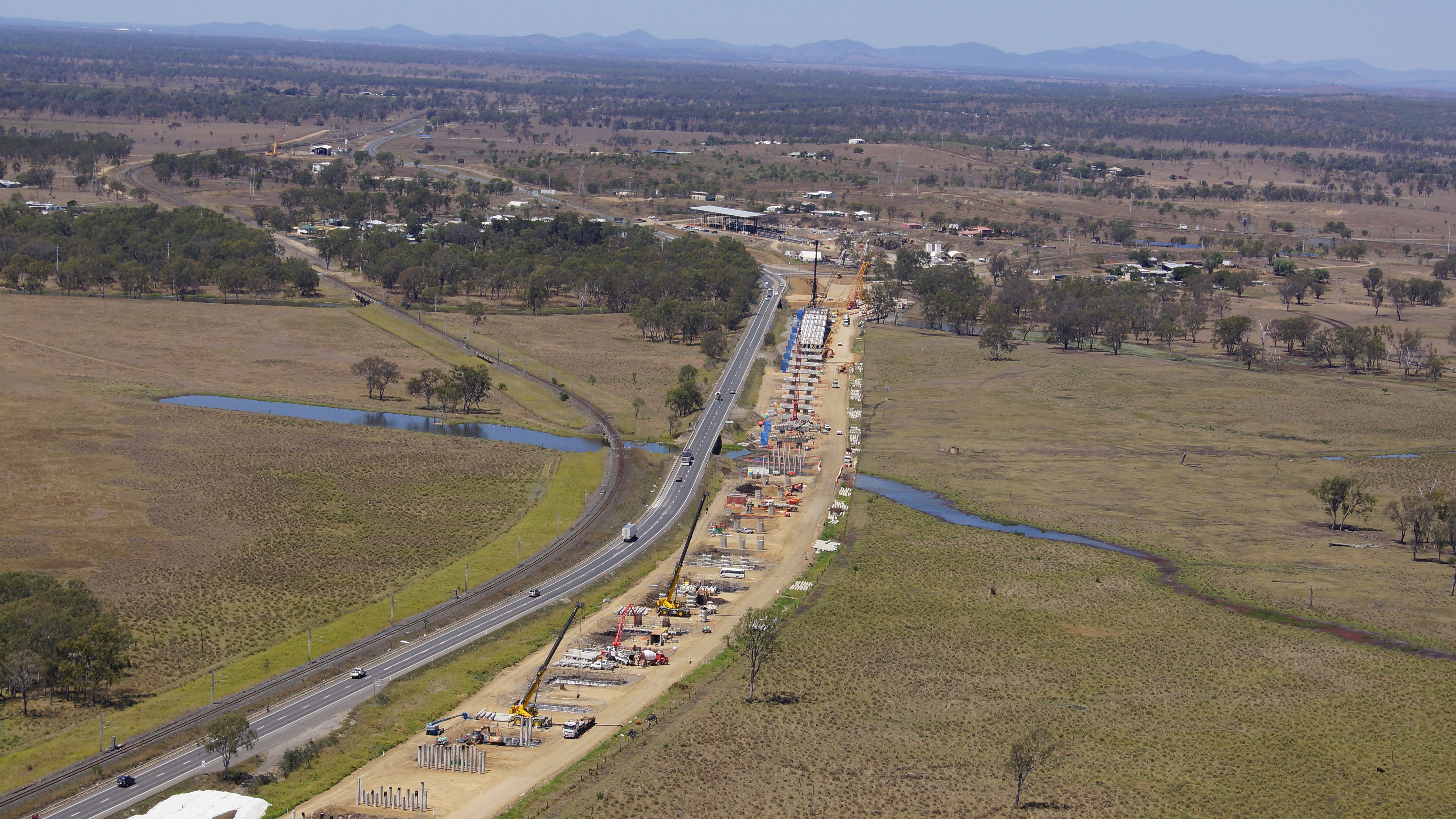
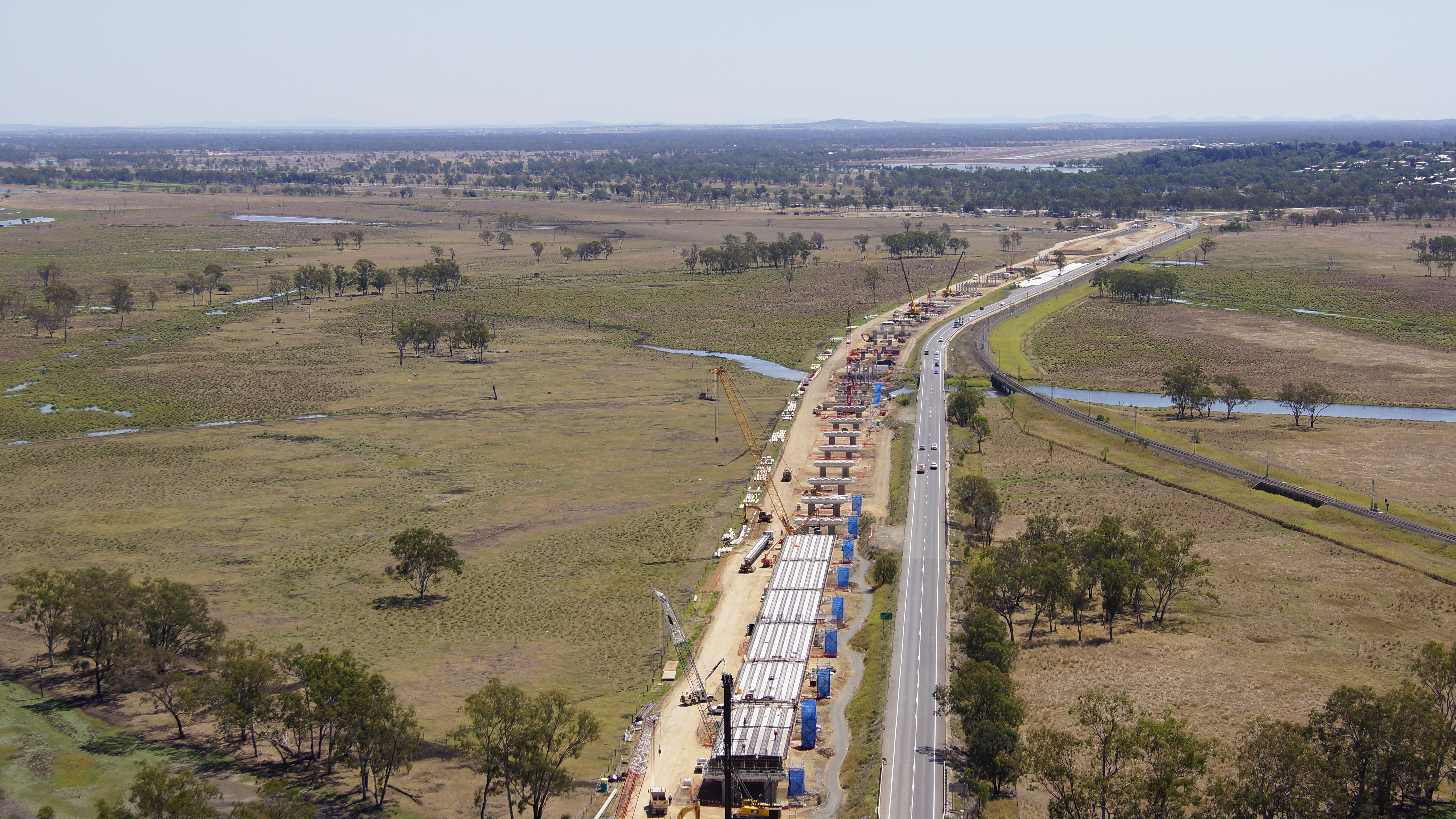
I’ve also got my hands on some aerial shots of site that were taken just before I went on leave. They’re worth waiting for the page to load to have a look at as the detail is pretty good.
Fixing mistakes
I’ve mentioned in a few comments there are now getting to be a number of repairs that are needed on parts of the substructure. With a bit of luck what I’ve learnt may help anyone else that ends up with similar issues in the future, or feel free to tell me where I’ve gone wrong!
Problem
They fall into 2 categories – damage after the works and incorrect procedure resulting in remedial action. There are a number of causes for both starting to happen in my opinion. Initially there was a big push to get productivity up, then there was the need to reduce costs. This started with reducing the numbers on site and we are now in the situation of reducing hours for some of the work groups. This means moving people about the site and workers jumping from one crew to another. This leads to procedures not being followed and a new learning period if the crew changes and the new bloke gets left to stay back and finish off the pour. However I digress.
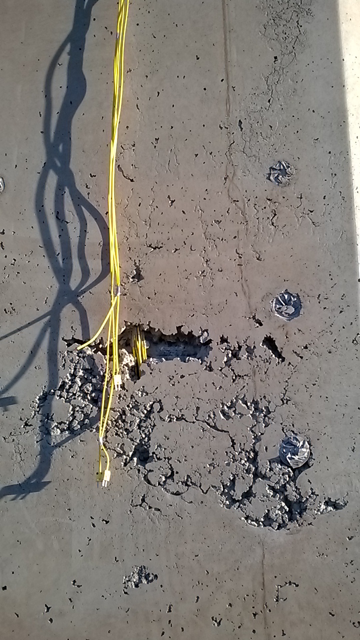
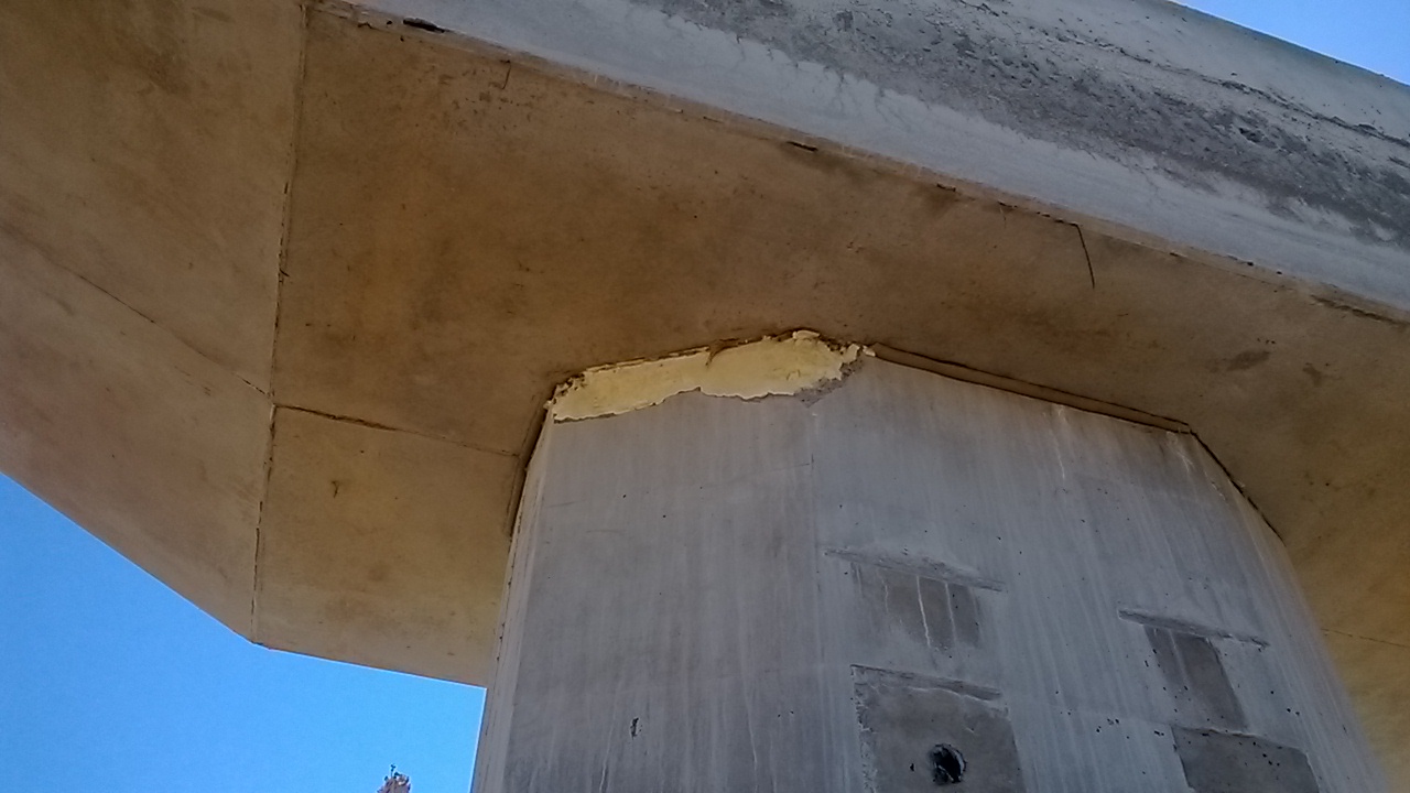
The photo below shows the damage done to one of the pedestals on pier 10. The workers that stripped the formwork said nothing about it happening, and the concrete that broke off is sound, as is the concrete remaining on the pedestal. The formwork could have been removed at an angle, or there could have been a lack of form oil on those sides. I think the most likely cause is that a sledgehammer was used to help persuade the forms off, not that anyone is owning up to that.

Solution
To fix the problem the concure had to be removed, which proved much more difficult than first thought. Most curing membranes on the approved list for transport and Main Roads degrade after a period of 6 to 8 weeks (normally under UV light). However trying to remove the membrane before this isn’t that easy. High pressure water blasting isn’t effective. There are a lot of environmental controls involved with sand blasting (not to mention the cost involved). That only leave mechanical removal, or in this case a man scrubbing it off with a scouring pad fitted to a buffer. The cost of this work now, however is preferable to doing the rework later in the program (after 6-8 weeks) as the girders will have been landed and cross girders poured. While it is still possible, the access is severely restricted and will take much longer to perform.
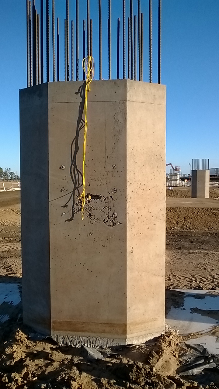
Back to the solution to the breakages. The concrete had to be cut out to a depth of 20mm and then broken out to expose the reinforcement. There needed to be sufficient room behind the bars to ensure that the aggregate flowed behind the bars and made a strong bond. See photo above for what it looked like after being formed up. After this the area was cleaned out and dampened (but no free water on the surface.The next stage was coating the steel and concrete in Nitobond AR. This is a 2 part epoxy that is designed for bonding fresh concrete to old concrete (or concrete that has already set). I did consider using other products such as Renderoc HB70, however the client preferred using a concrete patch for the aggregate component. The other side of the pedestal had no exposed reo and so a small bar of reo was chemset into the pedestal to provide a sound anchor for the new concrete. IT was a different 2 part epoxy used for this – Hiti have RE 500 which is very common, but expensive, we used Power fasteners PF PRO but there is also a chamset series of products by Ramset. The combination of the steel as an anchor and the nitobond should stop any problems of the repair falling out in the future – as due to a different batch of concrete being used there have been instances of repairs just falling out, with the differential thermal expansion of the two mixes.
The Other Problem
The issues with our own procedures not being followed have led to a different set of repairs. On the headstock the construction joints for the pedestals need to be prepared the day after the pour. To make the preparation of these joints easy we apply Rugasol (made by Sika) after the pour is finished, there are other equivalent products by Parchem, Ramset etc that could be used. Using this makes the greencutting the following day much easier and can give a very good clean construction joint. The rugasol should be worked into the area of the joint (it can be sprayed on, but this doesn’t work with the curing method we are using). If it is not worked in then when the damp hessian is placed ontop and flooded with water the Rugasol can spill out over the entire headstock. This has happened a couple of times, and while the impact isn’t dramatic it reduces the quality of finish on the surface. The inspectors have issued an NCR and stated that they want the surface dressed to achieve a class 2 finish – this is well within their rights as that is what is in the contract. They went a step further though (too far in my opinion) and have instructed us to coat the surface with Xypex Modified. This is a waterproofing sealant that is normally used in marine environments, reservoirs/dams and swimming pools. As there is no cracking or reduction in cover depth I think this is excessive, and can’t think of a reason for this being required for what was an aesthetic issue. Thankfully this is a one off problem. With more supervisors now on site the workmanship issues should disappear. (I planned to show some photos of this, but I’m on leave now and have left them back in Oz!)
How long is too long?
This relates to an issue from last month that has now been resolved, but I thought it interesting enough to share and see if anyone would approach the problem differently.
The problem
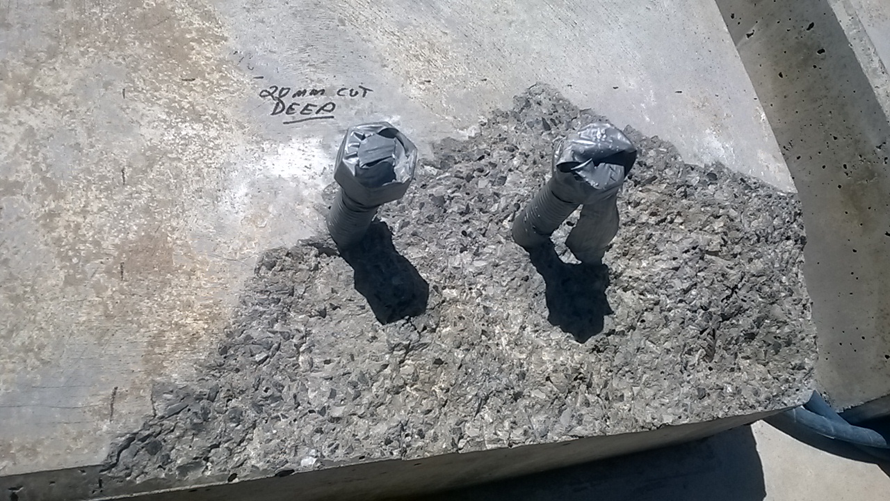
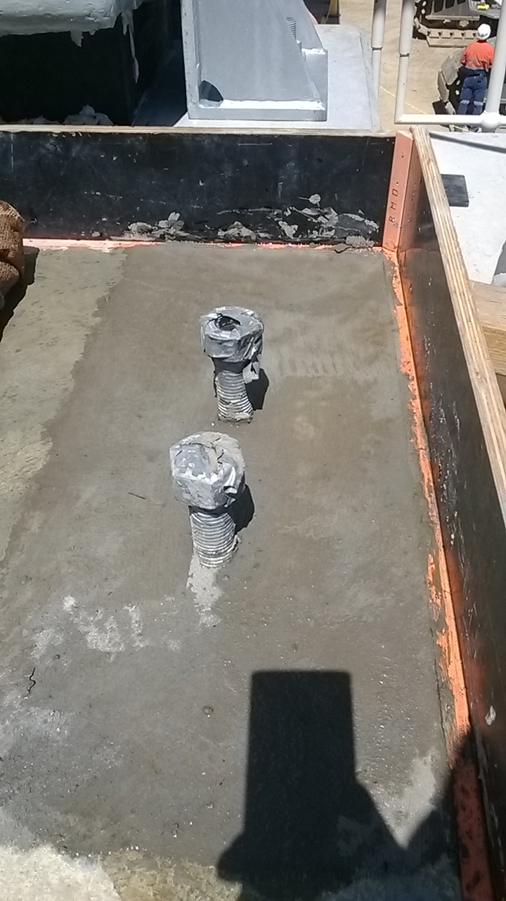
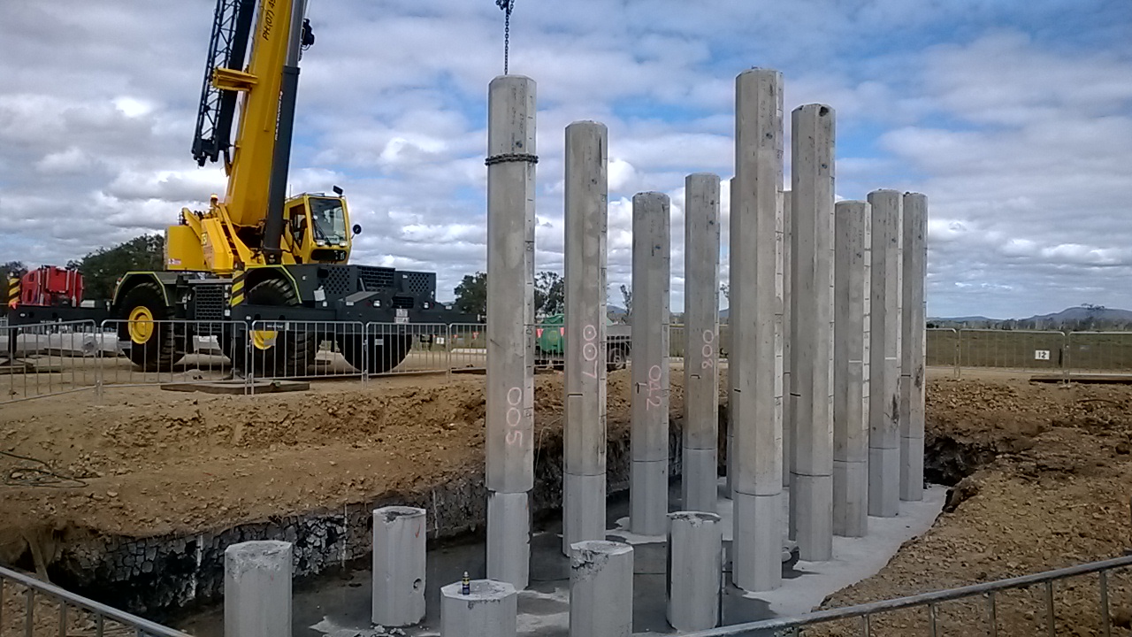
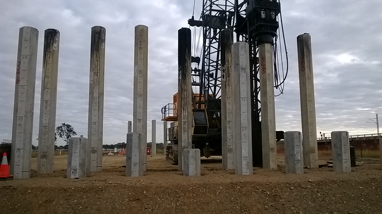
At the start of the project the length of pile that was needing to be cut off was manageable at around the 4m mark. However as progress moved to the middle of the bridge the ground improved and we struggled to reach the underdrive allowance in some piers. This was leaving up to 8m of pile needing to be cut, before breaking down the final metre of pile where the reinforcement is exposed (and then tied into the pilecap).
The process for the shorter lengths had been to cut 7 of the 8 sides with a circular saw to a depth of approx. 100mm. This ensured that the strand and reinforcement was cut. A crane would then hook up to the pile and (for some) snap the pile off. For most piles this would not be enough, and the final side would then be cut, or a breaker on a backhoe would tap the pile and it would swing off. With the increase in length the crew cutting the piles became increasingly worried about the stability of the piles prior to the crane hooking onto them. As the pile breakdown was not on the critical path, it happened whenever the crane was not on more critical tasks. – meaning the piles could be cut and sit for a day or two before being snapped off.
The question then came, has anyone checked whether this method is safe? No, the original supervisor was doing what he’d done on other jobs back in the day. He had then handed over to another supervisor and then the length to cut off increased.
The analysis
Safety and the powers would not accept anything that was not signed off by an REPQ (the equivalent of CEng in Queensland). However I still did my own rough check with a free body diagram of the issue to see if I thought it was safe. I took the worst case possible rake on the pile (but still within tolerance – 20mm in 1m) and I assumed a wind loading of 10% of the self weight of the pile. I decided to include the resistance of the reinforcement, even though it was in compression (mainly due to it being confined by the concrete to stop it buckling. Then I negated the concrete in tension and only counted the concrete in compression. Based on my rough calcs I was happy with the situation. The only thing I didn’t consider was accidental loading (in the form of an EWP striking the piles). The piles are made with 50MPa concrete and have 12 x 24mm dia headbars. I did not include the prestressing strand. The diagram below shows my starting point.
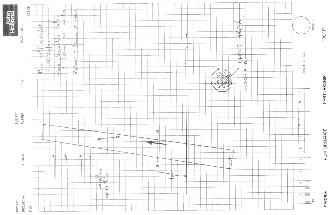
I wanted to see if anyone would approach this a different way to me. I will put my process up after this in a subsequent post (as I don’t want to influence the ideas of others). To give a brief hint there were 2 limits set, one at 4m and the other at 8m with different controls at those points. How would everyone else approach this?
In other news we’ve also started to have a bunch of snakes appearing on site. There were 4 red bellied black snakes on Friday that the catchers had to relocate. Apparently they’re the third deadliest in Australia, might need to put that in my AMS…
Things are getting contractual
Background
The piling subcontractor has been achieving a very impressive level of productivity now that the hammers are finally fixed. In the initial planning stages of the project it was estimated that they would complete 4 normal piles per day, per rig or 3 spliced piles. Recently we have been seeing the rigs regularly reach 7 or 8 piles in one day. The piles that are being used on site are produced in a local factory. This factory has limited capacity, however started weeks in advance of the piling rigs arriving on site. The precast piles that can be produced per day in the factory is limited to 5 of the longer single length piles or 10 of the sliced piles. The plan had been that with the factory starting ahead of the piling rigs they would have enough stock to keep the site supplied and there would be no shortage of supply. The graph below shows the state of pile supply currently. The piles must cure for 7 days before a hold point can be released and they can be used on site. We are now at the stage that there are 7 day old piles arriving on site.
The contract states that John Holland are required to supply 4 standard pile a day per rig, however this would mean that the crews are stood around waiting for most of the day incurring extra costs to the piling sub contractor. To reduce the costs, an informal agreement was made to stand down one of the rigs and go with just one on site. This would allow 3 cranes to be off hired by the piling subbie and dramatically reduce his costs. The crew from the second rig could then move to another job. The one crew that remains would then work much more efficiently.
Issue.
Last week I was called and asked for an instruction to demobilise the second rig. I was going to do no such thing. It ended up being a bit of a stand-off between the Senior project engineer and the piling subbie, with costs of around $16000 per day starting to mount at the end of the week. In the office we were rechecking everything we had signed and all the documents that we had to prove we had met our side of the contract, while collecting the evidence of where Caporn had failed to meet their end.
The outcome
Thankfully there was a dispute resolution process in the contract, with named senior executives from both companies (the regional manager from John Holland and the company director from Caporn) to undertake negotiations. If this hadn’t resolved the issue then it would have progressed to expert determination and finally arbitration or litigation. But it seems that all is well for now. Rig 1 never stopped working and a resolution has been reached that seems to be keeping everyone happy. We have agreed to supply 36 piles per week to the pilers and they have demobilised one rig and the associated cranes. The whole issue is making me look even more closely on the daily reports that I sign and check on the site diary kept by myself and the undergrad that is looking after the piling.
With a variation from the client this has also provided the opportunity to get some piles from another source. As such the piles for the extra spans that have been added will arrive earlier than if the winner of the original pile supply contract had won the variation. They still submitted a price, but it was much higher than previously, which made it a no brainer to go to a different factory.
Other stuff
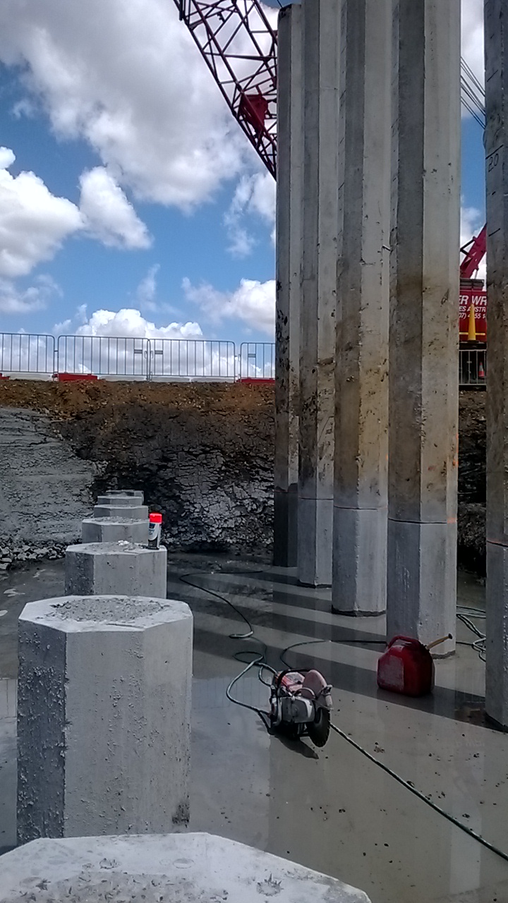
Pier 12 column
Pier 12 column2
The speed that we are cycling through our forms has picked up now, which is good as this is on the critical path and we are now meeting our own targets. The downside has been a drop in quality with some of the elements being produced. In particular the columns seem to be problematic when it comes to consistency of the finish. The worst one so far was on pier 12 (shown above) where you can see the reinforcement exposed and the yellow thermocouple cables (luckily the columns have the least number of monitoring points). I’ve still to write the procedure for how we are going to fix this, and the sections at the top of columns where (after pouring too much) the excess had to be jackhammered out and some of the workers got a bit too enthusiastic. With the root cause being the over pour on the columns there is a lot of effort being put into monitoring that area.
Pier 3 headstock
There were a few temp works issues that have come up too. The method for cutting and breaking down the piles has had to be checked and some extra controls put in place. This was brought on due to the piles only just reaching into the underdrive, meaning up to 7.5m needing to be cut off. I’ll maybe include that in a follow on post early next week. I’ve signed of reinforcement schedules to the end of bridge 1 and I’m starting to plan ahead to the abutments and pier 1 and 2 (though it turns out there is no money in the budget for sheet piling…might be speaking to John about possible alternatives very soon)
Pier 17 piles
I also dragged myself round the Brisbane marathon last week and managed a half decent time considering I had done no training. Tim also stopped by mid week while travelling down the coast and we went to grab a steak. By chance we caught some amateur bull riding in the ring at the back of the pub – just your average Wednesday night in Rockhampton.
The pace quickens
The last two weeks since returning from Tasmania have been rather hectic. It was nice of my site engineers to leave everything untouched so that it took the first week just to catch back up.
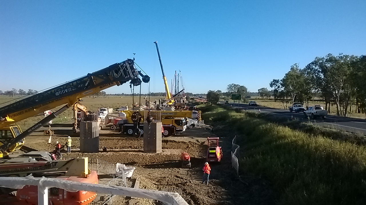
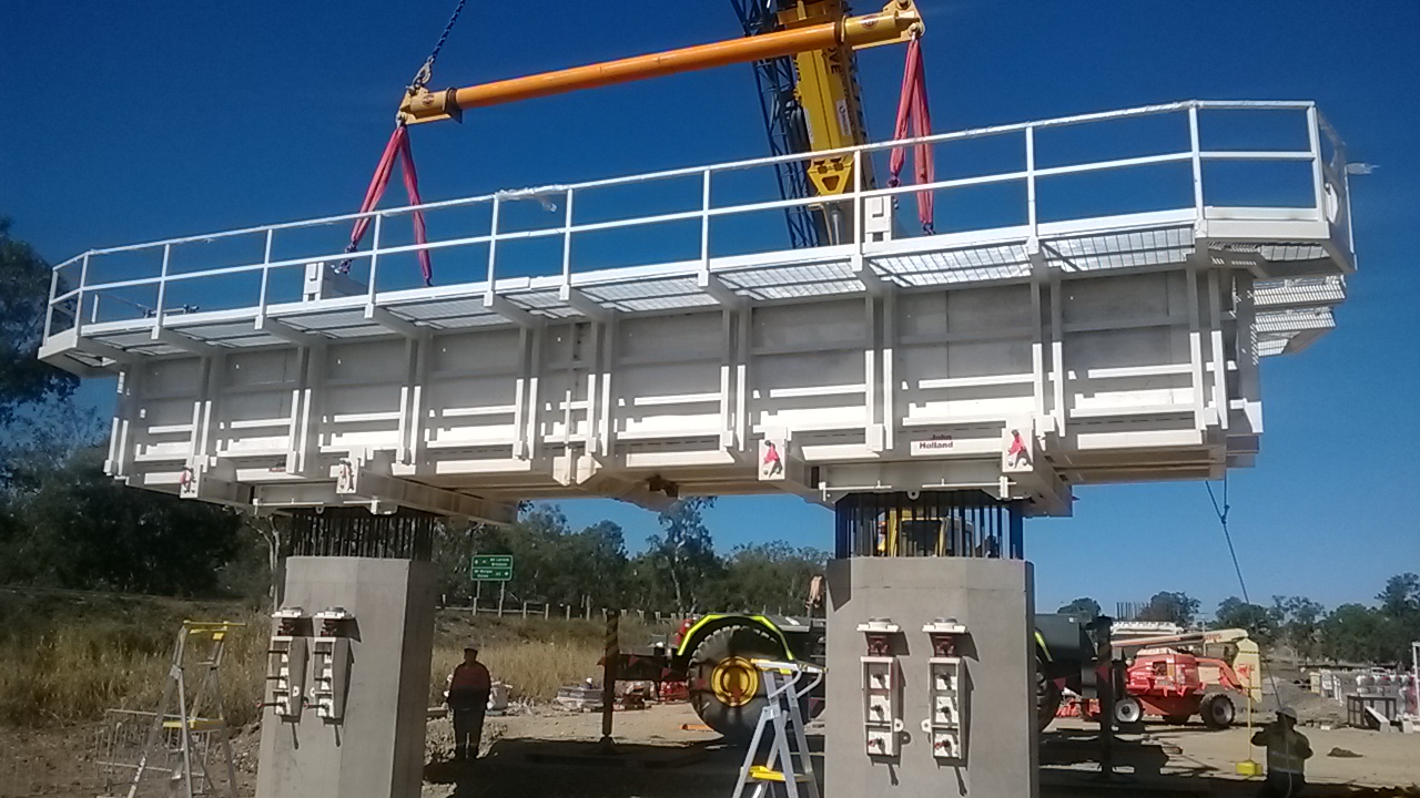
The Form, Reo, Pour process is now in full swing for the pilecap and column section of the substructure. There have been a few teething issues with the formwork, particularly where the pilecaps interact with the columns. This is now resolved and we’re pouring about 2 pilecaps and 2 sets of columns every week, with 2 headstocks soon to be added to that weekly tally. The 280t crane has also arrived on site and been commissioned, ready to lift the girders…if we ever get any.
The changes to the reinforcement in the headstock were finally approved after a meeting with the us (main contractor) the steelfixers (our subby), the clients rep (on site inspectors) and the designers (AECOM). We came to a workable option that satisfied our need for prefabrication and the designers need for torsional reinforcement. Though I still can’t understand their concern when we only needed to change a small section of bars. I did quiz them but got nothing back. I’ve also seen the cage successfully lowered into the bathtub (formwork) and the pour is planned for tomorrow.
There have been issues up at the precast yard recently that I will probably cover in another blog, as the safety investigations are on going. As a bit of background john Holland have built their own precast yard for this project to make the 700 or so girders for the 2 bridges. These are 35m long prestressed pretentioned girders with a lot of strands in them (I’ll get more info in the following blog). The first incident was a prefabricated section of reinforcement for the girders toppling over. While no one was injured, due to the size of the cage and potential to harm this is being classed as a 1P incident (notifiable to the Aussie equivalent of the HSE). The second was during a girder pour 4 strand couplers failed while in tension. With 200KN on each strand this was really dangerous. I will get some of the photos of them smashing through some wooden boards and into the stressing trench wall. Again no one was injured as the controls were in place to stop this. I’ll get more details when I can. Without wanting to second guess the investigation the control appear to have been in place, and as they have let us continue work they must be pretty happy with the process and controls.
The piling crew has now kicked things up a gear and one rig managed to install 8 piles on its own yesterday, when they are only planned for installing 4. This might have a major impact on the supply of piles to keep the rigs busy. At this rate they will catch the casting program in 4 weeks time. To mitigate this the plan is to split the rigs and send one over to start bridge 2 early. All the piles on bridge 2 are spliced and this will slow the rig down considerably. It will also buy more time for me to prepare everything for the cofferdams that are needed for pier 1 and 2 in scrubby creek.
There have been a number of minor dramas and modifications to the headstock formwork to get it to the stage shown in the photos. The first drama was the project manager not approving the purchase order for the stressing jacks in time to get them on site! I’ve now had to go to VSL at short notice and get them here to fill the gap till I could get some kit here (as it happens I got a bargain on some kit from another JHG job that is coming to a close). Trying to rush through a short term subcontract has been a nightmare, mainly due to the terms and conditions that VSL work under. They only want to be liable for 5% of the contract value, but as the contract may only be a few thousand dollars this just isn’t acceptable – if their stressing fails the damage could be in the tens or hundreds of thousands of dollars. However, I’ve managed to get someone onto site though a bit of a loophole (but with the commercial managers blessing).

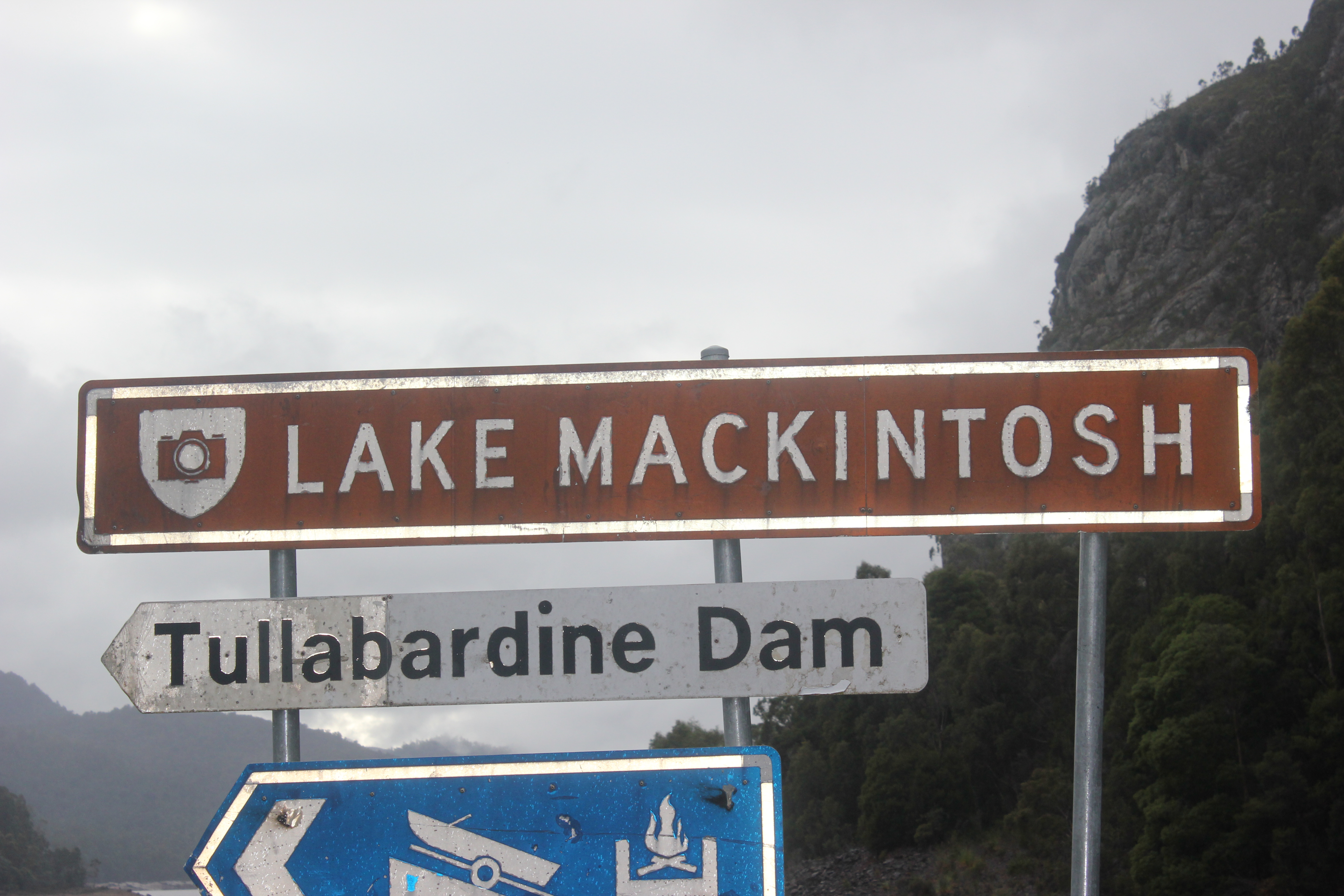
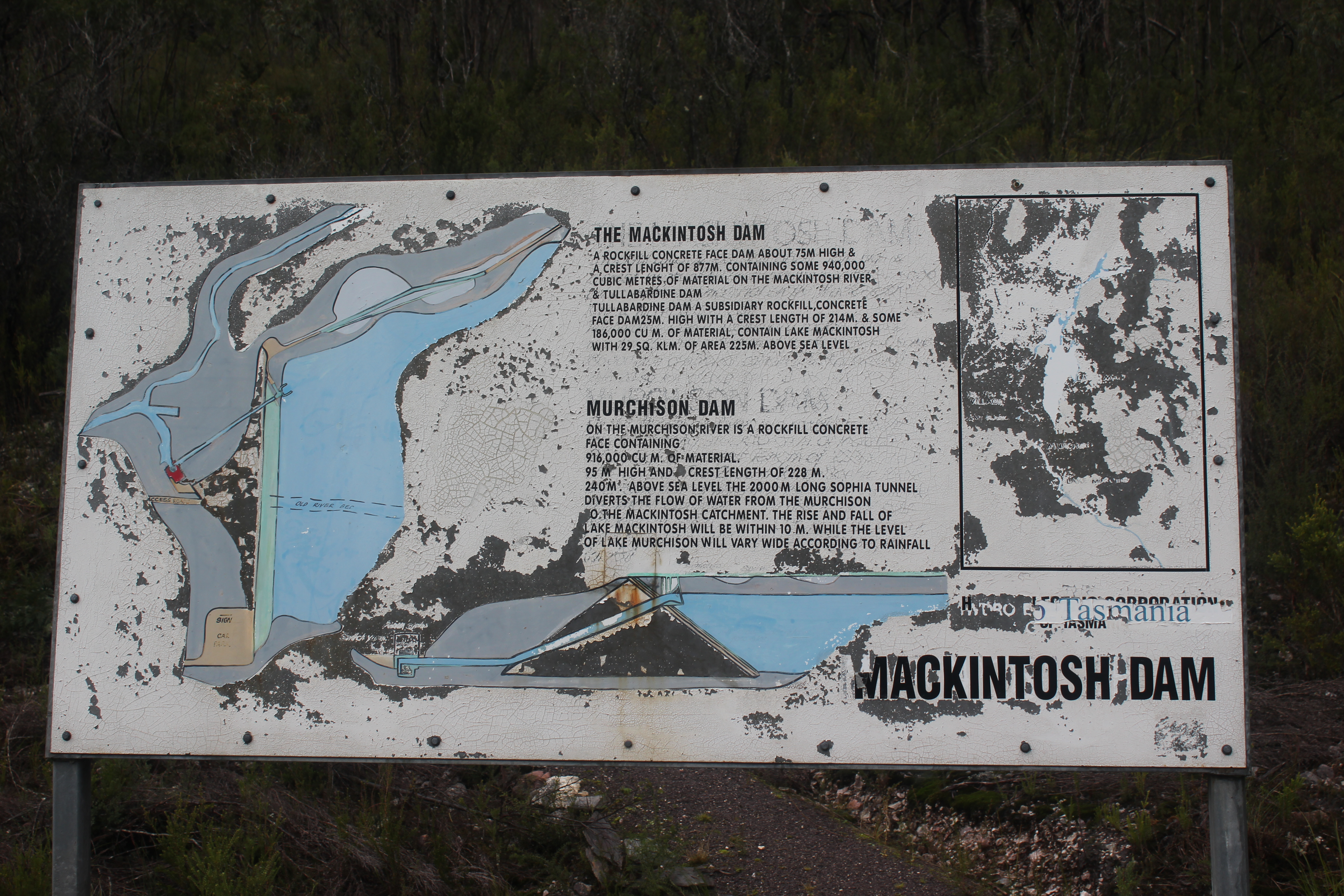
In other news I would thoroughly recommend Tasmania for a holiday – it was great, and they have even named a lake after me. Went and did the Gold Coast Half marathon with Ben and Sharna (though Ben managed to pick up an ITB injury that meant he had to withdraw, so he consoled himself with a few drinks).
Mr Cropper is too blunt
Things are picking up on site. The excavation has now been completed on the first to piers and the piles are being broken down. The hydraulic cropper arrived on site (after much delay it ended up being shipped in from the UK), and it has promptly fell on its arse. It works fine, too good really as it is mangling the reinforcement and strand within the piles that need to be tied into the pilecap reinforcement. There just seems to be too much congestion in the pile for it to work as intended. The helical cage combined with the strand and the normal 24mm bars seems too much for it. The photos below show what the pile cropper in action and what its first and fourth attempts produced. There was an improvement in the technique, but it was still causing too much damage from a QA point of view.
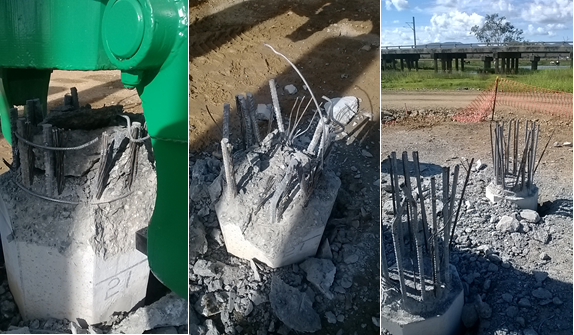
Below is the pile that was broken out through a combination of a rock breaker on the backactor of a LWT and men with jackhammers. I know Joe had great success with the cropper but it seems that the combination of high grade concrete (should be 50MPa but in 28 day crush tests its reaching over 70MPa) with lots of reinforcement is too much for it.
The excavation has been stepped back at a 1:1 bench with a further stand off equal to the depth of the excavation (to make a 1:2 slope). The same geotechnical consultant that is certifying our crane and piling pads has looked at this and he seems more than happy with this for normal traffic. We’ve looked a lot more closely at the loading for the 80T rough terrain cranes that will be lifting the forms into position. Things still seem good when considering the bearing pressures. The biggest problem seems to be passage of information to the guys doing the work on the ground. When barricading was put in to maintain this stand off all was good. I then found out it was moved to get an EWP in closer to the edge for access to something. It seems the workers thought the barricade was to prevent falls into the excavation, and the supervisor hadn’t passed on it was for standoff. Its now been covered in the daily prestart and I’ve spoken with the crew on the ground too. I’ve spoken with the geotechnical consultant about the benching and how long it will be safe for, I’m anticipating a few questions from John on this….
In other news there are still dramas over steel reinforcement in the headstocks. The cages for the columns have started to get tied by the steelfixers. The formwork for the headstocks still requires modifications and I’ve been in touch with the designers Bonacci about modifying their drawings. One of the big questions is how to remove the support frame around the column once the headstock has been poured. This might have to be another blog on its own.
I’m now going to elaborate on what happened on Tims site for the civils that maybe don’t read the E&M blogs. All this information is from either Tim or the John Holland internal safety alert system (JHET). Its been raised on my site and across John Holland as a whole, its of particular relevance as I have temporary excavations currently in place and the upcoming formwork installation too. It seems to be a good way of passing the information and making sure that the group as a whole learns from mistakes – I’m not sure what the others in Oz think about this? Is there an equivalent system on Crossrail?
Description of incident:
A Subcontractor concrete work crew were pouring concrete in Zone 2, Basement 2, Pour 1. During this work, the Bondeck and supporting formwork/falsework, partially collapsed resulting in approximately 8 m3 of concrete in a 40m2 area to fall through deck to lower level. The concrete work crew identified the failing deck and evacuated the area prior to collapse. No personnel were below the deck at the time and there were no injuries as a result of the incident. The site was immediately evacuated.
Contributing Factors
• 32mm of rain overnight prior to the incident affected the stability / integrity of the base plates and tombs on the batter between B2 and B3.
• The Formwork Engineer issued Formwork certificate 5 days prior to the pour, providing opportunity for external factors to change or affect the integrity of the formwork structure.
• Temporary works procedure not implemented adequately
Lessons learned
• Where formwork is supported on two types of ground bearing (e.g. natural earth batter and slab on ground), specific design documentation, inspection regimes and certification processes need to be implemented.
• When Engineer certification is provided for temporary works well in advance of activity and bearing on non-unified material, due to unforeseen delays with potential for alteration, modification or damage to the temporary works, a re-inspection / certification process needs to be implemented
I’ve got piles…in the ground
I’ve spent a lot of my time checking and re-checking steel reinforcement schedules the past 2 weeks. I have very little confidence in the scheduler appointed by the steel makers (Onesteel), and I have picked up numerous mistakes. Some of them may be innocent, but others are obviously in hope to sneak in extra steel as they are paid by weight. Our client will only pay us based on minimum lap lengths, and have issued what they expect the schedule to be, however I have found mistakes in their schedule too (wrong diameters of bars that do not match the drawings issued to us). This made me dig deeper and it seems they are also not following the bar bending sizes in their own standards. There is also some incredibly difficult reinforcement to make work in the headstock. This has been put off for some time due to firefighting other more pressing issues, now it is crunch time. Everything is complicated due to it needing to sit in a glorified bathtub 6m up in the air (just a really big 20 tonne, 12.5m formwork bathtub). SO I’ve been trying to draw lig sets that sit inside other closed ligs (The magic trick with 2 steel rigs that click together springs to mind).
Piling progress has been painfully slow. The brand new hammers that came from Singapore have not been dropping consistently. We thought that one was fixed on the second rig (the manitowok), but then it started to blow hoses. So 3 days were lost due to replacing all the cheap Chinese hoses with high pressure ones made in Australia. Thankfully, it now seems to be working OK, so its moved to pier 3 and started on the Southern end. This is where the critical path is, and where the bridge needs to start getting built from. The casting yard is to the South of the main site and the sequence for girder casting has always started at pier 3. The work done on the North of the site was just to keep the piling rigs busy till the access track was completed. In effect buying us time.
Rig 1 (the Waltman) is still suffering from inconsistent blows every 50 to 100 strikes. After 3 experts have been flown over from Singapore, all with a boxful of parts it seems to be getting better. As I type it is moving from the North to the South of the site to start working there on Monday. By my count the pilers are now 2 and a half weeks behind schedule. I’ve lost time how many iterations of my program I’ve gone through now, constantly changing the plan to meet what can be delivered by the pilers.

The 2 test piles that need to be tested with PDA were finished by rig 2 yesterday. The first one came up well with about 4000KN once it hit the weathered rock layer we were aiming for, however the second one hasn’t (Its at the opposite end of the pier). It could be that the rock layer is deeper here). I called a stop to the driving at the limit of the overdrive allowance as if we drove any deeper there would need to be a lot of remedial work done in fixing up pile to ensure sufficient splice length in the pilecap. While there are ways to deal with such an event it has not been covered or costed in the contract. As such if the client want us to go further than their design we will need to be instructed to and will cost the works accordingly. I’ve also learnt how to use the PDM machine, in the event of someone being off sick or on holiday. It’s a fairly simple bit of kit – I just need to get better at the calculation done following the data gained. And learn CAPWAP for my TMR…

Running parallel to this I’ve been finishing the beast that is the substructure methodology and AMS. This needs to cover all the risks involved with everything from breaking down the piles, excavating, formwork installation (for pilecaps, columns and headstocks), concrete pumping and then stripping the forms. This will take up a lot of my time in the coming week as we near the first pilecap excavation. Oh and the pile cropper should arrive this week, I’m sceptical as to how much time it will save us, but I will let you know in the next blog…
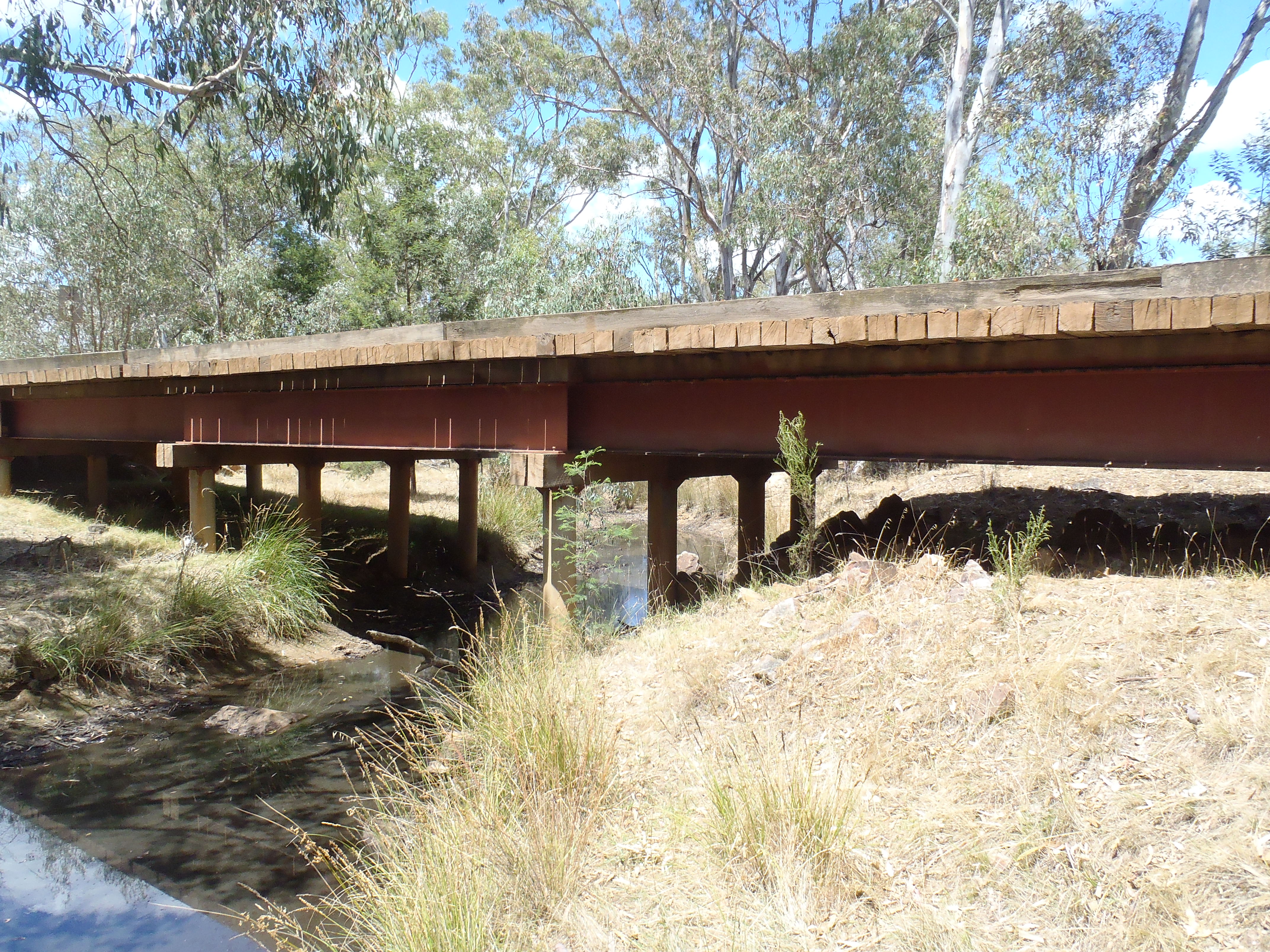
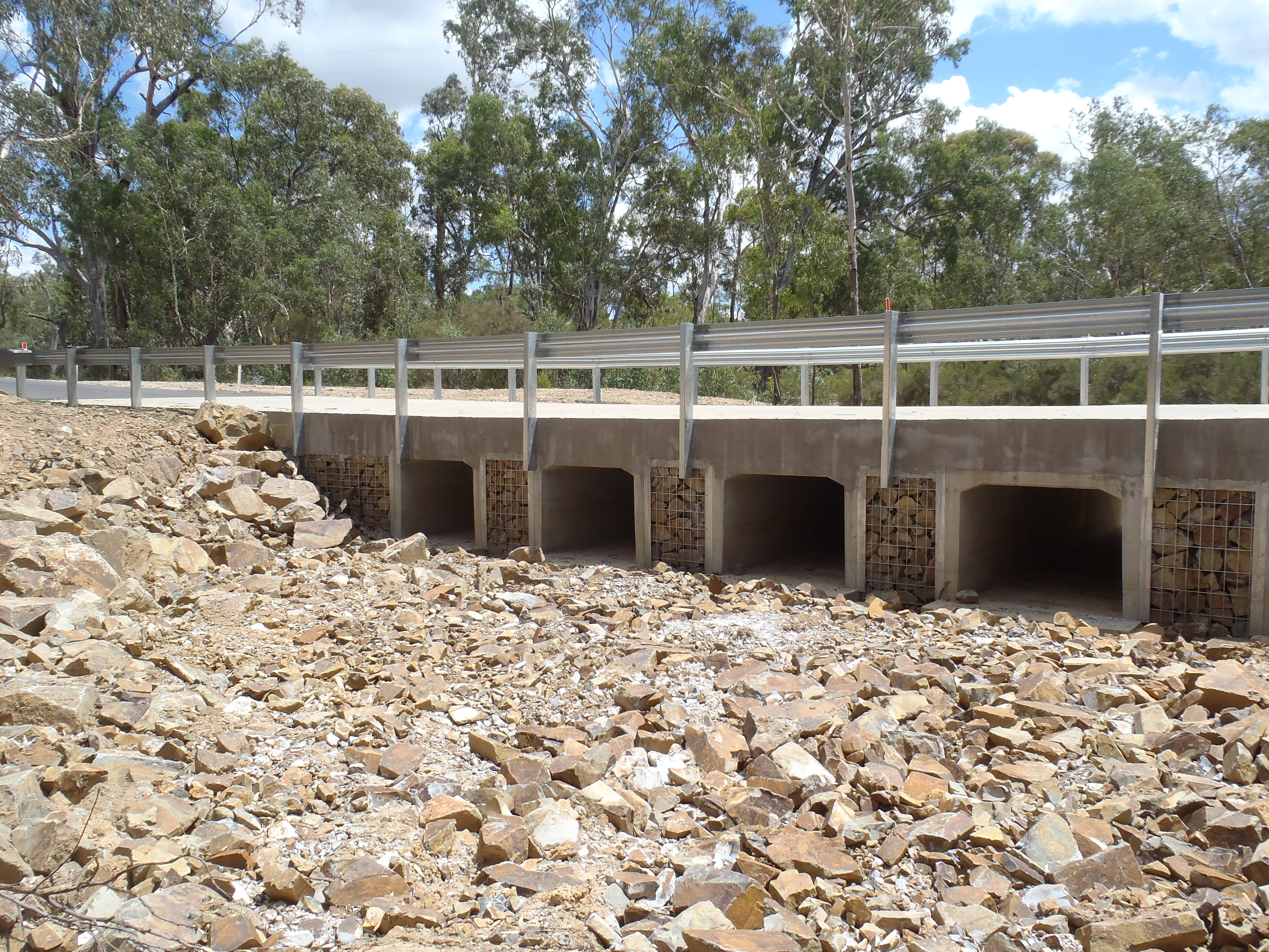
Oh, and the crossing across Scrubby Creek is finally finished.

