Archive
Reinforced Timber in Construction
Having written a TMR on Low Carbon Concrete and the difficulties of specifying it on site, I was invited to attend a MECLA (Materials and Embodied Carbon Leaders’ Alliance) event at the University of New South Wales (UNSW). MECLA are an Australian Government think-tank, combining industry, academic and government professionals, and as part of the conference were reviewing the latest research at the University. Part of this, that I thought would be interesting to the wider course, was research into reinforced timber using prefabricated composite elements by Prof Hamid Valipour. The intent is that these can be used as structural members in mid-rise structures (4-5 storeys).
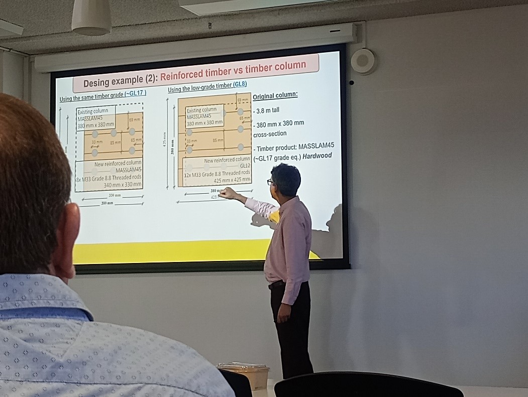
One benefit of the research was that a timber member could be replaced with the same quality timber containing steel reinforcing, leading to a significant reduction in required cross-section to resist load. However, the main sustainability benefit was that high quality timber could be replaced with low-grade timber, such as Douglas Fir. When reinforced with steel rebar, this low-grade timber would still have a smaller cross-section than significantly higher quality timber used on its own and allow lower quality, faster growing timber to be used for structural purposes.
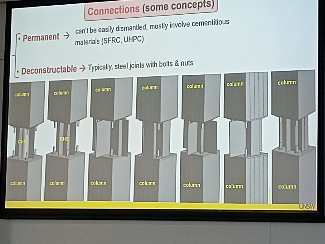
Connections could be de-constructable, created using steel plates (as shown above). These are bolted onto the end of the threaded rebar (the same bars as used in concrete) that protruded from the timber members, allowing the joints and structure to be dismantled at the end of its life. Alternatively, for more permanent structures ultra-high strength concrete, that cured within 48hrs to over 100MPa, was used to connect members, allowing the structure to be load bearing and built in a short period of time, as well as protecting joints from fire.
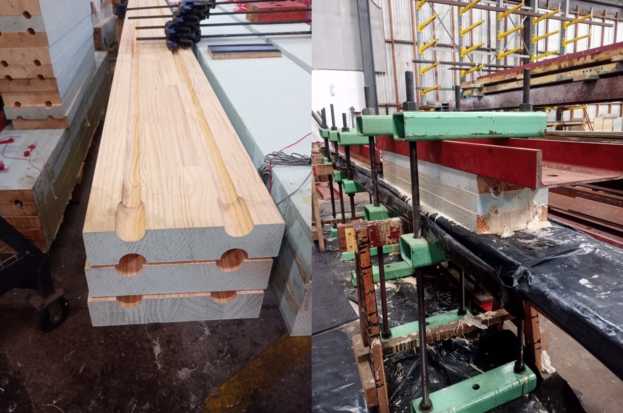
The members themselves are created form beams of glue-laminated timber with grooves cut into them using a router table. The steel reinforcement bar is then placed inside and a glue is poured into the joints to bond the bars and timbers together. These are then clamped and held in compression for 48hrs. Not only are the members very strong, but due to the steel being encased inside the timber, they also have a high resistance to fire.
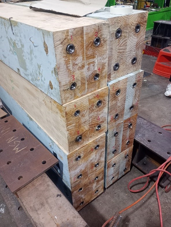
The rebar can either be threaded to be a male or female end as required. They can then be rapidly assembled on site.
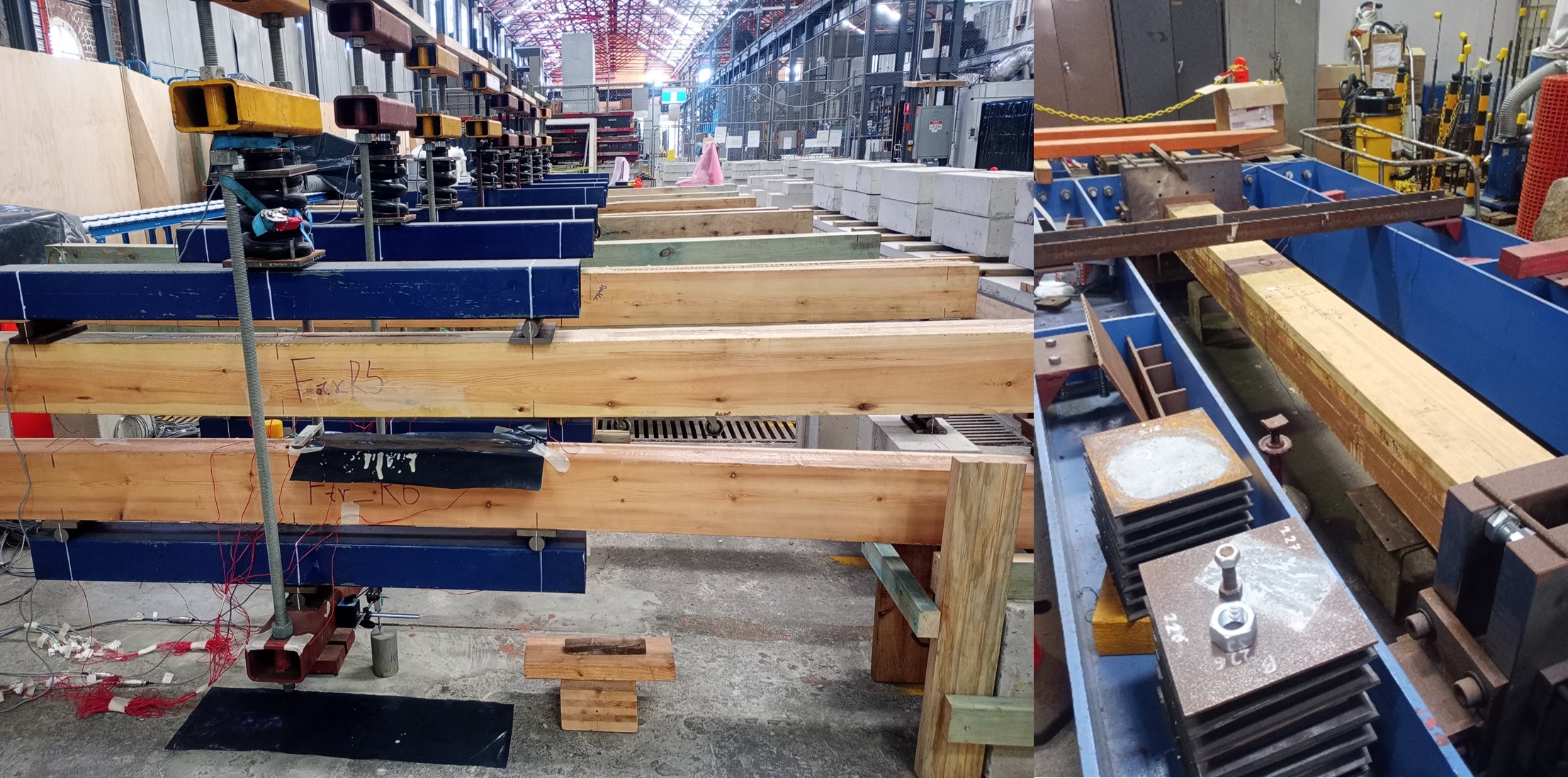
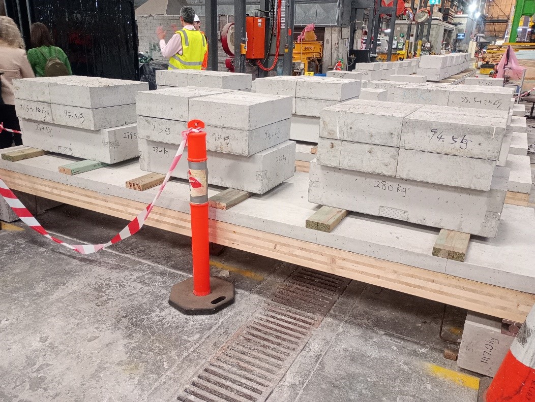
Using this method, beams and columns have been tested with some being left for up to two years to measure creep and verify the quality of the bonds. Beams were also tested for vibration and deflection. It was found that once beam spans were limited to 8.5-9m before vibration and deflection became the constraining factors.
The beams have also been tested as a composite in conjunction with concrete slabs to produce floors. One key consideration when used in this manner was that a membrane needed to be placed between the concrete and timber when the concrete was poured. This was because the concrete would chemically attack the timber, reducing strength by around 1/3.
So far, the project has been a resounding success and Prof Valipour is trying to ensure that all of these members meet existing timber codes to allow a rapid transition into use. However, he did state that it will come down to design consultants to hold the risk of utilising them in design and identifying whether they can meet required design lives (the irony was not lost on me). This further demonstrates the difficulty of utilising new research and techniques in industry but may be something we are able to work with in the near future.
Glued Insulated Joints and Why Not to Use Metal Measuring Tapes
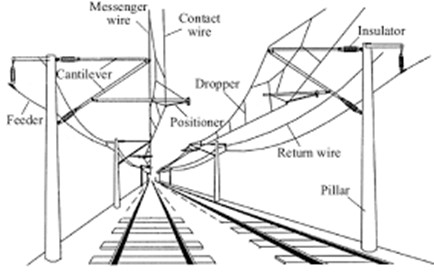
One for the E&Ms but explained in Civil speak! Many Australian trains are electric, particularly in urban areas. These are powered by overhead cables and a pantograph system. Electricity is provided to the train as 1500V, DC power and is converted through a rectifier and inverter to three-phase AC power to power the motors. The circuit is completed through the train wheels touching the steel rails which act as a return conductor to the nearest transformer.
Additionally, there is a second current in the tracks, at a different frequency and very low voltage, that is used for signaling. The wheels and axles of a train entering a track circuit connect and short circuit the two running rails together, causing the current to drop to zero. This provides information to the signal gantries, turning the lights red to tell other drivers that there is a train on the section of track ahead of them. This information is also fed to the control desk to allow the tracking of all trains in the network. The system is designed to make signals turn red everywhere if there is a power outage, but the voltage is so low that water pooling between the rails does not cause it to short.
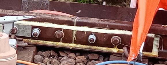
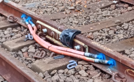
For these track circuits to work, sections of rail need to be broken up with insulated joints to allow more accurate location data to be provided. These are known as Glued Insulated Joints (GIJs), as shown in the picture below) and come prefabricated into a section of rail 3.43m or 4.57m long (or specially made if required). These are tested under factory conditions to ensure they function correctly. To fit them, a section of the existing rail has to be cut out and the new prefabricated section is welded into place. This falls to the civils team.
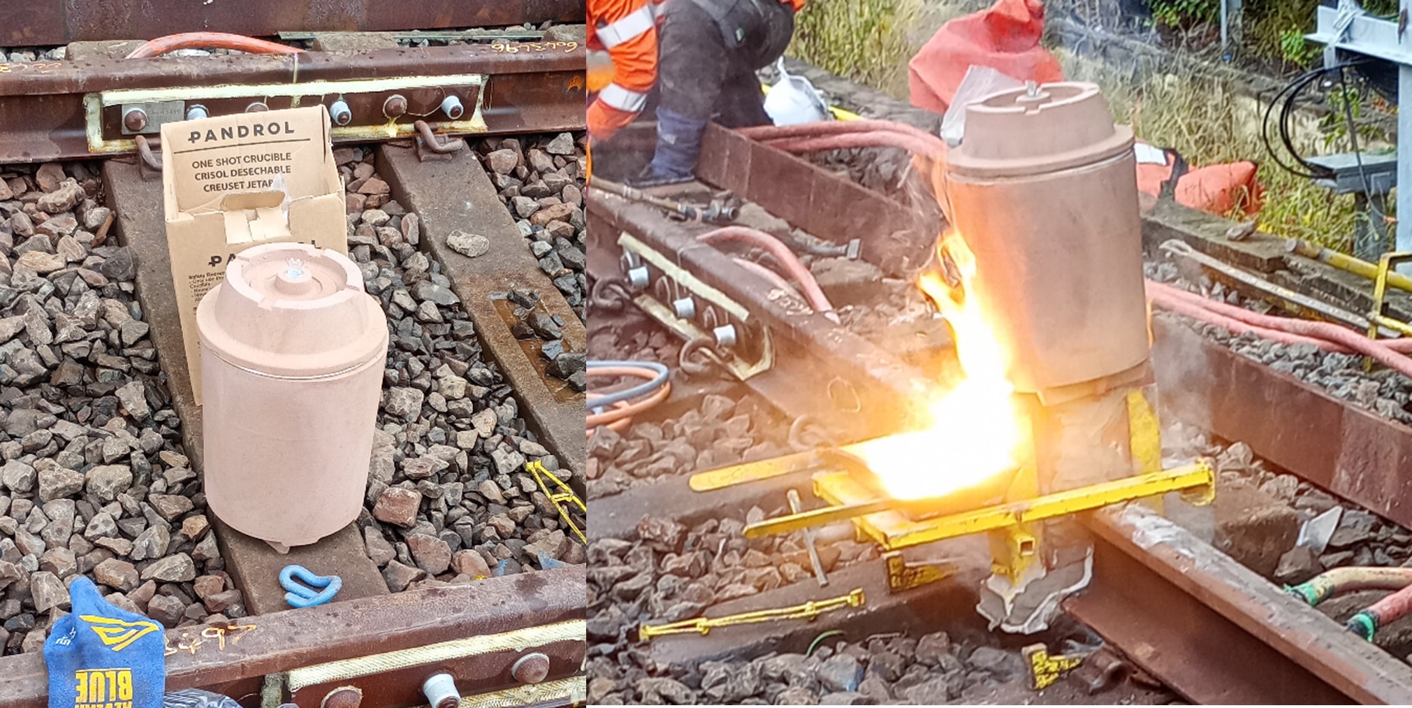
A single use mold is fitted over the gap in the rails and rubbed in place to shape it as closely as possible to their worn shape. It is then sealed with a clay mix and an oxyacetylene torch is used as a preheating flame to warm the rails that will be joined (to 1000 degrees) and to fire the clay.
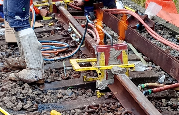
A single use crucible is then placed on top and ignited by sparking between the two prongs of an igniter fuse. The crucible’s filling consists of 37% aluminium, 13% steel, 37 % iron oxide and 13% alloying. This mixture is known as thermit and when ignited a reaction takes place that raises the temperature of the contents to 2500oC within 30 seconds. This reaction creates liquid steel which sinks to the bottom of the mold and liquid slag that rises and overflows into the slag tray.
This is then allowed to partially cool before a hydraulic trimmer is used to shear off excess material and break away the mould.
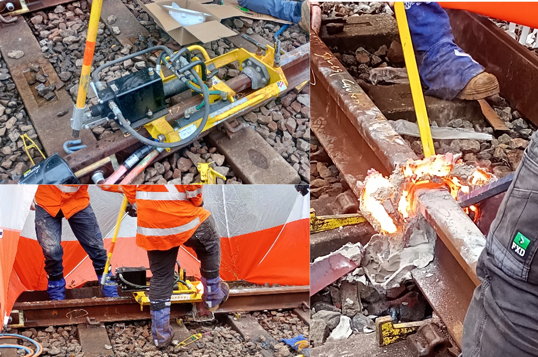
A rough grinding is then carried out using a spinning grinding stone that can be raised and lowered. The joint is then allowed to cool to ambient temperature and shrink completely before a finishing grind is carried out. This prevents a dip forming that would mean the joint has to be cut out and replaced (as the acceptable vertical tolerance across the joint is only 0.3-0.4mm across the two rails). This is checked using a straight edge.
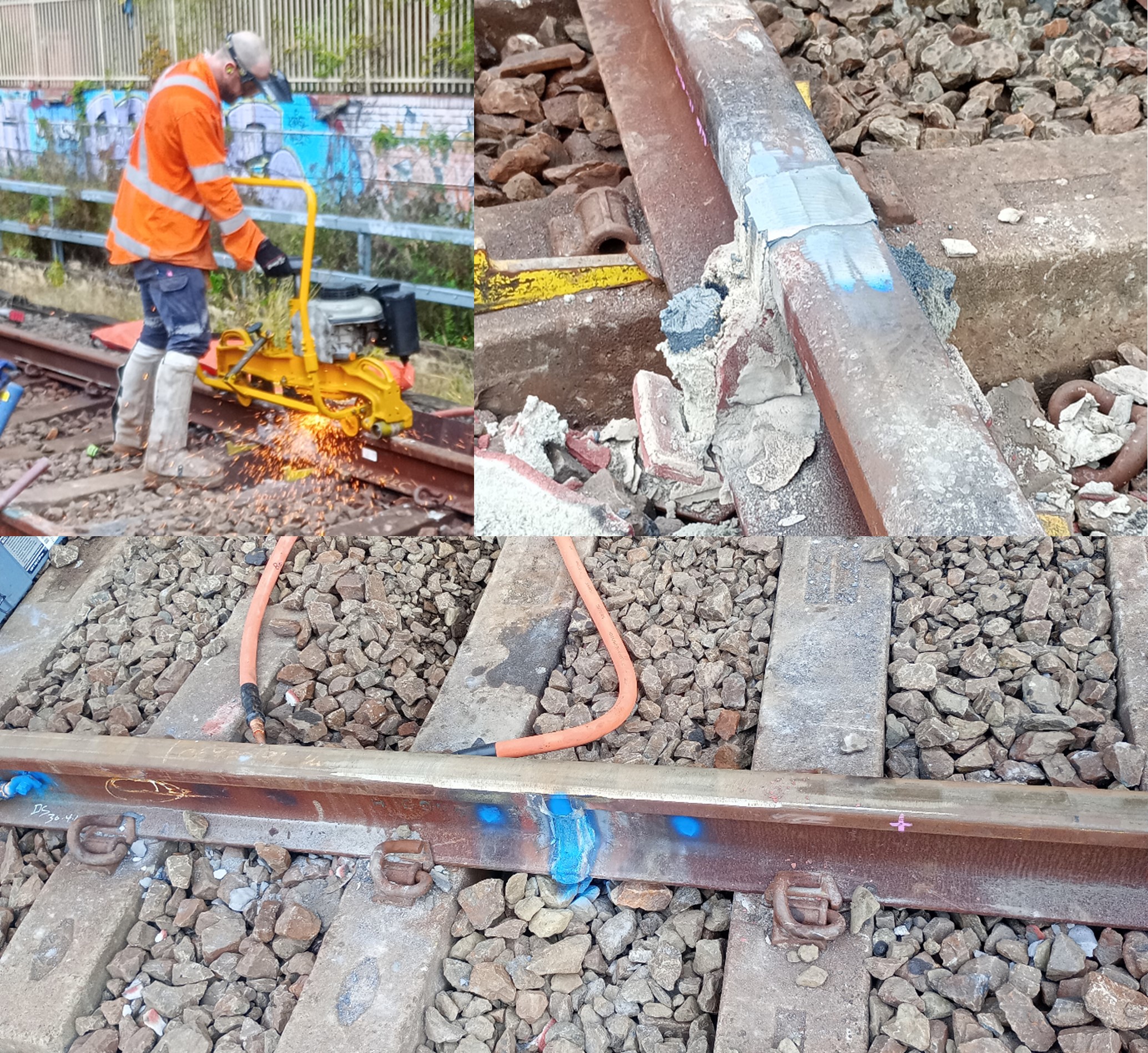
Cables are then welded either side of the GIJ. These are left bonded when it is not in use and will be removed once the signals have been commissioned.
Key takeaway
Rails may be live even if it the power lines are overhead and have been disconnected – no metal measuring tapes in the rail corridor!
More Trains More Services – Next Rail
For my Phase 2 placement, I am working as a Project Engineer for John Holland supporting the development of rail infrastructure in Sydney. This is as part of the More Trains More Services (MTMS) multi-billion-dollar programme and is focused on power upgrades, signalling, stabling facilities and station platform upgrades. This will deliver trains every two and a half minutes in peak hours on key corridors.
Key Project Stakeholders
John Holland Group (the Principal Contractor) is working in partnership with Transport for New South Wales (the Client) and Jacobs Engineering Group (the Principal Designer). The three groups have been combined as “Next Rail” and are described as an Incentivised Delivery Entity (IDE), with the intent of sharing any benefits/losses on completion of the programme. Additionally, Sydney Trains (a department of TfNSW) is the Operator/Maintainer and take a keen interest in works that are done. This partnership has created a complicated hierarchy and has already led to stakeholder engagement and expectation management being a key part of my role.
The Delivery Commissioning and Handover Team.
My initial work has largely consisted of closing snags and overseeing commissioning work. For example:
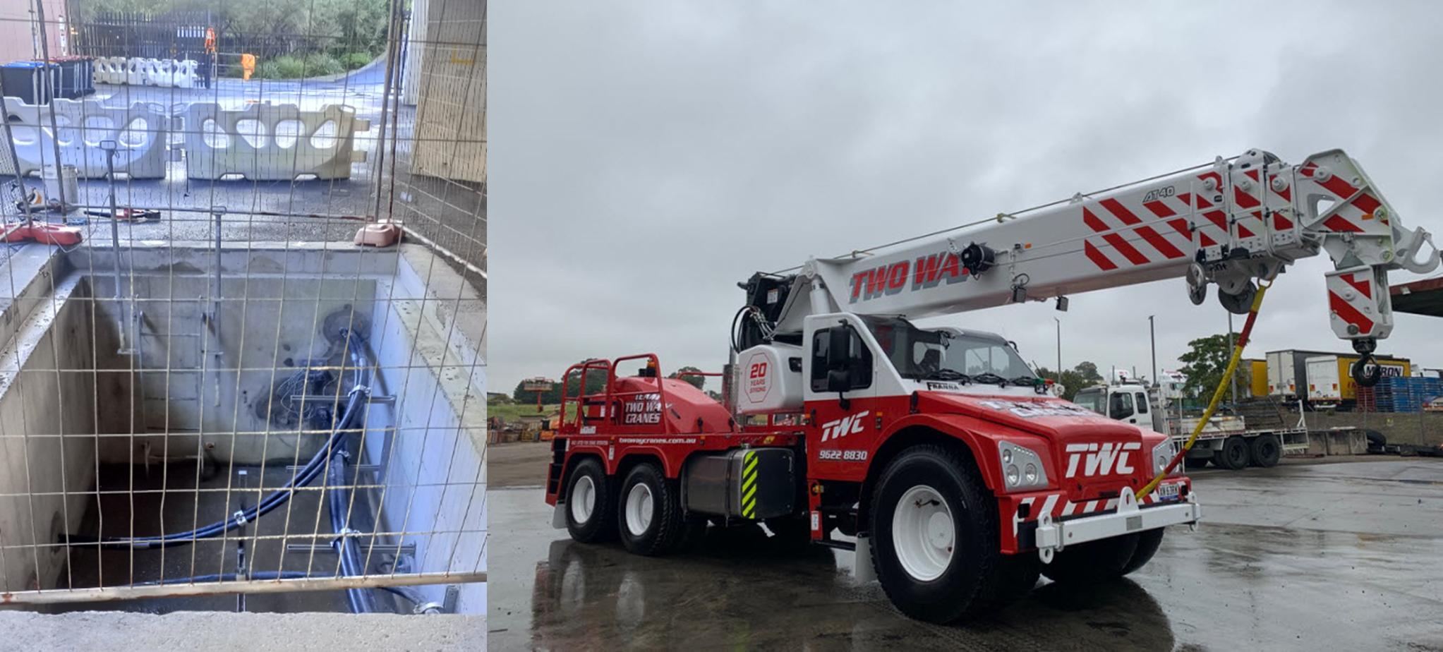
- Overseeing the commissioning of 11kV feeder cables from a new substation (to increase supply) and removing redundant ones. This was done during the early morning when electric trains were not running. It required use of a Franna crane to lift a cable pit cover (after the cables had been isolated) due to the overhead restrictions. This was a piece of equipment I had not seen before and was able to lift the 5.5ton lid with the boom in the lowered position (shown below).
- Replacement of sections of overhead wiring and strengthening overhead gantries to resist torsion. This was heavily delayed due to power leakage between lines – it is often difficult to isolate lines to below the 50V required for work to be allowed to take place. This causes significant delays and immense cost to Next Rail despite being out of their control. Other issues have been the need to vermin proof signalling boxes to prevent chewed cables!

Wolli Creek Demolition Task
The main task I am working towards is the demolition of some redundant assets and their replacement with an access road/long vehicle turning area. This will include importing fill from another site to raise the existing ground level and there is current discussion as to whether this can be ‘contaminated material’. The site is situated at a rail junction, between two rail corridors and an area of residential high-rise flats.
Key risks noted so far have been:
- Contaminated Ground. Rail corridors are often built on landfill and due to oil and waste leaks from locomotives, almost all the sites have been found to have contaminated ground during excavation (even asbestos panels encased in concrete). This has led to significant costs and delays that were not considered in the planning stages.
- Underground Services. As well as 1500V DC overhead cables, the site is surrounded by live underground services and a high-pressure gas main. In Australia, “positive identification” and “positive location” is required, meaning that any excavation is likely to require a suction excavator.
