Archive
Remember these John?
As many of you will know I have opted to stay with the BP Exploration Operating Company Ltd (BP) for Phase 3. I am remaining with the Projects and Modifications (P&M) team and so will continue in a mainly Project Management role. In order to gain design competency I will be taking on work from the Discipline Engineering (DE) team. One of said pieces of work involves this:
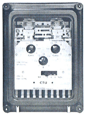
GEC CTU15 Relay
No, not a flux capacitor. This is an obsolete mechanical protective relay from the aging Magnus platform; E&Ms will remember studying these in great detail with John Marsh. The problem is that being obsolete there are no spares available if any fail, which some have started to show signs of doing during routine testing.

BP Magnus
The task for DE is to find a solution which doesn’t involve replacing/modifying 35 year old feeders, air circuit breakers, bus bars and current transformers or 39 electrical cabinets. The Magnus’ high voltage transformers and feeder setup are a bit of a unique design and even replacing the existing current transformers would be at best challenging and at worst dangerous. Unless you shut down the entire platform, which at $1million per day production loss isn’t going to happen.
My job is to engage with a vendor who claims to be able to utilise the existing relays to develop a plug and play digital replacement. This may be using the existing casing or an interface plate to install a contemporary relay in the existing Magnus cabinets. If the solution is viable and passes a FAT, I will need come up with a plan of prioritising the replacement of relays on the platform, the testing procedures and the programme for installation. There will inevitably be quite a number of discrimination curves to draw too. Best I jump on Air BP to Manchester and undertake some vendor engagement…
Materials Audit
Following loosely on from the current E&M theme of FATs and SATs I today visited the BP warehouse to check the materials and fabrications for one of my projects. the warehouse is operated by ASCO and located nearby in Dyce. The purpose was to check that the materials delivered matched the requirements of both the BoM and design drawings. The warehouse is pretty much brand new and accommodates both spares for existing platforms and the materials for repairs and modifications. Warehouse pictured below:


Materials are held here and ‘called off’ when required, which involves packing the materials into shipping containers and delivering them by road to Aberdeen harbour where they are transferred by ship to the offshore platforms. Upon auditing the materials for the project in question we found everything to be present and it looked in good order:


Whether the materials reach the platform in the same condition and complete is another matter. Compared to the plant in Stu’s post, the internals are protected from ingress and corrosion with blanking plates. We did however had a look around the warehouse and there were materials (not related to my projects) in a similar condition to what Stu found:

It seems to be down to specification. The blanking plates and protected ends of the pipes and valves are specified by BP and the slightly orange pipework above is likely to be blasted and painted as per BP spec if it ever used offshore. As to the effect on flow of internal corrosion I’m not sure. Maybe a topic for a TMR…
Also of note were the PPE requirements. We required safety boots, goggles, hi-viz and hard hat as a minimum to enter the warehouse. A bit different to the farmyard Stu visited by the looks of it. Even Gary’s hi-tech factory visit seemed to allow a ‘come as you are’ policy. Probably one of the many offshore safety aspects that permeate through to the onshore parts of the business.
The total value of the materials checked was £38,000. Not bad considering they are all custom fabrications to the project specifications and designed to withstand both the offshore environment and the corrosive hydrocarbons they will contain. The value is also a pittance compared to the $2.5 million per week of product which will flow through them.
RAT or Scaffold?
This time we’re on the BP Clair asset, West of Shetland, and the issue is access. Part of the scope of one of my projects is to install an additional 3/4″ drain line in the potable water storage system, in order to eliminate dead legs in which nasties such as legionella can lurk. Whoever designed the platform decided to put one of the drain valves 18m above the deck along one of the drainage pipe runs. The valve is circled in the below image (you’re looking straight up from the lowest deck level and the next deck up is the grating above and right of the valve).
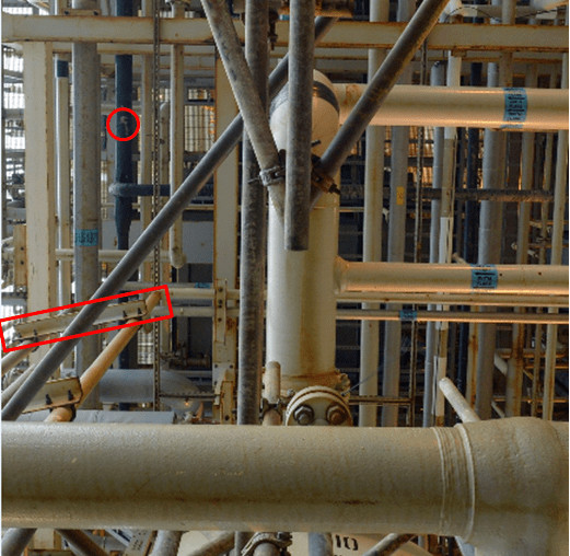
Clair Drainage Valve Location
The new drain line will run down the support structure identified by the red oblong, with a valve at deck level so that the system drains from the deck through the grating into the sea. It’s potable water so we are ok to do that.
Getting to the valve is the problem. We can’t use a mobile access platform as such things just aren’t feasible offshore. So the answer is either a rope access team ‘RAT’ who, as the name suggests, hang off the structure on ropes to carry out the work, or build a lot of scaffolding.
The RAT are expensive due to their additional qualifications and training and there are added risks in terms of them dropping stuff and delay due to adverse weather. They are however quick and there is limited impact on platform operations or other projects.
Scaffolding greatly reduces the risk of dropped objects and construction delays but requires additional manpower and is much more time-consuming, doubling the offshore execution time. It is also very heavy and gets in the way; A few weeks ago the Clair platform stopped all non-operational work until all unnecessary scaffolding was dismantled and removed.
So what’s the answer? “Well it’s a balance between time and cost, what’s the client’s driving factor for the project?” I hear you respond. That’s exactly what I have asked the platform to decide and I’ll report back on the decison. Any views from the floor on a method of choice or similar experiences?
Project or Programme?
You will all have been waiting eagerly to hear how the execution of my caisson swage repair went. I mentioned in my earlier post the issues with a crane outage and competition for deck space in the laydown area. It also transpires that the HVAC in the Bruce utilities room (see image) where the work will take place is not working, thus making the room a confined space. These issues have conspired to push the scheduling of the C16 back into late September.

Bruce Utilities Room
By pushing the timing of the C16 repair back, it aligned with the scheduled repair of the next caisson, C15. With typical military enthusiasm I claimed this second repair as my own project and it became clear there were efficiencies to be made by completing both repairs back to back. Wood Group, BP’s engineering partner have produced a combined construction schedule and the saving of combining the work scopes is in the order of £200k.
At this point I hit yet more issues as the repair is dependent on an inspection being carried out by the Integrity Engineering team. This inspection can’t take place until the core Bruce engineers remove the pump and its riser, the sectional pipe that connects the pump to the distribution pipework (top right in the above photo). It transpires that the riser from C16 is sat in the racking in the utilities room (bottom left of the photo). Guess where the C15 riser needs to be put?
So what we have ended up with is a series of 3 related projects all with elements of their scope which are similar, taking place as a sequence, in the same place. From what was covered on the APMP course that sounds very much like a programme. Treating the 3 projects as a programme and appointing a programme lead should ensure any issues which affect the other projects are identified and mitigate and may lead to further efficiency savings.
As if my first project growing arms and legs and becoming a programme wasn’t enough I have been tasked to conduct a portfolio risk review for all the projects being undertaken by the Projects and Modifications team.

Bruce C16 Caisson Swage Repair
 If the title of this blog makes absolutely no sense to you then you’re at the same starting point that I was when this project was handed to me! This project is currently the top structural integrity concern in the BP North Sea portfolio but is actually relatively simple once you get your head around what’s involved. The project pretty much covers all the core competencies, focussing mainly on contractor management and project management, with a good dose of health and safety due to the nature of the offshore industry and some complex lifts which are required.
Background
A caisson is effectively a big pipe which extends from the deck of an offshore platform down to below sea level. Its purpose is to minimise the effect of waves on seawater lift pumps (seawater being the obvious choice offshore for cooling, processing and fire fighting).
The BP Bruce asset, comprising of separate drilling (D) and process, utility, quarters (PUQ) platforms is located some 200 miles East of Aberdeen and was built in the early 1990s. The PUQ platform has a number of caissons which are shown in the images below and right (circled in the photo and labelled with hexagons on the drawing). The dashed lines in the drawing are the jacket (support legs and bracing) of the platform. The caissons are attached to the second horizontal brace down. Sea level is approximately at the midpoint of the top set of cross bracing.
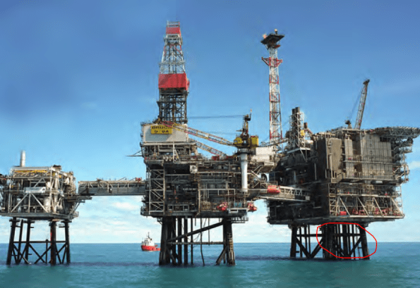
BP Bruce Asset (Seawater Lift Caissons Highlighted) & Jacket
Due to a combination of the age of the asset, climatic conditions and the corrosive nature of seawater, structural integrity is a constant challenge. The point where the caissons on Bruce are attached to the platform is the point of greatest stress and corrosion and caissons C12-C17 have suffered major cracking (example shown below in photo). Why this is such an issue is due to the ‘dropped object’ risk. If the caisson were to break at the crack then 30 m of 1 m diameter steel pipe would plummet towards the seabed. There is a risk if this happens of damaging nearby caissons (and therefore the ability to fight fires), the jacket (therefore putting platform integrity at risk) or equipment on the sea bed (therefore putting production and hydrocarbon containment at risk).

Bruce Caisson Crack
Options
In order to address this risk BP considered 2 options:
Option 1 – Replacement. This is something that Imran was working on several years ago and was cancelled due to cost. Replacement would involve procuring a new caisson and all the related deconstruction, transport and construction works. This represents a significant investment; whatever you think it will cost, add 3 zeros in cost and triple your time estimate for offshore! In the current economic climate costs are being minimised and so this option is unlikely to be funded. Equally the life of the new caisson would far exceed the expected life of the platform and greatly reduce any return on investment.

Swaging Tool and Liner
Option 2 – Swage Repair. This is the option chosen and the one which I will be responsible for executing offshore. First the caisson is internally cleaned using a tool which utilises a high pressure jet of water to remove marine growth and corrosion. An internal liner is then lowered down over the crack before the swaging tool is inserted (see image). The tool is pressurised to expand the liner beyond its elastic limit whilst remaining within the elastic limit of the caisson itself. The liner is thus held permanently in place and seals exactly to the shape of the caisson. The process is illustrated in this handy video.
The Project
The main contractor for the project will be BP’s engineering partner, Wood Group PSN (WG PSN). Two specialist sub-contractors (known as ‘vendors’ due to BP’s global nature) will be involved. Sparrows are an offshore lifting contractor and will be responsible for the lift plans, rigging and executing the lifts (example shown in image below). Oil States, an offshore engineering specialist, own and operate the swaging tool and have fabricated the liner. I recently attended the 6 week constructability review where, as the client, I approved WG PSN actions thus far and the offshore execution schedule. Additionally I have carried out the project risk assessment in line with BP’s risk matrix and HSE guidance. This led me to identify the risks associated with the lifting and I have raised these with Sparrows. As this is the third project in a series of 4, the remainder of the risk assessment related to on-going risks and those identified previously.

Example of Complex Lift Procedure
The C14 caisson on Bruce underwent a similar repair in September 2015 and the procurement for the project included that which was required for C16 and C15 (I will likely take on C15 as a project once the C16 repair is complete). The liner and additional fabrications required are currently in storage and I am assured they will be inspected and re-certified prior to project mobilisation. Mike has blogged previously about some of the issues with materials going missing offshore so this is an area of concern for me. Other than a substandard bill of materials I was handed in the 6 week review I have had no issues so far.
Other concerns relate to the site itself. The laydown area outside the pump room where the swage repair will take place is fairly tight for space (see image below). I am competing for time in the asset schedule with another project which also requires the use of this laydown area. This, combined with the fact that the crane needed to lift my containers onto the laydown area is out of action until 4th July is already causing project delay to creep in. I will shortly be having a meeting with the other project team and the asset engineering team to de-conflict the projects and discuss the crane issue. The meeting may also see the scope of my project expand to include the C15 repair immediately after C16.

Bruce Laydown Area
Finally there is one fairly show stopping problem with this project in that the very expensive, vendor owned swaging tool might just get stuck in the pipe! Luckily Oil States have a procedure for this and the tool has a number of shear pins which can be broken by using an over pull tension in the lifting cable. Unfortunately the overhead gantry crane in the pump room is not rated for this. Fortunately a ‘strong back’ frame was fabricated for the C14 repair, which combined with some big jacks can be used to produce the required tension. Unfortunately the deck plates on the floor of the pump room aren’t robust enough to support the strong back frame. Fortunately some large steel plates were fabricated for the C14 repair which can be placed on the deck to spread the load. Suddenly it can be seen where the extra cost and time comes in for offshore projects!
Summary
So yes, that’s it, after months of the PET course and highly technical study, I have been placed in charge of a project to put a pipe inside another pipe! There is a lot of de-confliction which needs to happen to get the project mobilised but I have taken over at a time where the onshore execute phase is all but complete. Next month I should be offshore during the swaging process and will report back on the offshore execution.
